How RF Isolators Improve Power Amplifier Protection
Updated on:
Keywords: How RF Isolators Improve Power Amplifier Protection, RF isolators, power amplifier protection
In high-power RF transmitters, even a short burst of reflected power can punch above its weight: it elevates device junction temperatures, pushes transistors into unsafe operating regions, and accelerates wear-out. RF isolators act like one-way valves, absorbing reverse energy before it reaches the PA. This article explains why isolators matter, how they work, which parameters determine real protection, and how to select the right device across microstrip, coaxial, and waveguide platforms.
Introduction
Power amplifiers (PAs) sit at the business end of the RF chain—closest to the antenna, most exposed to mismatch, and most expensive to replace. When an antenna is detuned by rain, ice, motion, or frequency shift, the return loss deteriorates and standing waves develop on the feed. The result is reflected power that surges back toward the transmitter. Without a protective device, this reverse energy can force the PA into high VSWR operation, triggering current spikes, gain compression, thermal runaway, or even catastrophic device failure. An RF isolator solves this by enforcing directionality: forward power flows to the load, while reverse power is diverted into an internal resistive load where it is dissipated as heat.
Protection focus: reverse isolation & match stability
Primary risks: high VSWR · thermal stress · oscillation
Typical use: radar · SATCOM · 5G/6G RAN · T&M
The Challenge of PA Protection
In practice, antennas rarely remain at their datasheet match. Arrays scan, radomes wet, feeds age, and multi-band systems move across sub-bands with different impedance boundaries. PA designers must therefore assume a non-ideal return loss—10 dB (≈1.92:1 VSWR) in benign cases, 6 dB (≈3:1 VSWR) or worse in harsh environments. Under mismatch, the transistor sees elevated drain voltage and current, which increases channel temperature and exacerbates electromigration and hot-carrier effects. The system can also oscillate if reverse gain and feedback paths line up, especially in long cable runs or multi-module architectures. Adding a properly specified isolator breaks this loop by reducing reverse power delivered to the PA and stabilizing the impedance the PA “feels” over frequency.
How RF Isolators Work
Isolators are non-reciprocal two-port devices typically realized from ferrite junctions under a DC bias field. In the forward direction, they present a low-loss path; in the reverse direction, they rotate the RF field such that energy is coupled to an internal termination. The result is high isolation (attenuation of reverse power), benign match presented to the PA, and improved system stability. While microstrip and drop-in geometries prioritize compactness and integration, coaxial and waveguide isolators are favored where connectors or high-power handling are required.
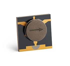
Hzbeat SMT Microstrip Isolator — compact T-junction ferrite design for dense RF front-ends. Image © Hzbeat. Source: hzbeat.com.
Parameters That Actually Protect the PA
1.Insertion Loss (IL)
IL adds directly to the transmitter budget and generates heat inside the module. For PA protection, lower is better: it preserves efficiency and reduces thermal load. Microstrip solutions often achieve low IL in S/C/X bands; at higher millimeter-wave bands, waveguide variants may be preferred for extremely low loss.
2.Isolation
Reverse isolation determines how much reflected power is kept away from the PA. In many systems, ≥18–20 dB isolation is a practical floor; higher values are desirable when long harnesses, duplexers, or couplers create multiple reflection planes.
3.VSWR / Return Loss
The isolator’s own port match should be good (e.g., ≤1.3:1 to ≤1.4:1 VSWR across band) so it doesn’t introduce a secondary reflection source. Good match improves linearity and eases PA stabilization.
4.Power Handling (CW / Peak)
The device must absorb not just average reverse power but also peaks from modulation or pulsed radar drive. Coaxial and waveguide units—engineered with robust terminations—are chosen for high CW/PK loads.
5.Operating Band & Packaging
Choose microstrip or SMT when size, weight, and integration with microstrip lines dominate. Choose drop-in when you need a bolted cavity solution integrated to a machined housing. Choose coaxial for connectorized test, integration convenience, or mid-power applications. Choose waveguide for the highest power and lowest loss in mmWave links.
| Form Factor | Typical Bands | Strength | Watch-outs | Hzbeat Category Link |
|---|---|---|---|---|
| Microstrip / SMT | S, C, X, Ku | Compact · low IL · easy integration | Lower peak power vs. waveguide | Microstrip Isolator |
| Drop-in (Embedded) | VHF–Ku | Bolted cavity · stable over temp | Requires housing machining | Drop-in Isolator |
| Coaxial | L–K/Ka | Connectorized · robust terminations | Size/weight vs. SMT | Coaxial Isolator |
| Waveguide | X–D/F mmWave | Highest power · lowest loss | Waveguide routing constraints | Waveguide Isolator |
Design tip: when IL budget is tight, place the isolator after the final harmonic filter to combine protection with a cleaner spectral mask.
Real-World Use Cases
1.Radar & Electronic Defense
Active electronically scanned arrays (AESA) switch beam angles rapidly; element-level mismatch changes with scan. Isolators at transmit modules absorb reverse bursts and prevent oscillations in tightly coupled tiles. Waveguide devices are often selected for high-duty pulsed power and thermal robustness.
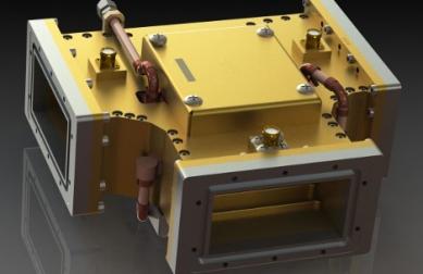
Hzbeat High-Power Waveguide Isolator for radar/SATCOM transmitters. Image © Hzbeat. Source: hzbeat.com.
2.Satellite Communications (Gateway & Payload)
Ka-band gateways experience weather-induced fading and radome moisture. Co-sited uplink chains benefit from connectorized coaxial or waveguide isolators that maintain transmitter stability while outdoor units see temperature cycling. For payloads, low-loss solutions preserve EIRP and reduce TWT/SSPA stress.
3.5G/6G RAN & Backhaul
Small cells and massive-MIMO radios push high PAR (peak-to-average-ratio) waveforms. SMT microstrip isolators offer compact PA protection in front-end modules; at E-band backhaul, waveguide units combine low loss with robust peak handling, keeping links stable during antenna ice or misalignment.
4.Test & Measurement
In PA characterization benches, isolators preserve the source match and protect drivers from device-under-test excursions. Connectorized coaxial units simplify re-configurations across bands.
Selection Checklist (Fast Path)
- Mismatch to guard: define worst-case VSWR (e.g., 3:1) and estimate reverse power envelope (CW + peaks).
- IL budget: confirm allowed dB and thermal rise inside the module.
- Isolation target: set a floor (≥18–20 dB) and evaluate stability margins.
- Power handling: ensure termination can safely dissipate reverse peaks (pulse width/duty cycle aware).
- Form factor: pick SMT/Drop-in vs. Coaxial vs. Waveguide by integration & power needs.
- Environment: temperature, vibration, and moisture conditions drive packaging choices.
Hzbeat Product Highlights
Hzbeat’s isolator portfolio spans 20 MHz to 200 GHz with microstrip/SMT, drop-in, coaxial, and waveguide options, covering S/C/X/Ku/Ka up to D/F bands. Customization includes direction (CW/CCW), dimensions, connector types, and power terminations to suit PA protection envelopes. Explore: Microstrip, Drop-in, Coaxial, Waveguide.
.jpg)
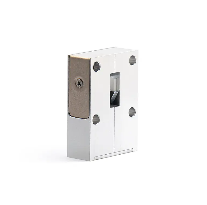
Hzbeat Typical Coaxial Isolator — connectorized convenience with robust reverse-power termination. Image © Hzbeat. Source: hzbeat.com.
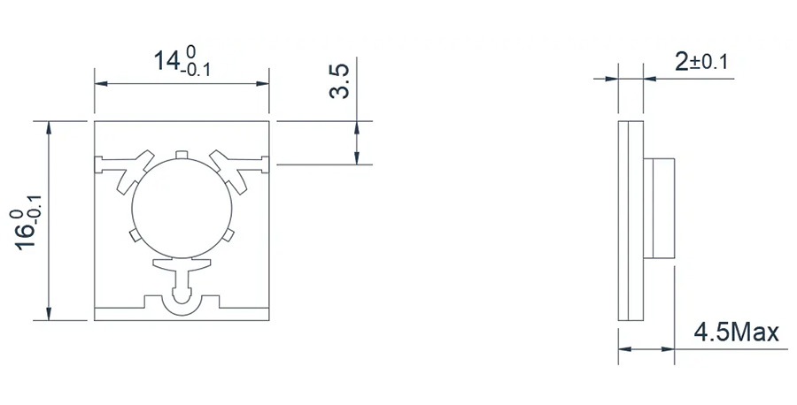
Typical Microstrip Isolator outline (2.7–4.0 GHz). Useful for mechanical integration & thermal modeling. Image © Hzbeat. Source: hzbeat.com.
FAQ
Q1: What happens if a PA operates without an isolator?
Reverse energy created by antenna mismatch returns to the PA, worsening gain compression, EVM/ACLR, and thermal stress. Under severe VSWR, voltage/current excursions can exceed safe operating limits and cause failure. An isolator reduces reverse power and stabilizes the PA’s load line over frequency and temperature.
Q2: How do I size power handling?
Start with worst-case reflected power (consider both CW and peak). Account for modulation PAR or pulse duty cycle. Confirm the termination’s thermal path in the intended enclosure. Coaxial/waveguide parts are preferred when reverse peaks are large or continuous.
Q3: What bands do Hzbeat isolators cover?
From VHF/UHF through S/C/X/Ku/Ka to mmWave bands including D/F-band, with packaging across SMT, drop-in, coaxial, and waveguide to match integration and power needs. See the category links above for detailed model tables.
Contact Hzbeat for Custom RF Solutions
Need a protection path tailored to your transmitter? Share your PA load-pull, mismatch profile, power envelope, and mechanical stack-up — we’ll recommend an isolator with the right IL/Isolation, termination rating, and packaging for your band.
Relateds


About the Author

HzBeat Editorial Content Team
Sara is a Brand Specialist at Hzbeat, focusing on RF & microwave industry communications. She transforms complex technologies into accessible insights, helping global readers understand the value of circulators, isolators, and other key components.