What Is a Drop-In Circulator and Its Function? | HzBeat RF Solutions
Updated on:
Keywords: content="drop-in circulator, embedded circulator, PCB-mounted circulator, compact ferrite circulator, RF circulator, microwave isolator, non-reciprocal device, 5G RF front-end, radar T/R module, satellite ground station, HzBeat"
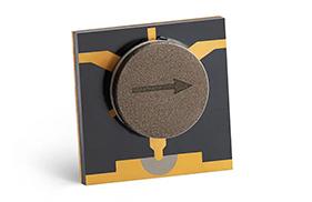
Drop-in circulators—also called embedded or PCB-mounted circulators—are compact ferrite-based non-reciprocal three-port components that route RF energy in a single rotational direction (port 1 → port 2 → port 3 → port 1). Their role is fundamental in radar T/R modules, 5G radios, satellite terminals, and precision microwave test setups, where designers need low insertion loss in the forward path and strong isolation in the reverse path. As RF front ends push toward integration and miniaturization, the drop-in format offers the best balance of electrical performance, size, and manufacturability.

1) Definition: What Exactly Is a Drop-In Circulator?
A drop-in circulator is a three-port ferrite component that enforces unidirectional energy flow around a junction. Unlike coaxial circulators that terminate with connectors, drop-in devices are designed to be embedded within a higher-level module or bolted into a cavity with low-inductance transitions to the surrounding circuitry. The format reduces interconnect parasitics, saves space, and simplifies system assembly, making it popular in phased-array T/R modules, compact 5G radio heads, and instruments where board-level integration matters.
In common usage you will also see embedded circulator, PCB-mounted circulator, or compact ferrite circulator—all pointing to the same mechanical/electrical idea: a robust, cavity-style part optimized for direct integration.
2) Structure & Working Principle
The heart of the device is a magnetized ferrite disk at a microstrip/stripline junction. A permanent magnet (or an external bias field) sets the operating point; the ferrite’s gyromagnetic properties then induce a phase progression that steers power to the next port. Key building blocks include:
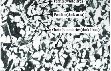
- Ferrite element (often garnet): determines frequency range, loss, and temperature behavior.
- Center conductor geometry (e.g., Y-junction, stripline puck): defines the coupling and bandwidth.
- Bias magnet & return path: sets the non-reciprocal response; shield design contains stray fields.
- Metal housing: offers mechanical rigidity, ground reference, and thermal conductivity.
When a signal enters Port 1, the biased ferrite shifts the phase such that the wave exits Port 2 with minimal loss, while Port 3 sees high attenuation. This circulation repeats for other ports, forming the familiar 1→2→3→1 rotation. If one port is terminated with a matched load, the component acts as an isolator (one-directional device) that absorbs reflections to protect upstream power amplifiers or delicate LNAs.
Tips:
Design note. Ferrite saturation, linewidth, and bias-field uniformity strongly influence insertion loss and isolation. Mechanical tolerances (air gaps, screw torque, lid pressure) also shift S-parameters—hence the need for careful assembly and tuning.3) Package, Mounting, and Integration Nuances
Drop-in circulators are typically square or rectangular metal-cased parts with flush RF apertures on the sidewalls or bottom launch pads. They are attached using screws to a metallic baseplate for thermal sinking and repeatable grounding. RF transitions are kept short to limit parasitics; designers often use shim transitions or gold-ribbon bonds to land precisely at the target impedance. Keepouts are reserved for the magnet and for any stray flux mitigation (steel slug, top cover material, or mu-metal shield).
- Planarity & pressure control ensure uniform ferrite contact and stable resonance.
- Thermal interface material (TIM) reduces junction-to-base thermal resistance.
- EMC hygiene—continuous ground, short return paths—improves port match and isolation.
- Magnetic compatibility: avoid placing magnetically sensitive components too close to the housing.
4) Key Electrical Parameters & Typical Targets
| Parameter | Typical Target | Engineering Notes |
|---|---|---|
| Frequency Range | 2–40 GHz (band-specific) | Set by ferrite material, puck size, junction geometry, and bias field. |
| Insertion Loss | < 0.25–0.35 dB | Forward path loss; sensitive to ferrite Q, conductor loss, and assembly tolerances. |
| Isolation | > 20–25 dB | Reverse leakage suppression; tuning and shielding are decisive. |
| Return Loss (each port) | > 18–20 dB | Good match reduces ripple and improves effective system NF/PA linearity. |
| VSWR | < 1.25:1 | Indicator for impedance conformity at the target band. |
| Average Power | Up to ~100 W CW | Thermal path, ferrite saturation, and housing material set the ceiling. |
| Peak/Surge | Band-specific | Short-duty pulses may be higher; verify energy and cooldown. |
| Operating Temp | -40 to +85 °C (typ.) | High-rel options extend beyond; check magnet and adhesive specs. |
For many system architects, the trade-off is between ultra-low loss and wideband isolation. Practical designs target a sweet spot that minimizes PA heat while still meeting the receiver’s linearity and desense requirements.
5) Selection Guide: How to Pick the Right Drop-In
- Band & bandwidth. Define center frequency and required fractional bandwidth. Wider bands may incur slightly higher IL or a larger footprint.
- Power budget. Estimate worst-case forward and reflected power. Include mismatch scenarios and environmental temperature for derating.
- Isolation goal. Determine how much reverse suppression is necessary to protect LNAs or to reduce PA-induced RX desense.
- Size & mounting. Confirm cavity space, screw positions, bond-pad accessibility, and keepouts for magnets and shields.
- Thermal path. Ensure TIM selection and baseplate flatness achieve safe ferrite temperature under CW conditions.
- Reliability level. For aerospace/defense, consider screening (burn-in, thermal shock, vibration) and magnet aging specs.
Tips:
Rule of thumb. If your PA is marginal on efficiency, prioritize the lowest achievable insertion loss; each 0.1 dB saved directly reduces heat and improves EIRP.6) Applications: Where Drop-In Circulators Shine
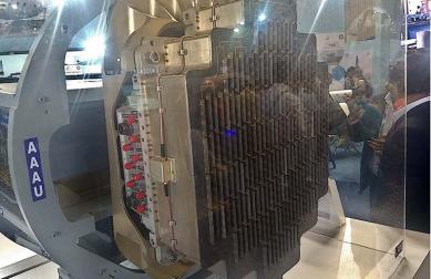
- Radar & EW: Protecting receiver chains in T/R modules; handling high peak power while keeping noise figure low.
- 5G/6G RAN: Integrating with compact radio heads and massive-MIMO beamforming modules, reducing cabling loss versus coax units.
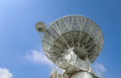
- Satellite terminals: Ensuring uplink PAs do not back-drive sensitive LNBs; improving duplexing in compact gateways.
- Test & Measurement: Stabilizing test ports during S-parameter sweeps to isolate instrument reflections.
- Industrial/Energy/Medical: Plasma sources, MRI sub-assemblies, and scientific drivers requiring directional control.
7) Comparison vs. Coaxial, SMT/Microstrip, and Waveguide Types
Coaxial circulators are connectorized and flexible for bench setups but add interconnect loss/volume. SMT/Microstrip circulators are smallest and ideal for automated assembly yet may have stricter thermal and power limits. Waveguide circulators excel at very high power and narrowband low-loss links but are physically larger. The drop-in format sits between them—achieving low loss and high integration with excellent mechanical robustness and serviceability.
- When to choose drop-in? Moderate-to-high power, board-level integration, and repeatable RF transitions without external connectors.
- When not? Ultra-miniature SMT constraints or extreme peak power requiring waveguide hardware.
8) Integration Playbook: Thermal, Magnetic, and Tuning
- Thermal. Use a flat, lapped base with TIM (e.g., graphite or silicone pads). Verify case temperature at max EIRP and worst VSWR.
- Magnetic. Respect keepouts; add steel shields when nearby sensors drift. Mind compass/IMU behavior in drones/robots.
- EM Layout. Short, wide ground returns; avoid vias-in-pad unless filled/planarized. Ribbon bonds reduce inductance.
- Tuning. Manufacturer shims and lid torque specs matter; replicate assembly torque in production for consistent S-parameters.
- Environmental. Temperature cycling can shift bias; consider margins for cold-soak and hot-soak scenarios.
9) Testing & Reliability
Qualification typically covers return-loss, insertion-loss, and isolation across temperature and bias tolerance, followed by power-handling tests. For high-rel programs, add thermal shock, vibration, salt fog (naval), and magnet aging. In production, maintain golden units and correlation procedures between benches. Record lid torque and thermal interface changes as controlled variables.
In system verification, test out-of-band behavior, because adjacent-band ripple can interact with filters and mixers. Also evaluate reverse power under fault (e.g., antenna disconnection) to ensure the isolator mode absorbs energy safely.
10) Cost, Lead Time, and Customization
Compared with connectorized components, drop-in circulators reduce recurring cable/connector costs and simplify assembly. Lead times depend on ferrite supply, magnetization steps, and machining capacity. Most vendors—including HzBeat—offer custom tuning for center frequency, bandwidth, isolation targets, temperature class, and mounting hole patterns. Small-batch prototyping is recommended to converge on the exact thermal path and assembly torque before ramp.
Conclusion
Drop-in circulators deliver an exceptional mix of low insertion loss, high isolation, and mechanical robustness in an embedded format that fits today’s space- and power-constrained RF designs. Whether labeled as embedded, PCB-mounted, or compact ferrite circulator, the concept remains the same: dependable one-way signal flow that protects front-end components, stabilizes duplex paths, and preserves system linearity across temperature and tolerance. With careful attention to thermal interfaces, magnetic keepouts, and assembly torque, a modern drop-in circulator becomes a quiet guardian of performance in radar, cellular infrastructure, and satellite communications.
FAQ
Q1. Is a drop-in circulator the same as an isolator?
No. A circulator has three ports and circulates energy 1→2→3→1. If you terminate one port in 50 Ω, it behaves as a one-directional isolator.
Q2. What is the advantage over coaxial circulators?
Lower interconnect loss, smaller volume, and tighter integration. Coaxial versions are flexible for lab setups but add connector/cable parasitics.
Q3. Can it handle high power?
Yes—provided the thermal path is engineered. With good baseplate conduction and realistic VSWR margins, drop-ins can manage up to ~100 W CW in many bands.
Q4. How sensitive is it to temperature?
Ferrite and magnet materials shift slightly with temperature. Vendors design for stable bias; engineers should validate cold/hot extremes.
Q5. What mounting mistakes cause failures?
Non-planar bases, insufficient torque, poor TIM application, long inductive bonds, and ignoring magnetic keepouts are frequent culprits.
References
- R. E. Collin, Foundations for Microwave Engineering, 2nd ed., McGraw-Hill.
- IEEE Transactions on Microwave Theory and Techniques (MTT).
- Microwave Ferrites and Non-Reciprocal Devices — classic application notes and vendor design guides.
- HzBeat Drop-In Circulator Product Series, 2025.
Relateds

About the Author

HzBeat Editorial Content Team
Marketing Director, Chengdu Hertz Electronic Technology Co., Ltd. (Hzbeat)
Keith has over 18 years in the RF components industry, focusing on the intersection of technology, healthcare applications, and global market trends.