Why Choose a Waveguide Circulator
Updated on:
Keywords: waveguide circulator, RF circulator, microwave circulator, high-power RF, HzBeat
A waveguide circulator is the preferred RF circulator when your architecture demands high-power RF handling, ultra‑low insertion loss, and stable isolation over temperature. Below we unpack the physics, the design and materials, how it compares with other microwave circulator types, and where it shines in real systems.
1) Introduction
In radar, satcom gateways, deep‑space links, and millimeter‑wave test stands, protecting front‑ends and managing duplex paths depend on non‑reciprocal components. A waveguide circulator routes energy sequentially between ports with very low loss while maintaining high reverse isolation. Unlike planar transmission lines, metallic rectangular waveguides propagate low‑attenuation modes (typically TE10) and offer generous surface area for heat spreading, enabling robust operation at X‑, Ku‑, K‑, and Ka‑bands under demanding average and peak power.
2) What Is a Waveguide Circulator?
A circulator is a passive, non‑reciprocal three‑port junction directing power 1→2, 2→3, and 3→1. In ferrite implementations, the effect originates from the gyromagnetic precession of a magnetized ferrite puck in a static bias field. Inside a precision‑machined cavity, the ferrite couples to the rotating RF magnetic field; with correct bias and geometry, the junction establishes a 120° phase progression that yields circulation with low insertion loss and useful bandwidth.
Design levers: saturation magnetization (Ms), dielectric constant (εr), resonance linewidth (ΔH), bias margin, tuner topology, cavity symmetry, and temperature coefficients. Each lever trades isolation, bandwidth, and physical size.
3) Key Advantages of Waveguide Circulators
High‑Power Margin with Low Loss
Rectangular waveguides exhibit low conductor loss and high breakdown thresholds. Well‑designed units routinely achieve sub‑dB insertion loss while tolerating kilowatt‑class peak powers and high duty cycles—ideal for radar transmit chains and HPA interfaces.
Excellent Isolation and Stability
With appropriate ferrites and magnet assemblies, 20–30+ dB isolation is practical over wide bands. Mechanical rigidity of the waveguide housing preserves symmetry, keeping isolation and VSWR stable across vibration and temperature cycling.
Low VSWR and Clean Matching
Standard waveguide interfaces (e.g., WR‑90, WR‑75, WR‑62) and tuner elements permit low return loss across the passband, minimizing reflections into sensitive LNAs and high‑gain PAs.
Harsh‑Environment Reliability
All‑metal construction, robust magnet biasing, and proven ferrite physics deliver long field life in airborne, maritime, and outdoor gateway installations.
4) Waveguide vs. Other Circulator Types
Versus Microstrip
Microstrip/stripline circulators are compact and economical at low‑to‑moderate power. At higher microwave bands, dielectric and conductor losses rise and thermal density becomes limiting. Waveguide circulators offer lower attenuation and much higher thermal headroom.
Versus Drop‑In
Drop‑ins integrate easily inside modules and excel up to mid‑microwave bands. For very high peak/average power, the larger aperture and metallic walls of waveguide units spread heat and keep field strengths below breakdown thresholds.
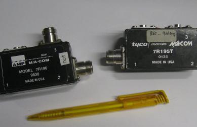
Versus Coaxial
Coaxial circulators provide convenient connectorized coverage and good bandwidth. At mm‑wave and high power, rectangular waveguides generally win on attenuation, isolation robustness, and power handling.
5) Design and Materials of Waveguide Circulators
Ferrite Core & Magnetic Biasing
Low‑loss garnet or spinel ferrites (including YIG variants) are magnetized using permanent magnets or electromagnets. The parameters Ms, εr, and ΔH govern resonance, junction size, insertion loss, and temperature drift. Designers allocate bias margin to avoid isolation collapse over temperature and aging.
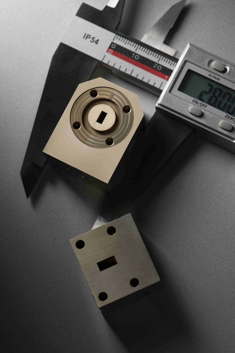
Waveguide Cavity & Precision Machining
Housings are CNC‑machined aluminum or copper with plated interiors to minimize skin loss. Short‑wall modifications, tuning screws, and dielectric posts flatten the passband and reduce sensitivity to assembly tolerances. Tight flatness and repeatable torque are critical to preserve field symmetry.
Thermal & Mechanical Considerations
High‑power RF dissipates heat in ferrites and metal walls. Designs add thick bases, conduction paths to the chassis, and—when necessary—heat spreaders. Mechanical alignment and magnet shimming keep the junction centered, stabilizing isolation and return loss under shock and thermal cycling.
Engineering checklist: target band & guide size (e.g., WR‑90 for 8.2–12.4 GHz); isolation target (>20 dB); insertion loss (sub‑dB); average/peak power & duty; ferrite selection (Ms, εr, ΔH); magnet topology; thermal path; environmental sealing.
6) High‑Performance Applications
- Radar (X/Ku/K/Ka): Duplexing in T/R modules; protects LNAs during high‑power transmit bursts while keeping insertion loss minimal to preserve EIRP.
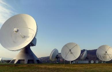
- Satellite Earth Stations: Low‑loss routing between HPAs, OMTs, and feed networks, improving uplink margins and maintaining stable isolation.
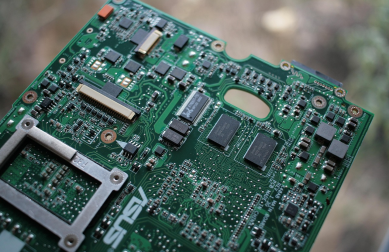
- 5G/6G mmWave: FR2 infrastructure and test fixtures benefit from the low loss and thermal resilience of waveguide components under elevated power.
- High‑Power Test & Instrumentation: Combiner networks, magnetron injection‑locking, and accelerator drives require robust non‑reciprocity and heat handling.
7) About HzBeat
HzBeat engineers and manufactures waveguide circulator solutions across wide bands from 20 MHz to 200 GHz. Our portfolio includes low‑loss ferrite junctions, custom magnet assemblies, and precision CNC housings optimized for high‑power RF service in radar, satcom, and instrumentation. Explore current offerings and customization:
8) Conclusion
When your RF chain must minimize loss and heat at microwave bands while sustaining high average or peak power, a waveguide circulator provides the cleanest attenuation profile, strongest thermal margins, and most reliable isolation. With correct ferrite selection, bias margin, and mechanical symmetry, you protect PAs and LNAs, stabilize duplexers, and preserve link budgets in the harshest environments.
9) FAQ
- What frequency ranges are typical?
- Standard rectangular waveguides (e.g., WR‑90, WR‑75, WR‑62) cover X‑/Ku‑/K‑/Ka‑bands. Custom designs focus on sub‑bands to push isolation and reduce insertion loss.
- How is a waveguide circulator different from coaxial or microstrip types?
- Waveguide offers lower attenuation and higher power/thermal margins at high frequency. Coaxial and microstrip favor compactness and ease of integration at lower power.
- Can HzBeat customize for peak power or extreme temperature specs?
- Yes. We tune ferrite materials, magnet topology, and cavity mechanics for specified peak/average power, duty cycle, and environmental conditions.
Relateds

About the Author

HzBeat Editorial Content Team
Marketing Director, Chengdu Hertz Electronic Technology Co., Ltd. (Hzbeat)
Keith has over 18 years in the RF components industry, focusing on the intersection of technology, healthcare applications, and global market trends.