Future of D-Band and Millimeter Wave: Microwave Market Outlook for RF Circulators, Isolators, and 5G/6G
Updated on:
Keywords: D-band microwave, millimeter wave, high-power RF circulator, RF isolator market, Ka-band, satellite communication, defense radar, 6G, automotive radar, SMT isolator, insertion loss, isolation,
TL;DR Ka-band still carries a huge load, but spectrum pressure and system ambitions are pushing designs toward the D-band frontier. Teams that align frequency choice with low-loss/high-isolation components and AI-ready spectrum control will pull ahead.
Table of Contents
- Introduction: frequency choice is now a strategic lever
- Trend 1 — From Ka to D‑band: a practical spectrum evolution
- Trend 2 — Demand spikes for high‑power, low‑loss building blocks
- Trend 3 — AI‑driven spectrum intelligence and adaptive operation
- Trend 4 — Cross‑industry expansion: radar, imaging, inspection
- How to pick a frequency (and not regret it later)
- Summary & Outlook
- Frequently Asked Questions (FAQ)
- References & further reading
Introduction: frequency choice is now a strategic lever
In modern communications and defense electronics, frequency is no longer an afterthought delegated to the RF team at the end of a project.
It is a strategic lever that directly shapes capacity, resilience, BOM cost, and regulatory risk.
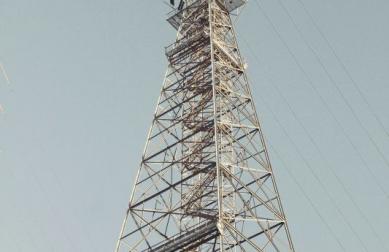
Over the past decade, Ka‑band (26.5–40 GHz) and E‑band (60–90 GHz) shouldered much of the growth in satellite broadband and 5G backhaul, aided by massive investment in front‑end chipsets, packaging, and system integration.
Yet the physics has remained stubborn: rain attenuation, multi‑path dynamics, interference density, and the finite nature of contiguous spectrum have created a squeeze.
As multi‑orbit constellations expand and terrestrial densification continues, engineering and policy communities are looking higher—toward the millimeter‑wave domain and, inside it, the uniquely promising D‑band window (110–170 GHz).
Why D‑band? First, sheer spectral real estate: tens of gigahertz of relatively clean territory that can enable sub‑terabit wireless links over short to medium distances.
Second, sensing performance: shorter wavelengths yield finer spatial resolution for industrial inspection and emerging medical modalities.
Third, architectural flexibility: with careful link budgeting and packaging, D‑band can act like a wireless "backplane," reducing cable runs in vehicles, factories, or data centers.
Of course, none of this comes free—loss budgets tighten, thermal density climbs, and passive component quality becomes a gating factor.
This article surveys four structural forces pushing systems upward and translates them into concrete design implications for teams building the next wave of microwave and mmWave products.
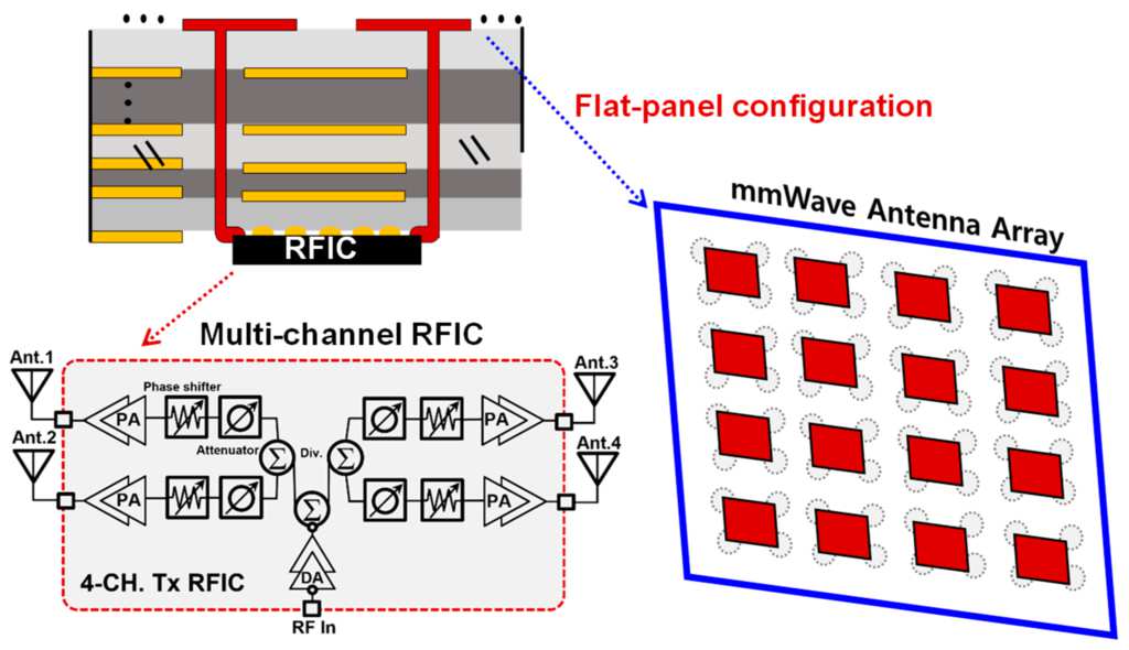
Source: Adapted from [Author], Sensors (MDPI), CC BY 4.0.
Trend 1 — From Ka to D‑band: a practical spectrum evolution
Why D‑band matters
Ka‑band remains indispensable.
Its ecosystem is deep, equipment is broadly available, and the path‑to‑market is relatively clear.
But it is increasingly crowded.
Aggregated traffic forecasts suggest 10–20× demand growth over the coming decade, while the number of independently operated networks (GEO, MEO, LEO) multiplies.
Coexistence pressures are not merely academic: side‑lobe management, pointing tolerances, cross‑polar interference, and rain‑fade mitigation eat margin that would otherwise support higher‑order modulation or user density.
As a result, R&D is moving toward D‑band, where contiguous spectrum blocks enable clean channelization, and directional antennas at short ranges can push spectral efficiency without violating interference budgets.
Regulators and standards bodies are engaging.
ETSI TR 103 498 puts 120–260 GHz on the study map for Europe, including the 110–170 GHz D‑band window; in the U.S., the FCC has opened experimental activity around 116–123 GHz and 174.8–182 GHz.
Academic and industrial consortia are publishing link‑budget studies that treat D‑band as a near‑term candidate for backhaul, campus networks, and intra‑vehicle links.
The link budgets are realistic rather than utopian: ranges of tens to a few hundreds of meters at fiber‑like throughput, assuming careful antenna gain, alignment, and fade margin management.
Where D‑band fits: high‑throughput short/medium links (last‑hundred‑meters access); fine‑resolution sensing in the 120–150 GHz region; and backplane‑like connectivity inside vehicles and data centers.
It complements—rather than replaces—Ka/Ku/E‑band deployments, giving architects a new knob to balance capacity, availability, and deployment cost.
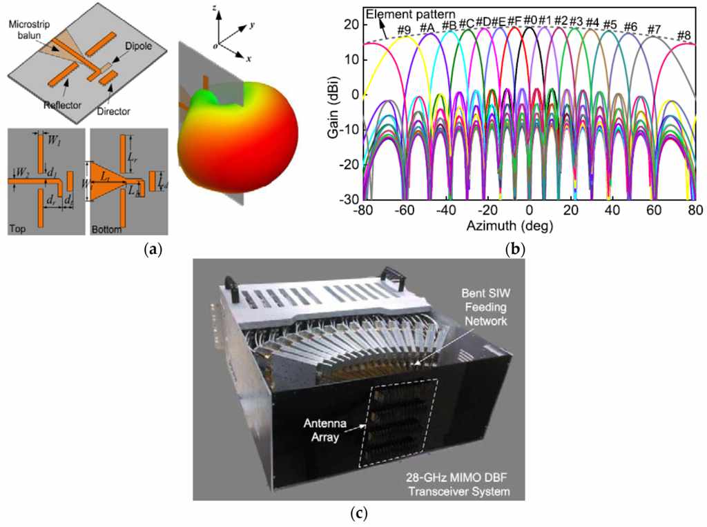
Source: Adapted from [Author], IEEE Access / MDPI, CC BY 4.0.
Trend 2 — Demand spikes for high‑power, low‑loss building blocks
Key performance benchmarks
As systems climb in frequency, fundamentals get unforgiving.
Conductor and dielectric losses rise; packaging parasitics become first‑order; connectors and transitions must be treated as design elements rather than afterthoughts.
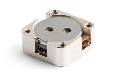
Two metrics dominate front‑end viability: Insertion Loss (IL) and Isolation.
Keep IL low and flat across bandwidth, and your power budget, EVM, and link margin stay healthy.
Keep isolation high, and your T/R chains are protected against self‑inflicted wounds—PA reflections, LNA desensitization, and oscillation risk under temperature and vibration.
In practice, many programs target <0.5 dB IL and >20 dB isolation across their operating slice, with ≥100 W power handling in high‑duty radar or protected satcom chains.
Achieving this in compact modules requires a portfolio approach: waveguide or drop‑in devices for peak power paths, coaxial circulators for ruggedized testbeds and gateways, and SMT/microstrip isolators for dense front‑ends where board‑level integration wins the thermal and size battle.
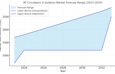
Market signals reinforce the engineering reality.
Analyses predict ~7–8% CAGR for high‑power RF devices into the 2030 timeframe, with circulators and isolators accounting for a meaningful slice of spend.
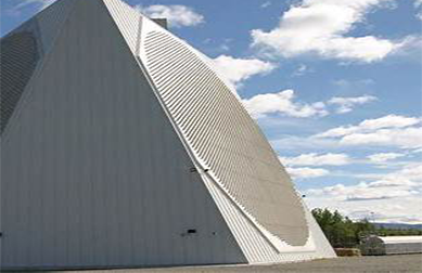
Defense radar upgrades (including AESA retrofits), civil aviation surveillance refreshes, and multi‑band satellite gateways are among the steady buyers.
On the commercial side, fixed wireless and private 5G/6G campus networks require front‑ends that can switch bands while keeping linearity and efficiency in check—again raising the bar for passives that quietly hold the system together.
Design checklist at 100+ GHz: treat transitions as components; minimize via stubs and uncontrolled cavity modes; co‑design heat spreaders with RF; qualify parts for shock and thermal cycling; and pick families of circulators/isolators that scale across bands so your PCB footprints don’t have to.
Trend 3 — AI‑driven spectrum intelligence and adaptive operation
AI in practice
Static channel plans fail in dense, heterogeneous RF environments.
Machine‑learning‑based spectrum sensing, aided by compact RF front‑ends, enables predictive interference avoidance, real‑time channel re‑allocation, and QoS‑aware link shaping.
In radar, deep networks reduce false alarms and improve target classification when paired with high‑quality, stable RF chains.
In satellite networks, AI can coordinate handovers across bands and orbits, balancing rain fade risk against throughput goals.
In industrial IoT, reinforcement learning agents learn occupancy patterns and nudge devices into cooperative behavior.
For hardware teams, the implication is clear: the control plane is getting smarter, but the data plane must be wideband, low‑loss, fast‑settling, and linear.
Circulators and isolators become the “circuit breakers” that let software take risks with channel switching without destroying PAs or desensitizing LNAs.
Low group delay ripple, predictable thermal drift, and repeatable S‑parameters are as important as headline IL/Isolation numbers when the network hops bands under load.
As AI control loops shorten, you may face non‑obvious interactions: PA protection thresholds clashing with retune transients; calibration sequences lengthening boot times; or beam‑forming codebooks that assume static passives.
Good news: component choices mitigate much of this—wideband isolators with flat IL; circulators with robust return loss; packages that stay linear as junctions heat.
In other words, pick parts that behave well while software experiments.
Trend 4 — Cross‑industry expansion: radar, imaging, inspection
Emerging application domains
mmWave’s first mass market was automotive ADAS around 77–81 GHz.
That ecosystem is now maturing: integration levels are rising, costs are falling, and Tier‑1s are experimenting with higher‑frequency sensing modes for tighter angular resolution and multi‑modal fusion with cameras and LiDAR.
In parallel, security imaging and industrial non‑destructive testing are quietly adopting 100+ GHz windows where shorter wavelengths sharpen feature extraction on composites, plastics, and biological tissues.
Emerging medical modalities at 120–150 GHz offer non‑ionizing, high‑contrast imaging opportunities when paired with careful power management and safety protocols.
These verticals lead to concrete product requirements.
Automotive and portable medical platforms demand SMT/microstrip form factors for passives to keep assemblies dense and automated.
Ruggedized gateways and testbeds still rely on coaxial variants for connectorized flexibility, while waveguide/drop‑in devices remain the right answer for the highest‑power chains.
The unifying theme is predictable thermal behavior and repeatable RF over lifetime environmental stress.
How to pick a frequency (and not regret it later)
-
Start with the link budget. Define range, throughput, availability targets, and acceptable outage.
D‑band excels at short/medium ranges with extreme capacity; Ka/Ku/E may remain the right choice for longer links with strict availability.
-
Check spectrum access early. Unlicensed 60 GHz is flexible in many markets; 110–170 GHz is under active study—secure trials and understand local power/EIRP/antenna rules before committing hardware.
-
Design to thermal reality. Power density rises with frequency.
Model junction temps, use low‑loss passives, and budget for airflow or spreaders in enclosure constraints.
-
Engineer for agility. Assume interference and plan for retunes.
Specify wideband components that keep IL flat and isolation high across adjacent channels.
-
Prototype with production‑grade parts. Avoid footprint churn: choose circulator/isolator families that scale across bands so a late frequency pivot doesn’t force a mechanical redesign.
Summary & Outlook
The movement toward D‑band is not a stunt; it is a pragmatic response to spectrum scarcity, capacity ambitions, and the physics of sensing.
Ka‑band will continue to do heavy lifting, but the combination of new spectral real estate, finer spatial resolution, and architectural flexibility makes D‑band a serious option across communications and sensing.
Success demands a systems view: align frequency choice with link budgets, component quality, packaging, and control‑loop intelligence.
- Spectrum trajectory: Ka remains vital; D‑band is the new frontier for ultra‑high throughput and high‑resolution sensing.
- Device prerequisites: Winning chains keep IL low/flat, isolation high, and thermal behavior predictable at 100+ GHz.
- Intelligence in the loop: AI will pressure passives to be wider, cleaner, and faster to settle as networks retune on the fly.
- Domain convergence: Communications, radar, imaging, automotive, and medical will overlap; interference and synergy will co‑evolve.
Choose frequencies not only for today’s bandwidth but for tomorrow’s ecosystem.
With the right RF circulators, isolators, and adaptive intelligence, frequency choice becomes a durable advantage.
Frequently Asked Questions (FAQ)
Q1: Why not keep pushing Ka‑band instead of moving to D‑band?
Ka‑band faces spectrum crowding, rain‑fade constraints, and limited contiguous channels for the next order‑of‑magnitude capacity jump.
D‑band offers fresh spectrum for short/medium links with careful link budgets.
The bands complement each other.
Q2: What performance benchmarks should I expect from D‑band circulators/isolators?
Common targets are <0.5 dB insertion loss, >20 dB isolation, and ≥100 W power handling for demanding radar/satcom chains.
Flatness, group delay, and thermal drift stability matter as much as nominal IL/Isolation.
Q3: How mature are global regulations for 110–170 GHz?
Variation is the rule.
Confirm local EIRP, antenna, and safety rules before committing to BOMs.
Q4: Will AI/cognitive radio materially improve mmWave/D‑band?
Yes—predictive interference avoidance and dynamic allocation can recover meaningful capacity and reduce dropouts.
Hardware must be wideband, low‑loss, linear, and thermally stable to support rapid retunes.
Q5: Can existing mmWave systems be upgraded to D‑band?
Antennas, interconnects, packaging, and passives typically need re‑work.
Migrate via well‑scoped prototypes using component families that footprint‑match across bands.
Q6: What materials/platforms enable low‑loss D‑band passives?
Ferrite materials remain foundational for circulators/isolators.
GaN/SiC push active device power density; LTCC and advanced laminates help tame loss and CTE.
Package design is as decisive as material choice.
Q7: Which industries will adopt D‑band first?
Early movers: satellite gateways and defense radar.
Fast followers: automotive radar variants and medical/industrial imaging as regulations and component supply stabilize.
References & further reading
- ETSI TR 103 498: Spectrum considerations at 120–260 GHz (includes D‑band context).
- FCC 47 CFR §15.255 and related experimental provisions near 116–123 & 174.8–182 GHz.
- IEEE Spectrum (2024): “D‑Band and Beyond for 6G Communications.”
- Microwave Journal (2025): “Four Innovative Trends Reshaping the Microwave Radio Market.”
- Allied Market Research (2024): High‑Power RF Devices Market Forecast 2024–2030.
- Markets&Markets (2024): Automotive Radar Market Outlook 2024–2032.
- Wikimedia image credits per figcaptions; retain attribution when deploying.
- Flat-panel mmWave antenna schematic. Adapted from: [Author], Sensors (MDPI), 2023. Licensed under CC BY 4.0.
- Antenna array structure and gain patterns. Adapted from: [Author], IEEE Access, 2022. Licensed under CC BY 4.0.
Relateds
About the Author

HzBeat Editorial Content Team
Marketing Director, Chengdu Hertz Electronic Technology Co., Ltd. (Hzbeat)
Keith has over 18 years in the RF components industry, focusing on the intersection of technology, healthcare applications, and global market trends.