High-Power RF Circulator Performance Under -55°C to +85°C Conditions
A technical news report on high-power RF circulator performance across -55°C to +85°C: insertion loss, isolation, VSWR, power handling, thermal cycling validation, failure modes, and design strategies for harsh environments.
What This News Covers
A high-power RF circulator is often treated as “just a protection component,” but across -55°C to +85°C it becomes a system-level stability device. Temperature changes can shift ferrite permeability, magnetic bias conditions, junction matching, mechanical dimensions, and even solder joint behavior—each one capable of degrading isolation, increasing insertion loss, or raising VSWR.
This article explains how to interpret temperature performance claims, how test labs validate them, what failure modes show up first, and which design levers provide the most reliable improvement without sacrificing power handling.
1) Introduction: Why Temperature Specs Matter
In modern transmitter chains, a high-power RF circulator is not simply an accessory—it is an insurance policy that must work when everything else is stressed: supply rails drift, power amplifier efficiency changes, antennas de-ice imperfectly, connectors breathe, and the environment swings from deep cold to sustained heat.
The operating temperature range of -55°C to +85°C is widely used in harsh environment design requirements because it captures two realities: (1) systems are expected to start cold without “warm-up excuses,” and (2) systems are expected to survive elevated internal heating even when ambient temperature is already high. For components like RF circulators, the physics is more sensitive than many engineers initially assume. Ferrite properties shift with temperature. Permanent magnets drift. Mechanical tolerances move. Thermal interfaces change. Each shift is small, but the circulator is a three-port device that depends on tight balance—so small changes can cause large RF penalties.
2) Why -55°C to +85°C Is a Baseline in Harsh Environments
The -55°C lower bound comes from long-established aerospace and defense environmental expectations. At high altitude, in desert nights, or on cold-start platforms, electronics can see extremely low temperatures. Meanwhile, +85°C is a common upper bound for outdoor electronics, industrial enclosures, and board-level reliability. Even if ambient does not reach +85°C, high-power operation can push internal temperatures near that threshold due to self-heating.
In these cases, the high-power RF circulator must preserve core behaviors: stable circulation direction, sufficient isolation to protect the power amplifier, low insertion loss to maintain efficiency, and acceptable VSWR to prevent reflected power from stacking on top of normal load mismatch.
| Scenario | Typical Thermal Stress | Why the RF Circulator Matters | Most Sensitive Metric |
|---|---|---|---|
| Outdoor radar / phased-array panels | Cold start + daytime solar heating | High reflected power events during scan / weather | Isolation drift, VSWR |
| Satellite ground stations | Night cold + power amplifier heat | Protects PA and stabilizes duplex paths | Insertion loss and isolation |
| Aerospace payload RF chains | Low temp at altitude + vibration | Cold start performance must still meet spec | Matching/VSWR, bias margin |
| Industrial high-power transmitters | High ambient + continuous RF load | Thermal management determines long-term stability | Insertion loss and power handling |
3) What Temperature Changes Inside a Ferrite Circulator
Most high-power RF circulators are ferrite-based, using a magnetically biased junction that routes energy from Port 1→2, 2→3, and 3→1 (or the opposite direction depending on bias orientation). That routing relies on a specific operating point—an electromagnetic balance that is influenced by temperature in at least four ways.
3.1 Ferrite material properties drift
Ferrite permeability and magnetic loss parameters change with temperature. This can shift the effective junction behavior: the circulator’s center frequency, bandwidth shape, and the depth of isolation notches can move. The result is often a temperature-dependent isolation profile—your “20 dB isolation” at 25°C may become 16–18 dB near an extreme if the design has insufficient bias margin or if the ferrite formulation is not optimized for wide temperature operation.
3.2 Permanent magnet bias varies with temperature
Magnets have a temperature coefficient. As temperature rises, magnet flux density typically decreases; as temperature falls, it increases. The circulator is therefore exposed to under-bias at high temperature and over-bias at low temperature, depending on the bias design. This effect is a major reason why wide-temperature high-power RF circulator design is not purely a mechanical challenge—it is a bias stability challenge.
3.3 Mechanical expansion and contraction alter matching
Metal housings, ceramic substrates, ferrite disks, and solder joints do not share identical coefficients of thermal expansion. Over repeated cycles, stress concentrates at interfaces. Even before visible damage occurs, micron-level changes can slightly alter the junction geometry and shift impedance matching. That shows up as changes in return loss and VSWR.
3.4 Self-heating interacts with ambient temperature
“+85°C ambient” is not the same as “+85°C junction.” High-power RF operation can elevate internal temperature above ambient depending on thermal resistance and mounting. The practical design question becomes: can the circulator maintain performance when its internal hotspot is meaningfully higher than +85°C? Good qualification plans treat ambient range as the beginning of the story, not the end.
4) Key Metrics Under Temperature: IL, Isolation, VSWR, and Power Handling
Engineers evaluating a high-power RF circulator across -55°C to +85°C should look at four metrics as a set, not individually. Improving one often pushes another in the wrong direction unless the design is balanced.
Insertion Loss (IL)
Expect a small drift with temperature due to conductor loss, ferrite loss, and matching shift. For high-power designs, even +0.05 to +0.15 dB can matter because it translates directly into heat and efficiency loss.
Isolation
The most “temperature-sensitive” spec in many ferrite circulators. It’s a protection metric, not a vanity metric. When isolation falls, reflected power reaches the amplifier and can create instability or damage.
VSWR / Return Loss
Indicates how the circulator loads the system. A VSWR rise at temperature extremes can multiply reflected power events. This is especially risky during cold start when other parts of the system are also drifting.
Power Handling
Must be interpreted with duty cycle, peak, and thermal environment. A “500 W” rating without temperature context can mislead. At high ambient and poor thermal contact, the effective safe power can be lower.
4.1 What “stable performance” really means
In qualification-driven programs, stability is often judged by bounded deltas (drift limits) rather than absolute best-case values at 25°C. A realistic stability framework might include:
- IL drift bound: Keep insertion loss change within a controlled envelope across temperature (e.g., ≤ +0.10 dB worst-case across the band).
- Isolation floor: Maintain a minimum isolation threshold (e.g., ≥ 18–20 dB) across temperature and across the specified frequency band.
- VSWR ceiling: Keep return loss above a defined minimum (or VSWR below a defined maximum) across temperature.
- Power de-rating curve: Provide clear guidance: at high ambient, continuous power may require de-rating unless thermal resistance is improved.
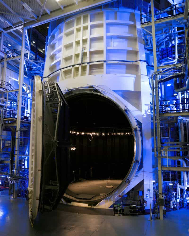
5) Validation Methods: Chamber Cycling + RF Measurement
A credible temperature claim for a high-power RF circulator typically depends on two kinds of evidence: environmental exposure (soak + cycling), and RF measurement at temperature (S-parameters, plus high-power checks when relevant). Testing can be done in steps—starting with low-power VNA checks and then progressing to power stress validation.
5.1 The “soak” principle
Soak means the device is held at temperature long enough to reach thermal equilibrium. Without soak, measurement reflects a transient state rather than true temperature performance. For small packages this may be faster, but high-power housings often require longer soak times due to mass and mounting interfaces.
5.2 VNA-based S-parameter measurement in a chamber
Many labs route coax feedthroughs into the chamber and measure S11/S21/S31. The goal is repeatability and traceability: the same cables, the same calibration method, and consistent torque on connectors to avoid “temperature drift” that is actually a measurement artifact.
5.3 High-power validation: burn-in and stress tests
High-power tests are often separated from VNA work because power amplifiers, loads, and monitoring equipment require their own stability management. Practical high-power validation may include:
- Continuous-wave (CW) stability checks at defined ambient temperatures.
- Pulsed power verification with controlled duty cycle and peak power.
- Forward/reflected power monitoring to detect onset of instability.
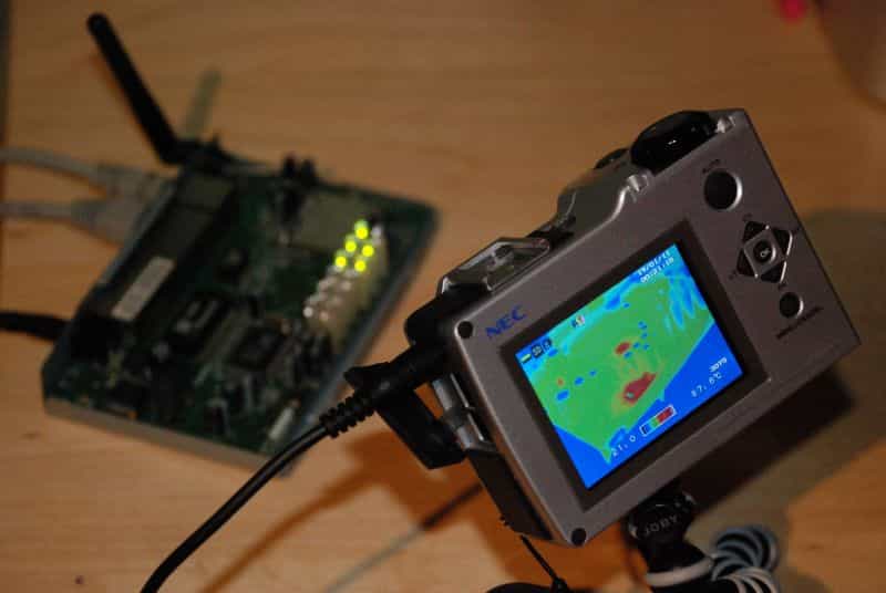
- Temperature rise mapping on the housing and mounting interface to assess thermal path quality.
6) Failure Modes That Show Up First (and Why)
When a high-power RF circulator struggles across -55°C to +85°C, the first symptoms are usually not catastrophic. They are subtle drifts: a few dB of isolation loss at one edge of band, a VSWR rise at one port, or an insertion loss increase that only appears after repeated cycles. Understanding typical failure modes helps engineers ask better questions before a program slips.
6.1 Isolation collapse at one band edge
Often tied to bias margin and ferrite behavior. If the design is “tuned” too tightly at room temperature, the temperature drift can move the isolation notch away from the band edge. The fix may require bias optimization, ferrite selection refinement, or a more temperature-resilient matching approach.
6.2 VSWR rise during cold start
At -55°C, mechanical contraction can shift matching. Connector behavior and solder joint stiffness can also change. Cold start is where the system is least forgiving: the power amplifier may be less linear, the antenna might be ice-loaded, and cables may be stressed. If VSWR rises, the circulator sees more reflected energy, and the entire chain’s stability margin shrinks.
6.3 Solder/interface degradation after cycling
Repeated thermal cycling creates fatigue. In drop-in or board-mounted designs, the interface between terminals and pads can develop microcracks or weakened wetting, particularly if surface finish and solderability control are inconsistent. Over time, this becomes a reliability issue, not just an RF issue.
7) Design & Process Strategies for Wide-Temperature Stability
Strong wide-temperature performance rarely comes from a single improvement. It typically comes from stacking multiple small decisions—material choice, bias design, thermal path engineering, mechanical tolerance control, and consistent manufacturing processes.
7.1 Ferrite and magnet selection with temperature in mind
Ferrite formulation and magnet grade selection influence drift behavior. Designers aim for a bias condition that stays within an acceptable window across temperature: not over-biased at -55°C and not under-biased at +85°C.
7.2 Mechanical tolerance control and CTE-aware architecture
When dissimilar materials are forced together, stress accumulates at interfaces. A wide-temperature mechanical design reduces stress concentration and keeps the RF geometry stable. Even if the RF structure is excellent, inconsistent assembly pressure or interface flatness can introduce unit-to-unit variation that grows at temperature extremes.
7.3 Thermal path: the most underrated feature in high-power RF circulators
For a high-power RF circulator, thermal engineering is RF engineering. Lower insertion loss reduces heat generation, but removing heat is equally critical. A robust thermal path includes:
- Low thermal resistance mounting (flatness, torque, thermal interface materials considered).
- Housing materials and thickness that spread heat without warping.
- Repeatable assembly so every unit has similar contact quality.
7.4 Manufacturing repeatability: process as a performance feature
Wide-temperature stability is often lost not in design, but in variation. If plating thickness, solderability, magnet placement, or junction alignment varies beyond tolerance, the temperature drift becomes unpredictable. Mature vendors treat process control as part of RF performance: it is how you reduce the “tail risk” where a few units drift badly at temperature extremes.
8) Applications Where Wide-Temp Stability Is Non-Negotiable
Not every RF system needs -55°C performance, but when it does, the requirement is typically “hard.” In these systems, the high-power RF circulator is part of a protection strategy that prevents expensive downtime or mission failure.
8.1 Radar transmit/receive chains
Radar systems can experience abrupt changes in load conditions due to environmental effects, scan conditions, or antenna behavior. When isolation drifts low at temperature extremes, reflected power can reach sensitive amplifier stages and trigger oscillation or damage. The more power you push, the more unforgiving this becomes.
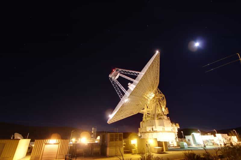
8.2 Satellite communications ground stations
SATCOM stations operate across day-night cycles and still expect stable link budgets. Insertion loss drift matters because it reduces effective radiated power or increases required amplifier margin. Meanwhile isolation and VSWR stability protect high-power amplifiers from mismatches and transient conditions.
8.3 Aerospace payload RF assemblies
Cold start behavior is especially important in aerospace contexts. A circulator that requires “warming up” to meet isolation is a risk. Combined with vibration and mechanical shock requirements, aerospace programs often demand both temperature cycling and mechanical endurance evidence.
9) Industry Outlook: Higher Power Density, Higher Stakes
The trajectory of RF systems is clear: higher integration, higher power density, and more demanding environmental expectations. As systems move to wider bandwidths and higher frequencies, the margin becomes tighter. Small temperature-driven shifts that were once acceptable can become system-level problems—especially when high-power amplifiers operate near compression or when antenna matching is dynamic.
In practical terms, buyers and engineers increasingly ask for:
- Temperature plots (IL, isolation, VSWR vs. temperature) rather than single-point specs.
- Cycle-based qualification evidence, not just “works at cold/hot once.”
- Clear de-rating guidance for CW power under high ambient temperature and real mounting conditions.
- Process-driven consistency that reduces unit-to-unit variability at temperature extremes.
Conclusion
A high-power RF circulator that performs well at 25°C is only halfway proven. The real value appears when performance remains stable and predictable across -55°C to +85°C—the range that harsh environment systems often treat as mandatory.
Temperature affects ferrite properties, magnetic bias, mechanical tolerances, and thermal interfaces. Those effects show up first as isolation drift, VSWR changes, and insertion loss rise—often before any obvious physical damage appears. Strong qualification strategies combine chamber soak and cycling with RF measurement, and for high-power programs, they extend into stress validation and de-rating logic tied to mounting quality and thermal resistance.
For engineers and procurement teams, the most reliable selection approach is to evaluate wide-temperature performance as an envelope: minimum isolation floor, bounded insertion loss drift, controlled VSWR, and documented power behavior across temperature and duty cycle.
10) FAQ
Q1: Why does temperature affect high-power RF circulator isolation more than insertion loss?
Isolation depends strongly on the magnetic bias condition and ferrite behavior at the junction. Temperature-driven changes in magnet flux density and ferrite permeability can shift the operating point. Insertion loss can drift too, but isolation is often the first metric to show meaningful sensitivity.
Q2: Is “-55°C to +85°C” about survival or about RF performance?
It should be about RF performance and reliability. A part can “survive” the temperatures without obvious damage but still suffer performance drift. For harsh environment programs, seek evidence of performance stability after soak and after cycling.
Q3: What is the most common test mistake when validating RF circulator operating temperature?
Insufficient soak time and poor measurement control. Cable/connector behavior at temperature can create false drift if calibration is not managed. Repeatable fixtures, reference checks, and uncertainty bounds help avoid misleading results.
Q4: How should I interpret power ratings across temperature extremes?
Ask for a de-rating curve or guidance tied to ambient temperature and mounting conditions. A “high-power RF circulator” rating is meaningful only when thermal resistance and interface quality are considered. Higher ambient plus poor thermal contact reduces safe continuous power.
Q5: If isolation drops at one edge of the band at high temperature, what should I investigate first?
Start with bias margin and ferrite/magnet temperature behavior. Then check mechanical tolerance stack-up and matching network stability. Also verify the test setup: calibration drift and connector torque differences can mimic band-edge isolation changes.
11) References
- D. M. Pozar, Microwave Engineering, 4th ed., Wiley.
- R. E. Collin, Foundations for Microwave Engineering, 2nd ed., Wiley-IEEE.
- IEEE Transactions on Microwave Theory and Techniques (general background on ferrite components and microwave networks).
- NASA / NOAA public domain imagery used in figures (links in each figure caption).
Recommended Products


.jpg)

Keith Wong
Marketing Director, Chengdu Hertz Electronic Technology Co., Ltd. (Hzbeat)
Keith has over 18 years in the RF components industry, focusing on the intersection of technology, healthcare applications, and global market trends.