Why Do V-Band and W-Band RF Circulators and RF Isolators Use Waveguides?
Learn why V- and W-band RF circulator and RF isolator designs use waveguides for low loss, high isolation, power handling and stable mmWave performance.
 Updated on: Jul 30, 2026
 Author:
Introduction
The continuing development of millimeter-wave radar, satellite communications, high-speed wireless links, security imaging and precision test equipment is increasing demand for reliable V-band and W-band components, especially the RF circulator and RF isolator used to control reflected power.
At these frequencies, the choice of transmission medium has a major effect on insertion loss, power capacity, shielding, bandwidth and measurement accuracy. Although coaxial cables and planar transmission lines remain valuable in many designs, metallic waveguides are often preferred for routing signals and building high-performance passive components.
Why are waveguide components particularly well suited to V-band and W-band systems? The answer lies in their low dielectric loss, favorable power-handling capability, strong electromagnetic shielding and predictable propagation behavior. These advantages are particularly valuable in a waveguide RF circulator or RF isolator, where isolation, insertion loss and port matching directly affect front-end performance.
What Are the V-Band and W-Band?
Under the commonly referenced IEEE radar-frequency designation, V-band covers approximately 40 to 75 GHz, while W-band covers 75 to 110 GHz. Both are part of the millimeter-wave spectrum, where free-space wavelengths are measured in only a few millimeters.
Common waveguide interfaces used around V-band and W-band
| Waveguide | Typical Range | Common Description |
|---|---|---|
| WR-15 | 50–75 GHz | V-band waveguide |
| WR-12 | 60–90 GHz | E-band waveguide; overlaps upper V-band and lower W-band |
| WR-10 | 75–110 GHz | W-band waveguide |
Why Waveguide Components Are Preferred at V-Band and W-Band
1. Lower Transmission Loss in Many Millimeter-Wave Systems
As operating frequency increases, conductor surface resistance rises because of the skin effect. Dielectric losses, surface roughness and radiation from discontinuities can also become increasingly important in coaxial and planar transmission structures.
A hollow metallic waveguide does not require a solid dielectric along its main propagation path. This eliminates most dielectric loss from the transmission medium. A correctly designed and manufactured waveguide can therefore provide comparatively low attenuation, especially when a signal must travel beyond a short chip-level or board-level interconnection.
Waveguides are not lossless. Their actual performance depends on metal conductivity, plating quality, internal surface roughness, waveguide dimensions and flange alignment. Nevertheless, they frequently offer an effective low-loss solution for V-band and W-band signal paths.
2. Greater Power-Handling Capability
Waveguide structures can generally accommodate higher RF power than very small planar transmission lines. Electromagnetic energy is distributed across the waveguide cross-section, reducing the field concentration that can occur around miniature conductors and dielectric interfaces.
The metallic enclosure also provides a useful thermal path. These characteristics make waveguide technology attractive for radar transmitters, power amplifiers, frequency multipliers, signal sources and power-combining systems. The exact power limit still depends on frequency, pressure, pulse duration, flange condition and component geometry.
3. Strong Electromagnetic Shielding
A closed metallic waveguide confines the electromagnetic field within a conductive structure. This helps reduce unwanted radiation and limits the influence of external electromagnetic interference.
Effective shielding is particularly valuable in high-dynamic-range receivers, radar front ends and precision measurement systems, where even small amounts of leakage or coupling can affect sensitivity and measurement uncertainty.
4. High-Q Filters and Resonators
Waveguide cavities can achieve a high unloaded quality factor because they avoid many of the dielectric and radiation losses associated with planar structures. This makes waveguide technology well suited to narrowband filters, multiplexers and resonant components.
A higher Q can help designers obtain lower passband insertion loss, sharper frequency selectivity and stronger out-of-band rejection. These characteristics are important in communication and radar systems that must separate closely spaced channels or reject unwanted signals.
5. Predictable Propagation Modes
A rectangular waveguide supports electromagnetic modes only above their respective cutoff frequencies. Its dimensions can be selected so that the dominant TE10 mode propagates across the intended operating band while unwanted higher-order modes remain below cutoff or outside the normal operating range.
This controlled mode behavior gives engineers a well-defined transmission environment and supports repeatable filters, couplers, attenuators, antennas and calibration standards.
6. Standardized Interfaces for Testing and Integration
Standard waveguide sizes and precision flanges make it possible to connect components from signal generators, frequency extenders, mixers, antennas and vector network analyzer systems.
For example, commercial WR-15 systems commonly cover 50 to 75 GHz, while WR-10 test equipment covers 75 to 110 GHz. These established interfaces simplify component replacement, system integration and traceable RF calibration.
Why RF Circulator and RF Isolator Performance Matters at V-Band and W-Band
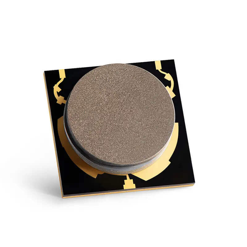
An RF circulator is a multi-port non-reciprocal device that routes RF energy sequentially from one port to the next. In a typical three-port design, energy entering port 1 travels to port 2, energy entering port 2 travels to port 3, and energy entering port 3 returns to port 1. This directional routing allows a transmitter and receiver to share an antenna, separates incident and reflected signals, and protects sensitive stages from reverse energy.
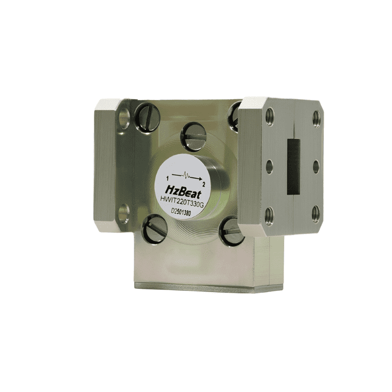
An RF isolator is commonly created by terminating one port of an RF circulator with a matched load. The resulting two-port component passes energy with low loss in the forward direction while absorbing a substantial portion of reverse power. In V-band and W-band systems, an RF isolator can reduce the effect of antenna mismatch, stabilize a millimeter-wave amplifier or frequency multiplier, and protect a source from load-pull caused by downstream reflections.
At millimeter-wave frequencies, even a small discontinuity can create a meaningful reflection. A waveguide RF circulator and waveguide RF isolator therefore require precise flange geometry, a carefully designed ferrite junction and controlled magnetic bias. When these features are optimized together, the device can deliver low forward insertion loss, useful reverse isolation and stable port matching across its specified bandwidth.
Waveguide RF Circulator
A V-band RF circulator or W-band RF circulator is often installed in a radar, transceiver or measurement front end. Its waveguide ports confine the electromagnetic field and connect directly to filters, horns, couplers and frequency-extender modules. Key specifications include insertion loss, isolation, return loss, operating bandwidth, power rating and the direction of circulation.
Waveguide RF Isolator
A V-band RF isolator or W-band RF isolator is generally selected when the system needs one-way protection rather than three-port signal routing. Its internal termination must safely absorb reflected energy, so thermal design and reverse-power rating are important alongside isolation. In sensitive test systems, the RF isolator also reduces the influence of changing load impedance on source output power and phase.
Common V-Band and W-Band Waveguide Components
A wide range of passive and active millimeter-wave devices can use waveguide interfaces, including:
- Waveguide filters and diplexers
- Directional couplers
- Power dividers and combiners
- Fixed and variable attenuators
- Waveguide RF circulator and RF isolator components
- Waveguide switches
- Horn antennas and antenna feeds
- Frequency multipliers and mixers
- Coaxial-to-waveguide and microstrip-to-waveguide transitions
- Calibration kits, loads, shorts and precision waveguide sections
These components are widely used in automotive and aerospace radar, satellite payloads, remote sensing, radio astronomy, material characterization, security screening and millimeter-wave test laboratories.
Limitations of V-Band and W-Band Waveguides
Waveguide components are not automatically the best solution for every millimeter-wave design. Conventional metal waveguides can be larger, heavier and more expensive than planar alternatives. They may also be more difficult to integrate directly with semiconductor devices.
Manufacturing accuracy becomes especially important at W-band. Dimensional errors, internal surface roughness, flange misalignment and assembly gaps can increase insertion loss, degrade return loss or excite unwanted modes.
For compact and high-volume products, engineers may instead use substrate-integrated waveguide, micro-machined waveguide, silicon-based structures or carefully designed transitions between planar circuits and metal waveguides. The final choice should be based on loss, bandwidth, size, weight, power, production volume, integration method and cost.
Waveguide, Coaxial or Planar Transmission Line?
The correct transmission technology depends on where the signal travels and which performance parameter dominates the design. A planar line is usually the natural choice for short interconnections between semiconductor devices on the same substrate. A precision coaxial interface can provide convenient broadband access to a module. A waveguide becomes especially attractive when the signal must pass through a low-loss front end, filter network, antenna feed or calibrated test path.
At V-band and W-band, this decision is rarely based on nominal attenuation alone. Engineers must also evaluate transition loss, mismatch, assembly repeatability, connector durability, thermal behavior and the possibility of unwanted resonances. A low-loss waveguide section can still deliver poor system performance if its flange is misaligned or if the transition from the active circuit is badly matched.
Practical comparison of millimeter-wave transmission technologies
| Technology | Main Strengths | Typical Limitations | Suitable Uses |
|---|---|---|---|
| Metal waveguide | Low dielectric loss, strong shielding, high Q and good power handling | Mechanical size, precision machining cost and tighter assembly tolerances | Filters, antenna feeds, radar front ends and calibrated test paths |
| Precision coaxial line | Broadband connection, flexible routing and familiar measurement interfaces | Rising conductor loss and increasingly delicate connectors at high frequency | Instrument interconnects, adapters and broadband module access |
| Microstrip or grounded coplanar waveguide | Compact, inexpensive and compatible with semiconductor integration | Dielectric loss, radiation, dispersion and sensitivity to fabrication details | Short on-board routes, MMIC transitions and compact integrated modules |
| Substrate-integrated waveguide | Combines planar fabrication with waveguide-like field confinement | Still affected by substrate loss and via or fabrication tolerances | Integrated filters, antennas and compact front-end assemblies |
Key Engineering Considerations for V-Band and W-Band Waveguides
Surface Finish and Conductivity
At millimeter-wave frequencies, current is concentrated in a very shallow region near the metal surface. Surface roughness that appears insignificant at lower frequencies can therefore increase effective resistance. Base material, plating thickness, oxidation resistance and internal machining quality should all be considered when specifying a low-loss component.
Dimensional Accuracy
The broad-wall and narrow-wall dimensions determine cutoff frequencies and modal behavior. Small deviations can shift the response of a resonator or filter, while rounded internal corners and tool marks can alter the intended electromagnetic geometry. This is why W-band hardware often requires precision CNC machining, electroforming, micromachining or carefully controlled split-block construction.
Flange Alignment and Contact
A flange joint is part of the RF circuit, not merely a mechanical connection. Lateral offset, angular error, contamination or a visible gap can create mismatch and leakage. Precision alignment pins, clean mating faces and controlled screw torque help produce repeatable measurements and reduce uncertainty.
Mode Control
Bends, steps, tuning screws and transitions must be designed to avoid exciting higher-order or trapped modes. These unwanted fields can create narrow resonances, unexpected insertion-loss peaks or unstable measurement results. Full-wave electromagnetic simulation is therefore commonly combined with vector network analyzer verification.
Thermal and Power Conditions
Average power, peak pulse power and environmental pressure affect breakdown and heating differently. A component intended for a laboratory receiver may not be suitable for a pulsed radar transmitter. Designers should examine electric-field concentration, thermal paths, ferrite or dielectric limits and the power rating of every transition in the chain.
How to Select a V-Band or W-Band Waveguide Component
A useful specification process starts with the complete operating range rather than only the center frequency. The selected waveguide must support the required band while maintaining acceptable insertion loss, return loss and mode purity. For example, a system operating from 75 to 110 GHz will normally use WR-10, while equipment operating from 50 to 75 GHz commonly uses WR-15.
Buyers and system engineers should then compare the following parameters:
- Frequency range: Confirm both the nominal waveguide band and the guaranteed component bandwidth.
- Insertion loss: Evaluate the maximum specified value across frequency and temperature, not only a typical center-band result.
- Return loss or VSWR: Good matching reduces reflected power and measurement uncertainty.
- Isolation and directivity: These values are particularly important for isolators, circulators and directional couplers.
- Power rating: Check continuous-wave and peak ratings along with duty cycle and operating pressure.
- Flange type: Verify mechanical compatibility, alignment-pin arrangement and interface standard.
- Environmental requirements: Consider temperature, vibration, humidity, vacuum compatibility and corrosion protection.
- Calibration and traceability: Precision test applications may require measured S-parameters and traceability to a national metrology institute.
Because measurement fixtures become part of the signal path at these frequencies, it is also important to define the calibration reference plane. Adapters, bends and transitions located after the calibration plane contribute directly to the measured loss and mismatch.
Applications Driving V-Band and W-Band Demand
V-band spectrum is attractive for high-capacity short-range links, experimental communications and specialized radar systems. W-band supports high-resolution radar, atmospheric and remote-sensing instruments, security imaging, radio astronomy and advanced material measurements. The short wavelength enables compact high-gain antennas and fine spatial resolution, while the available bandwidth supports detailed ranging and high data rates.
In test laboratories, waveguide frequency extenders allow vector network analyzers and signal sources to characterize devices well beyond the direct coaxial range of the base instrument. Standard waveguide interfaces make it possible to assemble measurement chains from multipliers, mixers, attenuators, couplers, antennas and calibration standards.
Continued progress in additive manufacturing, silicon micromachining and low-loss surface treatments may reduce the size and cost of future waveguide assemblies. Hybrid modules that combine MMICs, planar transitions and precision metal waveguides are also likely to remain important because they balance integration density with low-loss external signal routing.
Conclusion
V-band and W-band systems frequently use waveguide components because waveguides provide a combination of low dielectric loss, high power capacity, strong shielding, high-Q performance and controlled propagation modes.
Standard interfaces such as WR-15 and WR-10 also make waveguide components convenient for millimeter-wave testing and modular system integration. Coaxial and planar technologies remain important, particularly for compact or highly integrated products, but waveguide technology continues to be a leading choice when RF performance and measurement repeatability are the primary requirements.
As millimeter-wave radar, satellite communications, imaging and next-generation wireless research continue to develop, demand for precision V-band and W-band waveguide filters, couplers, antennas, adapters and test components is expected to remain strong.
Frequently Asked Questions
What frequency ranges do the V-band and W-band cover?
Under the commonly referenced IEEE radar-band designation, V-band covers 40 to 75 GHz and W-band covers 75 to 110 GHz. Commercial WR-15 products are normally described as V-band waveguide components and typically operate from 50 to 75 GHz.
Why do waveguides perform well at millimeter-wave frequencies?
A hollow metallic waveguide carries electromagnetic energy without relying on a solid dielectric along the main transmission path. Properly designed waveguides can therefore provide low dielectric loss, strong shielding and predictable mode behavior.
Which waveguide sizes are used for V-band and W-band?
WR-15 is commonly used from 50 to 75 GHz, while WR-10 is commonly used from 75 to 110 GHz. WR-12, with a typical range of 60 to 90 GHz, overlaps parts of the upper V-band and lower W-band.
Are waveguide components always better than coaxial components?
No. Waveguides are attractive when loss, isolation, power handling or high-Q performance is critical. Coaxial solutions may offer greater flexibility and easier connection, especially when wide frequency coverage or compact cable routing is required.
Can microstrip circuits be used at V-band and W-band?
Yes. Microstrip and other planar technologies are widely used in compact integrated modules. However, substrate loss, conductor roughness, radiation and fabrication tolerances must be carefully controlled at millimeter-wave frequencies.
What applications use V-band and W-band waveguide components?
Common applications include millimeter-wave radar, satellite communications, remote sensing, security imaging, radio astronomy, material testing and vector network analyzer measurement systems.
What is the difference between an RF circulator and an RF isolator?
An RF circulator is normally a three-port non-reciprocal device that routes energy sequentially between ports. An RF isolator is commonly formed by terminating one circulator port, creating a two-port device that passes forward energy while absorbing reverse power.
Why use a waveguide RF circulator at V-band or W-band?
A waveguide RF circulator combines non-reciprocal signal routing with the low dielectric loss, shielding and power-handling benefits of a metallic waveguide. It can separate transmit and receive paths or route reflected energy away from a sensitive source.
How do I select a V-band or W-band RF isolator?
Confirm the required waveguide size and frequency range, then compare insertion loss, isolation, return loss, forward and reverse power ratings, bandwidth, flange type and environmental specifications. The RF isolator should be evaluated across the full operating range rather than only at center frequency.
References
- IEEE Standards Association, IEEE 521-2026: Standard Letter Designations for Radar-Frequency Bands. IEEE standard page.
- IEEE Technology Navigator, Millimeter Wavebands. Frequency-band overview.
- Keysight Technologies, Waveguide Power Sensors. Waveguide bands and applications.
- Keysight Technologies, W11645A WR-10 Verification Kit. WR-10 specifications.
- National Institute of Standards and Technology, Testing Dielectric Slab Mode Excitation, Non-Rectangular Conductor Profiles and Edge Roughness as Sources of Additional Loss in mmWave Transmission Lines, 2023. NIST publication.
- David M. Pozar, Microwave Engineering, 4th Edition, John Wiley & Sons, 2011.
Recommended Products
.jpg)
 Article Tags
Keith Wong
Marketing Director, Chengdu Hertz Electronic Technology Co., Ltd. (Hzbeat)
Keith has over 18 years in the RF components industry, focusing on the intersection of technology, healthcare applications, and global market trends.