Can an RF Circulator Replace a Duplexer? Understanding When It Works — and When It Doesn't.
Updated on:
Keywords: rf circulator replace duplexer, tdd vs fdd duplexing, hybrid duplexing network design, group delay ripple evm, circulator time blanking method
No repetition, no fluff — a boundary-focused guide: TDD versus FDD, leakage math that drives RX desense, failure modes you must respect, and a lab test plan to prove it.
Table of Contents
- Short Answer (TL;DR)
- Direction vs Frequency Separation — One Graphic to Rule It
- TDD Success Case — How a Circulator Can Stand In
- FDD Failure Case — Why a Duplexer Is Non‑negotiable
- The Math of Leakage‑Driven RX Desense
- Lab Validation Plan (Pass/Fail Criteria)
- Hybrid Alternatives (Circulator + Filters/Switches)
- Common Pitfalls & Correctives
- References
Short Answer (TL;DR)
Yes, for TDD and same‑frequency links; No, for FDD and simultaneous TX/RX. A circulator provides directional isolation (~20–25 dB) and works when TX and RX do not overlap in time. A duplexer provides steep frequency separation and high TX↔RX isolation (>60 dB) and is mandatory when they do.
If you need a general selection guide (not the boundary problem), see our companion article.
Direction vs Frequency Separation — One Graphic to Rule It
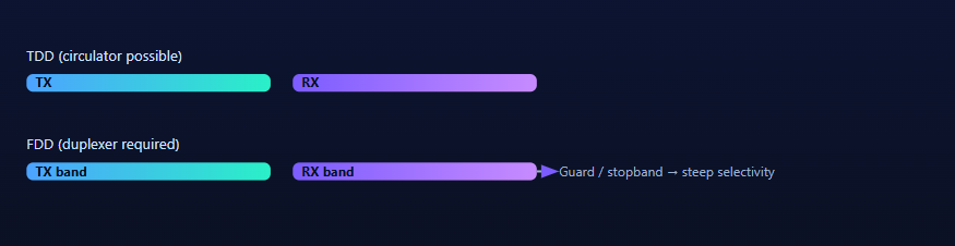
TDD Success Case — How a Circulator Can Stand In
Case: X‑band pulsed radar TR module
- TX pulse width 20 µs, PRF 1 kHz; RX gate opens 15 µs after TX blanking.
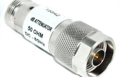
- Circulator isolation 22 dB; forward IL 0.6 dB; VSWR ≤ 1.25:1.
- Receiver front‑end muted during TX; recovery in 5 µs, within guard time.
Result:
With timing discipline and moderate isolation, the circulator meets range‑bin requirements without a duplexer. Add a PA‑side isolator for mismatch events.
FDD Failure Case — Why a Duplexer Is Non‑negotiable
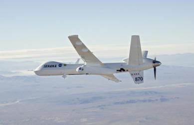
Case: Ku‑band FDD ground station (simultaneous TX/RX)
- TX EIRP high; RX requires sensitivity near thermal noise floor.
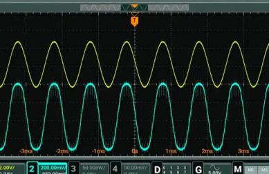
- Using only a circulator, TX→RX leakage elevates the RX noise floor by ~8 dB.
- EVM/ACLR compliance fails; adjacent‑band emissions exceed mask.
Takeaway:
Without steep filter skirts and >60 dB isolation, a circulator cannot protect the RX chain in FDD. A cavity/ceramic duplexer is mandatory.
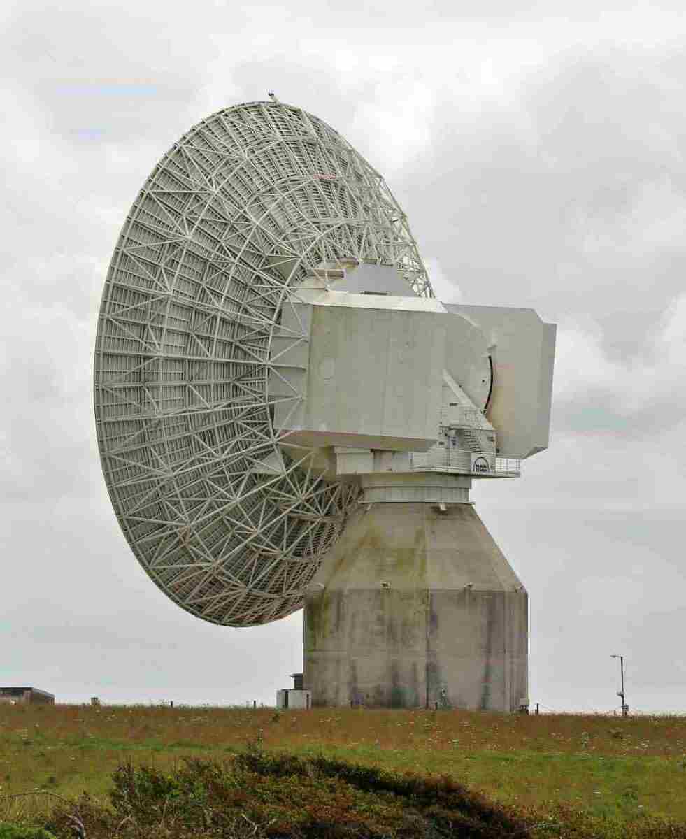
Simultaneous satellite links demand high TX↔RX isolation and strict masks. Photo © Nilfanion, CC BY-SA 3.0, via Wikimedia Commons.
The Math of Leakage‑Driven RX Desense
Estimate required TX→RX isolation from the link budget and receiver sensitivity:
Rule of thumb
Required Isolation (dB) ≥ PTX + Gpath − (NF + SNRreq + Margin) − Psens
Where Gpath is the unintended coupling from TX chain into RX chain (through antenna/structure/cables), Psens is the receiver sensitivity, and Margin accounts for temperature, aging, and manufacturing spread.
Example thresholds
- Well‑designed FDD base stations often need >60–70 dB TX↔RX isolation to keep leakage below the RX noise contribution.
- TDD radar with aggressive blanking may pass with ~20–25 dB circulator isolation (plus PA‑side isolator).
For modulated links, control group delay ripple and amplitude ripple; both drive EVM beyond budget even if isolation math looks OK.
Lab Validation Plan (Pass/Fail Criteria)
Bench setup
RF source → PA → DUT path (circulator / duplexer / hybrid) → directional coupler → antenna/load; RX chain monitored via spectrum analyzer and VNA for S‑parameters; optionally a vector signal analyzer for EVM/ACLR.
| Test | Target / Pass | Notes |
|---|---|---|
| TX→RX leakage (dB) | FDD: ≥60–70; TDD: ~20–25 + blanking | Over temperature/frequency |
| Group delay ripple | ≤ specified (e.g., ≤2–5 ns) | Impacts EVM |
| EVM/ACLR | Per 3GPP/mission spec | Use realistic waveforms |
| VSWR / match | <1.25:1 preferred | Watch temperature drift |
| Hot‑switch & mismatch | No damage, stable PA | Monitor isolator load temperature |
Hybrid Alternatives (Circulator + Filters/Switches)
- Circulator + Band‑pass/Notch filters: Adds selectivity to directionality; effective where space permits.
- Circulator + T/R switch + RX blanking: Classic TDD radar method; timing discipline is key.
- PA‑side Isolator: Mandatory for mismatch/hot‑switch tolerance; design thermal path for the termination.
See: Waveguide Isolators · SMT Isolators
Common Pitfalls & Correctives
- Confusing direction with selectivity: A circulator controls direction; a duplexer controls frequency.
- Ignoring thermal design: The termination on isolators must survive worst‑case VSWR events.
- Evaluating at room temp only: Re‑measure isolation/IL/VSWR over temp and after vibration.
- Waveform mismatch: Validate with real modulations, not just CW; check EVM/ACLR.
References
- R. E. Collin, Foundations for Microwave Engineering, 2nd ed., McGraw‑Hill.
- IEEE MTT tutorials and classic papers on ferrite nonreciprocal devices (circulators/isolators).
- MDPI Electronics/Sensors special issues on ferrite circulators and isolators (open access case studies).
- NASA Technical Reports (microwave front‑ends with ferrite components), open literature.
- 3GPP EVM/ACLR specifications guiding RX desense and TX leakage budgets in FDD systems.
Need boundary guidance for your project?
Tell us your frequency plan (TDD/FDD), power, and masks — we’ll propose a circulator/isolator set or a hybrid path that passes the lab.
Relateds
About the Author

HzBeat Editorial Content Team
Marketing Director, Chengdu Hertz Electronic Technology Co., Ltd. (Hzbeat)
Keith has over 18 years in the RF components industry, focusing on the intersection of technology, healthcare applications, and global market trends.