RF Isolator vs. Circulator: A Quick Guide
Updated on:
Keywords: RF isolator, RF circulator,insertion loss,isolation,power handling,Isolators vs Circulators in RF System
Isolators and circulators are non‑reciprocal devices based on ferrite materials, playing a critical role in RF systems by protecting key components (such as power amplifiers) and enabling directional signal transmission. A thorough understanding of their operating principles, performance parameters (primarily characterized by S-parameters), and applicable scenarios is vital for system design.
Operating Principles and Performance Parameters of Isolators
Physical Basis & Operating Mechanism
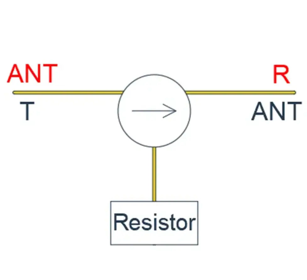
Isolators leverage the gyromagnetic effect exhibited by ferrite materials under an external DC bias magnetic field. When a microwave signal travels in the forward (low‑loss) direction, the ferrite absorbs almost none of the energy; when it travels in the reverse (high‑loss) direction, the ferrite strongly absorbs the signal and converts it into heat. This non‑reciprocity is the isolator’s defining feature.
Key S-Parameters & Performance Metrics
- Insertion Loss (S₂₁): Forward transmission loss; ideally near 0 dB, but typically 0.2 – 1.0 dB. Low insertion loss is crucial for system efficiency.
- Isolation (S₁₂): Reverse transmission loss, the core metric for isolation performance; usually 20 – 40 dB or higher. High isolation effectively blocks reflected signals from damaging the source (e.g., the power amplifier).
- Input/Output Return Loss (S₁₁, S₂₂): Measures port‑matching quality; typically required to be better than 15 – 20 dB to ensure efficient signal ingress and egress, reducing system reflections.
- Bandwidth: The frequency range over which the above metrics are satisfied.
- Power Handling: The maximum continuous-wave (CW) or peak power the device can safely withstand.
Operating Principles and Performance Parameters of Circulators
Physical Basis & Operating Mechanism
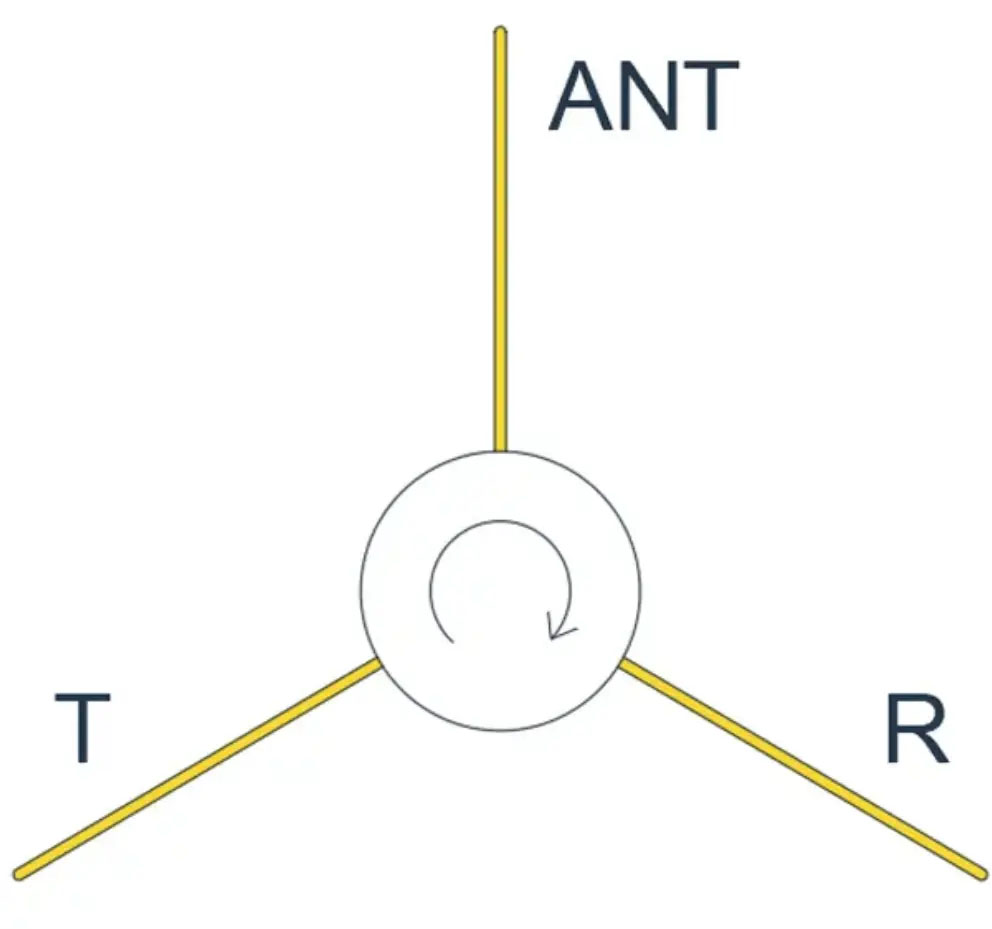
Circulators are typically three‑port (or multi-port) devices also based on the ferrite gyromagnetic effect combined with specific cavity structures (such as Y-junctions or stripline designs). Signals "circulate" among the ports in a fixed order. For example, in an ideal three-port circulator: a signal entering Port 1 is transmitted only to Port 2; a signal entering Port 2 only to Port 3; and a signal entering Port 3 only to Port 1.
Key S-Parameters & Performance Metrics
- Insertion Loss(S₂₁, S₃₂, S₁₃): Forward transmission loss between adjacent ports, depending on the circulation direction; performance requirements mirror those of isolators.
- Isolation(S₁₂, S₂₃, S₃₁): Reverse transmission loss (i.e., loss for signals attempting to travel against the circulation direction); this is the key metric for circulator performance and must be high.
- Return Loss(S₁₁, S₂₂, S₃₃): Port-matching performance at each port.
- Circulation Direction: The fixed sequence of signal flow (clockwise or counterclockwise), determined by the direction of the bias magnetic field.
- Bandwidth: The frequency range over which the above specifications are met.
- Power Handling: The maximum continuous-wave (CW) or peak power the device can safely withstand.
| Feature | Circulator | Isolator |
|---|---|---|
| Core Function | Signal circulation routing | Unidirectional transmission; reverse isolation |
| Typical Ports | 3 ports or 4 ports | 2 ports |
| Signal Flow | Port 1 → Port 2 → Port 3 → Port 1 (fixed loop) | Port 1 → Port 2 (forward pass) Port 2 → Port 1 (reverse absorption) |
| Reverse Handling | Blocks and reflects back to the preceding port | Absorbs and dissipates as heat |
| Typical Applications |
|
|
| Performance Parameter Focus | Emphasis on high reverse isolation and low forward insertion loss | Emphasis on low forward insertion loss, high reverse isolation, and good return loss at each port to ensure low loss and high isolation along the RF path |
HzBeat Professional Summary: RF Isolators & Circulators
HZBEAT delivers a concise yet authoritative overview of two pivotal ferrite-based non-reciprocal RF devices: isolators and circulators. As experts at Chengdu Hzbeat Electronic Technology Co., Ltd., we ensure unidirectional signal protection and flexible multi-port signal routing solutions for modern RF systems.
Isolators: Unidirectional Protection via Gyromagnetic Effect
RF isolators exploit the ferrite gyromagnetic effect under DC bias to enable true unidirectional transmission-minimizing forward-path insertion loss while strongly attenuating reverse-path signals to safeguard power amplifiers. Key metrics include insertion loss, isolation, and return loss, all critical for high‑efficiency RF chain design.
Circulators: Flexible Multi-Port Signal Routing
RF circulators use specialized cavity or stripline structures to cyclically route signals among three (or more) ports in a fixed sequence (e.g., Port 1→Port 2→Port 3→Port 1). With low insertion loss and high reverse isolation, circulators support versatile applications from radar T/R modules to automated test systems.
Performance Metrics & Applications
This summary examines critical S-parameter performance—insertion loss, isolation, and return loss—as well as bandwidth and power-handling capabilities. We compare typical use cases such as radar T/R modules, base-station duplexers, and automated test systems to guide RF engineers in selecting and integrating optimal components.
With HzBeat's professional framework, achieve efficient, reliable directional signal routing across diverse RF scenarios and ensure robust system performance.
Customization & Quality Assurance
At HZBEAT, we specialize in customized R&D services and agile small-batch prototyping for RF isolators and RF circulators across Microstrip, Coaxial, and Waveguide product lines. All devices are manufactured on ISO 9001-certified production lines and undergo rigorous RoHS-compliant testing, guaranteeing low insertion loss, high isolation, and robust power-handling performance. Precision machining and optimized ferrite magnetic bias ensure tight S-parameter tolerances and reliable operation under demanding microwave and millimeter-wave conditions.
Conclusion & Next Steps
Partnering with HZBEAT gives you access to cutting-edge, ferrite-based RF isolators and circulators backed by expert design, certified manufacturing, and global technical support. To explore detailed S-parameter specifications, bandwidth, and power-handling datasheets, please visit the HZBEAT Product Center and download our comprehensive product manuals. Enhance your RF system's reliability and performance with HZBEAT's professional solutions today.
For more detailed information on our RF isolators and circulators, visit the https://www.hzbeat.com/working-principle/
For more detailed information, please visit the HzBeat Product Center and download the relevant product manuals.
Relateds


About the Author

HzBeat Editorial Content Team
Sara is a Brand Specialist at Hzbeat, focusing on RF & microwave industry communications. She transforms complex technologies into accessible insights, helping global readers understand the value of circulators, isolators, and other key components.