How to Choose the Right RF Isolator for Modern Microwave Systems
Updated on:
Keywords: How to Choose the Right RF Isolator, RF isolator selection guide, RF isolator, microwave isolator, drop-in isolator, microstrip isolator, coaxial isolator, waveguide isolator

In modern RF and microwave systems, the isolator is a small component with a very big responsibility. It protects power amplifiers from high VSWR, stabilizes gain blocks, and keeps high-value systems from quietly degrading or suddenly failing. A poorly chosen isolator can lead to oscillations, burned-out amplifiers, unstable measurement results, or unexpected downtime. A well-matched isolator, on the other hand, helps your RF chain stay clean, stable, and reliable over years of operation.
This article walks through how to select an RF isolator step by step—from basic parameters such as frequency and power, to practical engineering issues like integration, thermal design, and reliability in the field. For engineers who need production-ready components, suppliers like HzBeat provide RF circulators and isolators across microstrip, drop-in, coaxial, and waveguide formats to cover bands from MHz to mmWave.
1. What Is an RF Isolator and Why It Matters
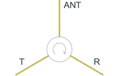
An RF isolator is a two-port, non-reciprocal device that allows RF energy to pass in one direction (port 1 → port 2) while strongly attenuating energy in the reverse direction (port 2 → port 1). In practice, it is used to:
- Protect power amplifiers from reflected power caused by high VSWR at the load
- Improve stability by preventing unwanted feedback along the RF chain
- Decouple high-gain or sensitive stages in complex front-ends
- Improve measurement accuracy in RF and microwave test setups
In high-power radar, SatCom, 5G/6G infrastructure, medical imaging, and precision test systems, the isolator acts as a silent safety valve. Choosing the wrong device means accepting risk at the system level; choosing the right one means your RF path remains predictable, robust, and easier to maintain.
2. Start with the System: Key Application Questions
Before you open any datasheet, start with your system requirements. Clear answers to the questions below will narrow down the isolator type and performance class you need:
- Operating frequency band: Narrowband or truly broadband? Single radar band, or multi-band architecture?
- Power level: What are the average and peak (pulsed) power levels, and what is the duty cycle?
- VSWR environment: How bad can the load mismatch be under fault or normal conditions?
- Dynamic range and noise: How sensitive is your receiver or measurement chain to added loss?
- Integration constraints: PCB-based front-end, hybrid module, coaxial rack system, or waveguide line?
- Environment: Indoor lab, outdoor telecom, airborne platform, or space / vacuum?
The answers determine which technology (microstrip, drop-in, coaxial, or waveguide) is suitable, and what performance envelope—loss, isolation, power, and temperature—the isolator must meet.
3. Technology & Package Types
RF isolators are implemented in several physical formats, each optimized for different integration styles and power levels.
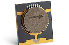
3.1 Microstrip Isolators
Microstrip isolators are planar structures on a dielectric substrate, using ferrite material and permanent magnets to realize non-reciprocal behavior. They are ideal for:
- PCB-level integration in compact RF modules
- Low-profile, lightweight front-ends for 5G, radar, and SatCom
- Systems where miniaturization and high-density layouts are critical
Microstrip solutions are well suited when you are already routing microstrip lines and want to avoid additional connectors. Careful attention to substrate choice, loss tangent, and grounding is required to maintain low insertion loss and predictable bandwidth.
3.2 Drop-in Isolators
Drop-in isolators are compact blocks designed to be mounted in a milled cavity or on a metallic carrier, with RF pins or tabs for connection. They are a popular choice in T/R modules and compact RF assemblies.
- Good balance between footprint, power handling, and broadband performance
- Robust mechanical mounting and reliable grounding
- Flexible to customize for specific bands or bandwidths
For designers needing production-ready solutions, HzBeat offers drop-in isolators up to 40 GHz covering S, C, X, Ku and other key bands, with options for typical, broadband, and high-power variants.
3.3 Coaxial Isolators
Coaxial isolators are housed in connectorized packages (e.g., SMA, N-type) that can be inserted directly into coaxial lines. They are widely used in:
- Test and measurement setups and RF benches
- Repeater systems, base stations, and instrumentation racks
- Temporary or reconfigurable system testbeds
The plug-and-play nature of coaxial isolators makes them ideal for system prototyping and lab environments, though they generally occupy more volume than microstrip or drop-in components.
3.4 Waveguide Isolators
Waveguide isolators are integrated directly into a waveguide body with standard flanges (WR series etc.). They are typically used at higher frequencies and power levels, including Ku, Ka, V, W and D band systems.
- Excellent power handling for high-power radar and uplink chains
- Very low insertion loss at microwave and millimeter-wave frequencies
- Well-suited for critical SatCom and radar front-ends where efficiency matters
Mechanical alignment, flange quality, and environmental sealing all play a role in keeping waveguide isolator performance stable over time.
4. Core Electrical Parameters You Must Check
A good port match reduces reflections and standing waves in the system. Check VSWR (or return loss) at both ports. Values of ≤ 1.25–1.35:1 across the band are common for high-quality isolators.
Poor VSWR at the isolator input can create reflections even before the device has a chance to protect downstream components, degrading linearity and potentially interacting with other matching networks.
4.5 Power Handling (Average and Peak)
Power handling is where many designs quietly fail. Consider:
- Average RF power from the amplifier
- Worst-case reflected power under high VSWR, including fault conditions
- Peak or pulsed power, duty cycle, and crest factor
The isolator and its internal load must be able to dissipate this power with margin. Operating at or near the rated limit leaves little room for temperature variation, component aging, or unexpected load changes. For radar and pulsed systems, always check both average and peak power ratings.
5. Environmental and Reliability Considerations
Real systems seldom operate at room temperature on a quiet lab bench. Temperature extremes, vibration, humidity, and altitude all influence isolator performance and lifetime.
5.1 Operating Temperature
Ferrite properties and magnet bias change with temperature, affecting isolation, insertion loss, and match. Confirm that:
- The isolator is rated for your full operating and storage temperature range
- Thermal simulations or measurements reflect realistic ambient conditions inside enclosures
- The internal termination can dissipate heat without drifting or failing over time
5.2 Mechanical Robustness
In airborne, naval, or vehicular platforms, vibration and mechanical shock can stress solder joints, connectors, and ferrite structures. For such applications, look for:
- Qualification data against relevant standards (e.g., MIL-STD-810) where applicable
- Mechanically secure mounting for drop-in and waveguide designs
- Strain relief for coaxial cables to avoid overloading connectors
5.3 Lifetime and Stability
Isolators are passive devices with long expected lifetimes, but long-term factors include:
- Magnet bias drift over many thermal cycles
- Aging of resistive loads operated near their power limits
- Environmental effects such as corrosion or contamination in harsh environments
For mission-critical systems, ask your supplier for long-term stability and life-test data, and specify conservative design margins where possible.
6. Integration: How the Isolator Fits into Your RF Chain
Even the best isolator can underperform if it is poorly integrated into the RF layout. Good implementation avoids unnecessary mismatch, parasitics, and overheating.
6.1 Microstrip and Drop-in Integration
For microstrip and drop-in devices:
- Maintain controlled-impedance transitions between PCB traces and RF pads or tabs
- Use solid ground reference planes and dense via fences around the device
- Keep noisy digital or power traces away from the ferrite region to minimize coupling
6.2 Coaxial and Waveguide Interfaces
For connectorized and waveguide isolators:
- Follow recommended torque values and connector-handling practices
- Use high-quality adapters sparingly; every extra adapter adds loss and mismatch
- Ensure waveguide flanges are properly aligned and sealed to maintain performance
6.3 System-Level Placement
Place the isolator as close as practical to the component you want to protect, typically the power amplifier. Avoid long, mismatched lines between the amplifier and isolator, or you risk reintroducing standing waves that defeat the point of the device.
7. Noise, Linearity, and System Performance
Isolators are passive, but they still influence system noise and linearity.
- In receive chains, any loss before the first LNA directly worsens noise figure.
- In transmit paths, insufficient headroom to the isolator’s P1dB and IP3 can introduce distortion.
- High-order products in nonlinear regimes can heat terminations and affect long-term reliability.
In low-noise receivers, isolators are often placed after the LNA or in later stages where added loss is less critical but stability benefits remain. In power transmitters, confirm that isolator linearity and power ratings exceed the maximum expected drive conditions with comfortable safety margins.
8. Supplier, Customization, and Documentation
Selecting the right supplier is almost as important as selecting the right part number. A strong partner can support you through prototype, qualification, and volume production.
When evaluating suppliers, consider whether they can:
- Provide broadband S-parameter files across your full operating band
- Offer microstrip, drop-in, coaxial, and waveguide options within a consistent technology platform
- Customize frequency bands, connector types, or mechanical footprints for your platform
- Support long-term delivery, quality control, and engineering feedback
For OEM and system integrators, working with a vendor that covers everything from 20 MHz-class front-ends to millimeter-wave links simplifies future platform evolution and reduces supplier complexity.
9. Practical RF Isolator Selection Checklist
As you compare candidate parts, the checklist below can serve as a concise summary of what to confirm before freezing your design.
- Frequency band: Does the rated band fully cover your operating band with margin?
- Technology and package: Microstrip, drop-in, coaxial, or waveguide—does it match your architecture?
- Insertion loss: Is forward loss acceptable for your link budget and noise requirements?
- Isolation: Is reverse isolation high enough to protect the PA under worst-case VSWR?
- VSWR: Are both ports well matched across the band?
- Power handling: Are average and peak ratings sufficient with realistic margins?
- Thermal behavior: Can the assembly remove heat under maximum ambient and duty cycle?
- Environment: Do temperature, vibration, and humidity ratings meet system requirements?
- Integration: Are mechanical footprint, connectors, and PCB layout straightforward?
- Supplier support: Are documentation, customization, and long-term supply robust?
10. FAQ: Common Questions About Choosing RF Isolators
Q1. How much isolation is “enough” for a power amplifier output?
For many microwave PAs, a minimum of 18–20 dB isolation across the operating band is considered the baseline. For highly mismatched loads, tunable antennas, or critical radar and SatCom systems, engineers often target 23–30 dB or more to maintain stability and protect sensitive devices. The higher the possible reflected power, the more isolation you should budget.
Q2. Should I prioritize lower insertion loss or higher isolation?
It depends on the function of the stage. In receive paths close to the LNA, insertion loss directly impacts noise figure, so minimizing loss is usually the priority. In high-power transmit paths, protecting the PA and stabilizing matching is often more important, so higher isolation can take priority over a small reduction in insertion loss. In many designs, a balanced compromise is achievable.
Q3. How do I estimate the power the internal termination must dissipate?
Start from the maximum forward power of your amplifier and the worst-case VSWR at the load. Under full reflection (|Γ| ≈ 1), nearly all the power can return toward the amplifier. The isolator directs that reverse power into its internal load. Multiply by your duty cycle for pulsed systems and apply a safety margin; the termination’s rating should exceed this worst-case average and peak dissipation.
Q4. When should I consider a custom RF isolator instead of a standard part?
If your application requires unusual bandwidth, non-standard connectors, very tight size constraints, or specific environmental qualification (e.g., aerospace or defense standards), a custom or semi-custom solution is often the best path. Many suppliers can adapt existing platforms to your frequency band and power class with relatively short lead times, while maintaining predictable performance and manufacturability.
11. Conclusion
Choosing the right RF isolator for modern microwave systems is fundamentally a system-level decision. Start from your frequency band and architecture, then systematically evaluate technology, electrical performance, power handling, environment, integration, and supplier capabilities.
When these factors are aligned, the isolator becomes what it is meant to be: a quiet guardian in the RF chain, protecting amplifiers, stabilizing matching, and allowing your radar, SatCom, communication, or test system to deliver reliable performance year after year.
Relateds

About the Author

HzBeat Editorial Content Team
Sara is a Brand Specialist at Hzbeat, focusing on RF & microwave industry communications. She transforms complex technologies into accessible insights, helping global readers understand the value of circulators, isolators, and other key components.