Isolator + Filter Integration: Achieving Selectivity and Protection in One RF Module
Updated on:
Keywords: RF isolator, bandpass filter,Ka-Band waveguide, Isolator and Filter Integration, Achieving Selectivity and Protection in One RF Module
Filters define the passband; isolators enforce directionality and protect power stages from reflected energy. Integrating both in one module can reduce interface losses, improve phase consistency, and simplify thermal/mechanical design— benefits that are increasingly vital at Ka‑Band where tolerances are unforgiving.
Introduction
As RF front‑ends climb into Ka‑Band (26.5–40 GHz) and beyond, traditional “filter then isolator” cascades accumulate transitions, tuning steps, and uncertainty in harsh thermal and mechanical environments. The trend toward integrated isolator–filter modules reflects a system‑level mindset: treat selectivity and protection as a single problem, co‑designed for electromagnetic performance, thermal paths, and manufacturability.
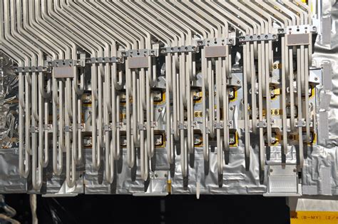
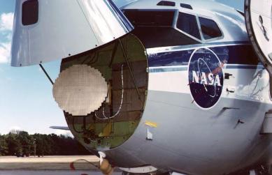
Figure 1 — Ka‑Band waveguide close‑up. Image Credit: NASA / GPM Mission (Public Domain).
This article summarizes architectural options (common‑cavity vs. hybrid), outlines design trade‑offs, highlights measurement considerations, and explains where such modules deliver system‑level value in SATCOM and radar. We intentionally avoid unpublished internal claims; instead, we rely on accepted engineering practice and representative figures from public literature and vendor specifications.
Design & Architecture
Design Objectives at Ka‑Band
- Low insertion loss (IL) with flat group delay in the passband
- Isolation ≥20–25 dB across temperature and mismatch ranges
- Robust VSWR behavior during rain fade / scan loss scenarios
- Shared thermal references; minimal drift under soak tests
Targets vary by topology, cavity Q, ferrite volume, and termination design.
Common‑Cavity Integration (Waveguide / Precision Housing)
The isolator junction (ferrite with bias) and the bandpass resonators share a machined enclosure. Fewer launches and shorter paths reduce discontinuities and often deliver lower insertion loss with superior linearity. Success hinges on seam‑current control, flange flatness (often <20 µm), plating quality, and shared heat‑spreading.
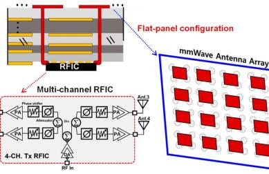
Substrate‑Level Hybrid (Microstrip / LTCC)
Isolator structures and filter resonators co‑reside on one substrate for compact front‑ends. Key challenges include magnetic leakage into resonators and temperature drift; EM–thermal co‑simulation and careful bias routing are mandatory to maintain tile‑to‑tile consistency.
Side‑by‑Side Hybrid Module
Filter and isolator are built as individual blocks assembled into one shielded housing. Although insertion loss can be slightly higher than the common‑cavity approach, this path is predictable and service‑friendly.
Key Trade‑Offs
| Goal | Design Lever | Trade‑Off | Ka‑Band Tip |
|---|---|---|---|
| Lower IL | High‑Q cavities; short transitions | Machining and tuning complexity rise | Control seam currents; ensure launch repeatability and finish quality |
| Higher Isolation | Ferrite volume/bias; termination load design | Thermal rise in the load | Model reverse power for 2:1–3:1 VSWR and hot conditions |
| Wider Passband | Coupling topology; multi‑resonator networks | Passband ripple / group‑delay variation | Flatten group delay in the service band and verify EVM |
| Array Consistency | Bias routing; symmetry; tolerances | Yield pressure | Characterize tile‑to‑tile phase/amplitude and set guard‑bands |
Measurement & Performance Considerations
Representative specifications for Ka‑Band isolators in vendor literature list insertion loss on the order of ~0.5–1.5 dB and isolation ≥20–25 dB, depending on frequency span and power class. Integrated modules aim to match or improve these figures while consolidating interfaces. When evaluating an integrated design, an honest test plan is essential:
- S‑parameters across temperature (cold/room/hot) and across the entire intended passband
- Load‑pull or mismatch stress (e.g., 2:1–3:1 VSWR) at target power with soak tests
- Group delay flatness and ACPR/EVM impact for the intended waveform
- Long‑duration reliability (thermal cycling, vibration if airborne)
Applications
SATCOM Gateways (Ka‑Band)
Placing the integrated module immediately after the PA (and before the antenna feed) shortens the path where reflections could stress active devices. The filter enforces masks while the isolator quietly dumps reverse power. The combined effect is more stable EIRP and cleaner spectra—especially valuable under rain‑fade or scan‑loss conditions that transiently elevate mismatch.
AESA Radar Tiles
Arrays demand tight channel matching. Shared mechanical references and fewer RF interfaces improve phase uniformity across tiles; field service is simpler with one tested module per channel. Designs should still allocate guard‑bands for cumulative tolerances across the array.
Related HzBeat Product Families
Explore our isolators and circulators that pair with Ka‑Band front‑ends:
Typical Coaxial Circulator · High‑Power Coaxial Circulator · Broadband Coaxial Circulator
Summary
Integrating an isolator with a bandpass filter is a pragmatic way to reduce interfaces and tune the RF path as a whole. At Ka‑Band, where mechanical tolerances, thermal gradients, and launch repeatability dominate outcomes, an integrated approach can deliver lower aggregate loss, better phase consistency, and more predictable behavior under mismatch—provided the design addresses ferrite biasing, termination thermal loads, and cavity or substrate Q.
FAQ
Q1: Does an integrated module always have lower insertion loss?
Not always. Lower total IL is common when a common‑cavity design removes multiple transitions and optimizes EM paths. However, aggressive passband width or isolation requirements can raise IL; co‑design is the key.
Q2: How should I size the termination load in the isolator section?
Model worst‑case reverse power under intended VSWR and ambient conditions, then add thermal margins. Validate with time‑domain power sweeps and soak tests.
Q3: Can this approach scale to E/F‑Band?
Yes, with precision waveguide or substrate‑integrated waveguide transitions. Mechanical tolerances and finish quality dominate above Ka‑Band; budget accordingly.
Q4: What about magnetless non‑reciprocal techniques?
Time‑varying networks and spatiotemporal modulation are promising for low‑power, highly integrated RFIC/SiP contexts. Today, ferrite remains the practical choice for high‑power front‑ends.
References (Selected)
- IEEE Transactions on Microwave Theory and Techniques (2024–2025): Reports on integrated front‑end modules achieving Ka‑Band passband performance with isolation ≥20–25 dB and low IL, depending on topology.
- Microwave Journal / EuMW Technical Digests (2024–2025): Trends in waveguide common‑cavity methods, mmWave transitions, and front‑end integration.
- Vendor Specifications (e.g., Mi‑Wave / HASCO / Pasternack): Typical Ka‑Band isolator specs with IL on the order of 0.5–1.5 dB and isolation ≥20–25 dB.
- Image Credit: NASA / Global Precipitation Measurement (GPM) Mission — Public Domain.
Relateds

About the Author

HzBeat Editorial Content Team
Sara is a Brand Specialist at Hzbeat, focusing on RF & microwave industry communications. She transforms complex technologies into accessible insights, helping global readers understand the value of circulators, isolators, and other key components.