Inside the Engineering of Low-Insertion-Loss Ferrite Isolators
Updated on:
Keywords: RF circulator, isolator
Introduction
In modern RF chains—whether you are building a phased‑array radar panel, a compact 5G/6G small cell, or a deep‑space telemetry downlink—the isolator is the quiet guardian that lets transmitters and receivers coexist without hurting each other. An isolator is a two‑port, non‑reciprocal passive component that lets power flow in the forward direction while strongly attenuating any reverse‑traveling energy. In practical systems, it protects power amplifiers from high VSWR events, improves load tolerance, and stabilizes gain‑phase behavior in tightly packed front‑ends.
Ferrite‑based devices dominate this category. Under a static magnetic bias (from permanent magnets or electromagnets), ferrimagnetic materials exhibit a gyromagnetic response that breaks reciprocity. Ferrite isolators and their three‑port cousins—RF circulators—exploit this physics to redirect reverse energy into a matched internal load or to the next port. When engineers talk about “inside the engineering of low‑insertion‑loss ferrite isolators,” they are really juggling a tightly coupled four‑way optimization: magnetic losses, conductor/dielectric losses, impedance matching, and thermal reliability.
1) What “low insertion loss” means in system budgets
Insertion loss (IL) is the additional attenuation introduced by inserting the isolator into the signal path, typically measured as −20·log₁₀|S21| in dB for a two‑port. In practice, a “low‑loss” ferrite isolator in L/S/C/X/Ku/Ka bands targets IL ≤ 0.2–0.5 dB over its guaranteed bandwidth. Pushing below 0.2 dB is challenging and usually forces trade‑offs—larger ferrite volume, better magnet uniformity, tighter machining tolerances, and premium plating—to keep magnetic and conductor losses down while preserving isolation.
- Noise figure and receiver sensitivity: Every 0.1 dB of IL after the LNA sabotages precious dB of sensitivity; therefore, isolators placed ahead of or near LNAs must be exceptionally low loss.
- Transmitter efficiency: In high‑power PAs, 0.3 dB IL is about 7% power wasted as heat before the antenna. Thermal margins and EIRP targets care about that.
- Linearity and stability: Good reverse isolation reduces load‑pull variability and mitigates oscillation risks in high‑gain loops.
Tips:
Ask suppliers for swept IL/Isolation/VSWR plots across the full guaranteed bandwidth.
2) Ferrite material, bias, and resonance control
Ferrite materials are engineered for the operating band and temperature range. Key levers are saturation magnetization (Ms), linewidth (ΔH), and dielectric loss tangent. A higher Ms supports higher frequency operation under practical magnet sizes; a narrow ΔH reduces magnetic losses (less “friction” in precession), directly helping IL. Low dielectric loss ferrites and carefully chosen bonding epoxies keep tanδ small. Bias uniformity is equally important: non‑uniform magnetization produces phase errors, ripple, and elevated IL.
Designers often sweep bias field H to place the gyromagnetic resonance sufficiently away from the band center while achieving the required non‑reciprocity. The trick is to bias “just enough”: too little and isolation collapses; too much and magnetic losses rise or the device drifts with temperature. Temperature compensation is handled via magnet grade selection and thermal paths that keep the ferrite at steady operating temperature.
3) Junction geometry and the path to low loss
Different physical topologies exist—microstrip, stripline, waveguide, and coaxial. For low‑IL isolator designs, each has canonical tactics:
- Microstrip and stripline: Minimize conductor loss by using thick copper, low‑roughness foils, and high‑Q plating (e.g., silver on critical surfaces). Choose laminates with low Dk and low loss tangent (PTFE, LCP, advanced ceramics). Ferrite tiles bond to the circuit, with carefully designed ground via fences to keep fields collimated and reduce radiation loss. Launch and transition design is crucial since return‑loss miscues inflate apparent IL.
- Coaxial: Coax junctions can be very low loss due to circular symmetry and uniform fields. But precise center‑conductor alignment, ferrite puck geometry, and impedance transforms are needed to keep mode conversion at bay.
- Waveguide: For higher frequencies or high power, waveguide junctions provide superb Q. Surface finish, corner rounding, and choke grooves around the ferrite discs control current crowding and reduce wall losses. Properly designed loads maintain isolation without leaking heat back into the cavity.
4) Matching networks and S‑parameter discipline
Low‑insertion‑loss engineering is, in many ways, disciplined S‑parameter management. Designers obsess over Smith‑chart trajectories: keeping the forward transmission magnitude near 0 dB and the phase smooth, while return loss better than 20 dB over the passband. Matching elements—quarter‑wave transformers, tapered lines, or capacitive/inductive posts—shape the impedance seen by the ferrite junction. Because ferrites are dispersive, wideband low‑IL behavior requires trade‑offs: broader bandwidth typically raises minimum IL unless volume or magnet strength is increased.
| Parameter | Low‑Loss Target | Comments |
|---|---|---|
| Insertion Loss | ≤ 0.2–0.5 dB | Bandwidth dependent; tighter for narrowband, relaxed for ultra‑wideband. |
| Isolation | ≥ 18–25 dB | Higher isolation sometimes trades a bit of IL. |
| VSWR | ≤ 1.20–1.30 | Good return loss minimizes ripple that inflates IL. |
| Power Handling | Up to kW (waveguide) | Thermal design and load resistor mass dominate. |
| Temperature Range | −40 to +85 °C (typ.) | Magnet grade and CTE matching matter. |
| Size/Weight | Application‑dependent | Miniaturization pressures increase IL unless materials improve. |
5) Thermal and power handling
Even small IL numbers become heat in high‑power links. At 50 W forward power, 0.3 dB IL dissipates roughly 3.4 W. That heat largely resides in the ferrite and the matched load on the isolated port. Engineers therefore integrate high‑conductivity paths—copper bases, plated waveguide walls, or graphite pads—toward the chassis. In microstrip/stripline assemblies, thermal vias under the ferrite tiles and under the load resistor help. Material coefficients of thermal expansion (CTE) between ferrite, substrate, adhesives, and metalwork must be harmonized to prevent stress and detuning.
6) Measuring and verifying low insertion loss
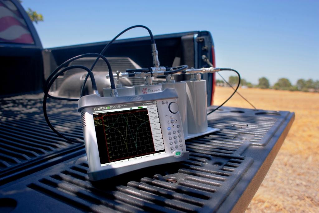
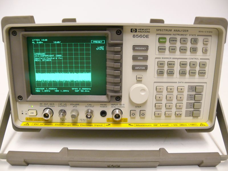
S‑parameter verification uses a calibrated vector network analyzer (VNA) with high‑quality coaxial, microstrip, or waveguide fixtures. Good practice includes TRL or SOLT calibration near the device plane, de‑embedding of fixturing, and temperature‑controlled sweeps to expose drift. Complementary spectrum analyzer checks measure reverse isolation under modulated carriers and look for spurious content when the device is driven near its power limit. Time‑domain transforms (TDR/TDT) help localize discontinuities that cause ripple and excess IL.
7) Application snapshots
- 5G/6G radio units: Low‑IL isolators keep PA efficiency high in small cells and protect against outdoor antenna mismatch, especially under dynamic beamforming.
- Phased‑array radar: Distributed RF circulators/isolators in each TRX channel stabilize gain blocks and prevent coupling that forms grating lobes or oscillations.
- Satellite payloads: Waveguide isolators with very low IL and high power handling ensure EIRP budgets are met and back‑off margins stay reasonable.
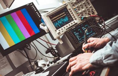
- Test & measurement: VNAs and PAs use internal isolators to improve match and accuracy of S-parameter and power sweeps.
8) Practical procurement checklist for low‑IL isolators
Performance
- Guaranteed IL across bandwidth (typical vs. max)
- Isolation and VSWR curves, not just single‑point specs
- Phase linearity and group delay ripple
Materials & Build
- Ferrite composition, linewidth (ΔH), and magnet grade
- Plating stack and surface roughness on current‑carrying paths
- Bond thickness control, adhesive type, and CTE matching
Reliability
- Thermal paths, load resistor rating, and burn‑in
- Environmental testing (shock, vibe, temp cycling, humidity)
- Lot‑to‑lot IL and isolation distribution (Cp/Cpk)
9) Where RF circulator thinking meets isolator optimization
Many design insights are shared across RF circulator and isolator engineering. The non‑reciprocal junction physics is common; what differs is load strategy and port mapping. Teams achieving sub‑0.3 dB IL in circulators often transfer those techniques to isolators: improved bias homogeneity, tighter ferrite parallelism, and better microwave transitions. From a product‑line perspective, standardizing on ferrite blanks and magnet assemblies across SKUs reduces variation, which stabilizes IL and isolation in volume production.
Conclusion
Low‑insertion‑loss ferrite isolators are the hallmark of mature microwave engineering. They embody precise materials science, rigorous RF matching, careful thermal design, and robust manufacturing control. As 5G/6G, multi‑band SATCOM, and advanced radar demand ever‑tighter link budgets in ever‑smaller volumes, the winners will be the designs that squeeze IL down without giving up bandwidth, power, or reliability. Mastering these levers transforms an ordinary non‑reciprocal component into a quiet determinant of system‑level performance.
FAQ
What makes ferrite isolators “low loss” compared with alternatives?
High‑quality ferrites with narrow linewidth, uniform bias fields, smooth plating, and precision matching keep magnetic and conductor losses minimal. Good return loss also prevents ripple that would inflate IL.
Can I use an RF circulator instead of an isolator?
Sometimes. A circulator with a well‑matched load on the third port is functionally an isolator. However, dedicated isolators may offer lower IL in the same footprint because loading is optimized for the use case.
How does temperature affect insertion loss?
Bias changes with temperature and ferrite parameters drift; the result is minor IL movement across the spec’d range. Designs use magnet selection and thermal paths to keep drift small.
What is a realistic IL for X‑band waveguide isolators?
Values of 0.2–0.4 dB across several hundred MHz bandwidth are common; narrower bands can go lower with larger magnets and careful machining.
Does miniaturization always increase IL?
It tends to. Smaller ferrite volume and tighter bends increase loss, but materials and matching advances can claw some of it back.
Relateds
About the Author

HzBeat Editorial Content Team
Sara is a Brand Specialist at Hzbeat, focusing on RF & microwave industry communications. She transforms complex technologies into accessible insights, helping global readers understand the value of circulators, isolators, and other key components.