From 2 GHz to 40 GHz: How One RF Circulator Covers Countless Applications | HzBeat
Updated on:
Keywords: wideband RF circulator, 2-40 GHz circulator, broadband ferrite circulator, non-reciprocal device, low insertion loss, high isolation, S-band, C-band, X-band, Ku-band, Ka-band, radar, VSAT, satcom, 5G backhaul, HzBeat
Summary: Modern radar, satcom, and 5G backhaul are compressing schedules while expanding spectral ambitions. A single wideband RF circulator spanning 2–40 GHz promises simpler BOM, faster qualification, and reuse across platforms—provided insertion loss, isolation, VSWR, and power handling stay within spec. This piece breaks down what it takes, where it fits, and how to deploy it responsibly.
1) Why 2–40 GHz matters now
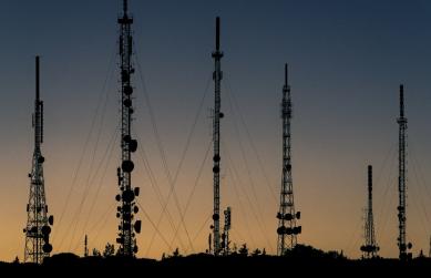
S-, C-, X-, Ku-, and Ka-band programs are converging in roadmaps—from coastal surveillance radars and airborne SAR to VSAT terminals and high-throughput satellites (HTS). Integrators want fewer SKUs and more common parts. The appeal is obvious: a single wideband circulator lets front-end modules share the same non-reciprocal core across multiple bands, reducing tooling changeovers and simplifying spares.
| Band | Nominal range | Representative applications |
|---|---|---|
| S-band | 2–4 GHz | Air traffic & weather radar, telemetry, satcom ground |
| C-band | 4–8 GHz | Surveillance radar, maritime, 5G backhaul |
| X-band | 8–12 GHz | SAR/ISAR, coastal & naval radar, TT&C |
| Ku-band | 12–18 GHz | VSAT, in-flight connectivity, feeder links |
| Ka-band | 26.5–40 GHz | HTS payloads, millimeter-wave links, automotive radar R&D |
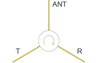
But the physics isn’t free. As frequency increases, magnetic biasing, ferrite dispersion, and conductor/dielectric loss all conspire to raise insertion loss and depress isolation. Any 2–40 GHz circulator must balance material choice, topology, and matching to avoid trading bandwidth for performance collapse.
Program drivers in 2025–2028
- Multi-theater maritime & coastal radar upgrades demanding S/X dual-band reuse.
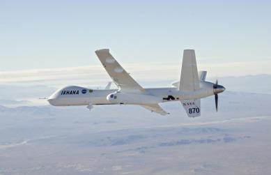
- Explosive growth in VSAT / HTS ground and in‑flight connectivity (Ku→Ka migration).
- 5G/6G microwave backhaul densification needing flexible front‑end reuse.
- ATE/R&D labs consolidating to wideband non‑reciprocal devices for faster bring‑up.
SEO long‑tail coverage: wideband RF circulator 2–40 GHz, S‑band circulator for weather radar, Ku‑band circulator for VSAT, Ka‑band ferrite circulator for HTS gateways, broadband non‑reciprocal device low insertion loss, high isolation circulator for multi‑band radar.
2) Design pillars for wideband ferrite circulators
Ferrite recipe & magnetic bias
Choosing a ferrite with suitable saturation magnetization and linewidth is foundational. Wider bands push designers toward carefully doped garnets and precise biasing field profiles (often with magnet shims or multi-piece magnets) to flatten response. Thermal drift must be modeled from −40 °C to +85 °C with derating curves for isolation.
Topology: microstrip, drop‑in, coaxial, waveguide
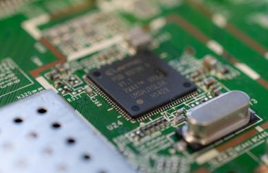
- Microstrip: compact, PCB-level integration; ideal for S/C/X band TRMs.
- Drop‑in: screw-mount convenience with tuned launch; popular in 6–18 GHz modules.
- Coaxial: robust power handling and easy test access.
- Waveguide: lowest loss and best power handling at Ku/Ka, at the cost of size.
Matching networks for bandwidth
Broadband performance comes from distributed matching (stubs, tapered lines) and, where necessary, miniature lumped compensation. Designers aim for return loss > 14 dB and isolation > 18–20 dB across sub-bands, with insertion loss minimized through conductor plating and surface finish consistency.
| Sub‑band | Example target IL | Typical ISO | Notes |
|---|---|---|---|
| 2–6 GHz | ≤0.6 dB | ≥22 dB | Microstrip/Drop‑in; focus on PCB stack‑up and vias |
| 6–18 GHz | ≤0.9 dB | ≥20 dB | Drop‑in/Coax; tighter machining & plating control |
| 18–40 GHz | ≤1.2 dB | ≥18 dB | Waveguide preferred; flange flatness critical |
Additional long‑tail: broadband 6–18 GHz circulator, 18–40 GHz Ka‑band circulator with low VSWR, microstrip circulator for phased array T/R module, drop‑in circulator for X‑band radar, waveguide circulator WR‑28 high power.
Thermal and power integrity
Across 2–40 GHz, forward power and reflected power vary widely with duty cycle and waveform. Heatsinking (CuW bases, AlN ceramics), adhesive choice, and torque repeatability directly impact reliability. Pulsed high‑power radar requires special attention to peak vs. average power and to load‑pull edge cases during field operation.
3) Where a single wideband circulator fits best
- Multi‑band radar platforms: reuse the same circulator core for S/X maritime radar variants, simplifying spares across fleets.
- VSAT & HTS gateways: Ku today, Ka tomorrow—keep the same BOM slot while upgrading RFICs and filters.
- 5G/6G backhaul & telemetry: C/X links for backhaul, S‑band for TT&C—standardize the non‑reciprocal stage.
- R&D platforms & ATE: a single golden device shortens bring‑up and lets engineers sweep bands without swapping fixtures.
Beyond the headline bands, niche but valuable opportunities include precision agriculture radar (X‑band), harbor monitoring (S/C), and airborne ISR links migrating from Ku to Ka. In each case, a shared mechanical circulator family accelerates variant launches.
Related internal links: Dual‑ridge waveguide circulator · Typical drop‑in circulator.
4) Performance targets you can actually hold
Every program negotiates its own trade‑offs. For a practical 2–40 GHz family, engineers commonly pursue:
- Insertion loss: ≤ 0.4–0.6 dB in S/C; ≤ 0.6–0.9 dB in X/Ku; ≤ 1.0–1.2 dB in Ka (sub‑band averaged).
- Isolation: ≥ 18–22 dB across bands, with peak regions > 25 dB where feasible.
- Return loss: > 14–16 dB typical, tighter in narrow sub‑bands.
- Power handling: specify CW and peak separately; validate with worst‑case VSWR load‑pull.
Qualification should include temperature chambers, vibration, and long‑duration RF soak at worst‑case mismatch. Record torque settings and re‑test after thermal cycling—the magnet bias stack can subtly shift.
5) Integration patterns by package
Microstrip / SMT
Ideal for TRMs and phased arrays. Keep ground stitching dense around the launch. Use controlled‑impedance stackups and consider ENEPIG or equivalent finish for stable RF contact.
- Long‑tail: SMT RF circulator for phased array, microstrip circulator low insertion loss S‑band, X‑band SMT circulator high isolation.
Drop‑in
A favorite in 6–18 GHz blocks. Ensure flatness and torque spec on the baseplate; thin thermal interface material helps. Provide test coupons for incoming inspection.
- Long‑tail: 6–18 GHz drop‑in circulator for radar T/R module, X‑band drop‑in circulator for SAR.
Coaxial
Great for lab use and systems requiring field‑replaceable parts. Choose connectors matched to band and power (SMA/2.92/2.4 mm, N, TNC).
- Long‑tail: coaxial RF circulator for test benches, broadband coax circulator 2–18 GHz, Ka‑capable 2.92 mm circulator.
Waveguide
Unbeatable for Ka‑band power and efficiency. Confirm flange standards (e.g., WR‑28) and gasket plan, and align with radar or satcom maintenance practices.
- Long‑tail: WR‑28 waveguide circulator high power, Ku‑band waveguide circulator low loss, Ka‑band ferrite waveguide circulator for HTS.
6) Sourcing & road‑mapping with HzBeat
HzBeat supports custom RF circulators and isolators spanning 20 MHz–200 GHz with microstrip, drop‑in, coaxial, and waveguide formats. For wideband needs, we typically partition the 2–40 GHz span into sensible sub‑families to protect IL/ISO while keeping a common mechanical footprint.
Explore product lines: Microstrip Circulators • Drop‑in Circulators • Coaxial Circulators • Waveguide Circulators • Waveguide Isolators
For OEM/ODM or small‑batch prototyping, contact: [email protected]
Long‑tail: custom RF circulator supplier, OEM/ODM ferrite circulator China, Ka‑band circulator manufacturer, wideband circulator 2–40 GHz vendor.
7) Buying guide & selection matrix
| Use case | Preferred package | Quick targets | Notes |
|---|---|---|---|
| S‑band weather radar | Microstrip/Drop‑in | IL ≤0.6 dB; ISO ≥22 dB | Thermal pad + dense vias |
| X‑band SAR | Drop‑in/Coax | IL ≤0.9 dB; ISO ≥20 dB | Gold finish, torque spec |
| Ku VSAT | Drop‑in/Waveguide | IL ≤0.9 dB; ISO ≥20 dB | Connector/WR standard |
| Ka HTS gateway | Waveguide (WR‑28) | IL ≤1.2 dB; ISO ≥18 dB | Flange flatness critical |
8) Compliance, reliability & environmental
- Compliance: RoHS/REACH, conflict‑free materials, export classifications.
- Screening: burn‑in, HASS, thermal cycling, vibe & shock per program spec.
- Documentation: full S‑parameter set, torque instructions, COC.
9) Integration pitfalls & mitigations
- Mismatch escalation at band edges → mitigation: tapered lines + EM co‑sim of launch.
- Thermal drift of magnet bias → mitigation: material choice, shim strategy, re‑torque after cycles.
- Connector/WR inconsistency → mitigation: frozen standards (SMA/2.92/2.4, WR‑28), incoming gauge.
FAQ
Q1. Can a single circulator truly span 2–40 GHz without gaps?
In practice, high‑quality wideband solutions are engineered as a family sharing mechanics and interfaces, each optimized for sub‑ranges (e.g., 2–6, 6–18, 18–40 GHz). This protects insertion loss and isolation and simplifies qualification.
Q2. How do I keep isolation high at Ka‑band?
Use waveguide where possible, pay attention to flange flatness and gasket uniformity, and maintain magnet bias stability over temperature. Board‑level implementations should model conductor loss and surface roughness carefully.
Q3. What about power handling for pulsed radar?
Specify both CW and peak. Validate with load‑pull at worst VSWR and duty cycle. Heatsinking and base material choices (CuW, AlN) directly influence margin.
Q4. How do I qualify a vendor part quickly?
Define a common test plan: IL/ISO/RL vs. frequency, temperature sweeps, torque spec, and re‑verification after environmental cycling. Keep fixtures consistent across vendors.
References
- Microwave textbooks and standards on ferrite non‑reciprocal devices.
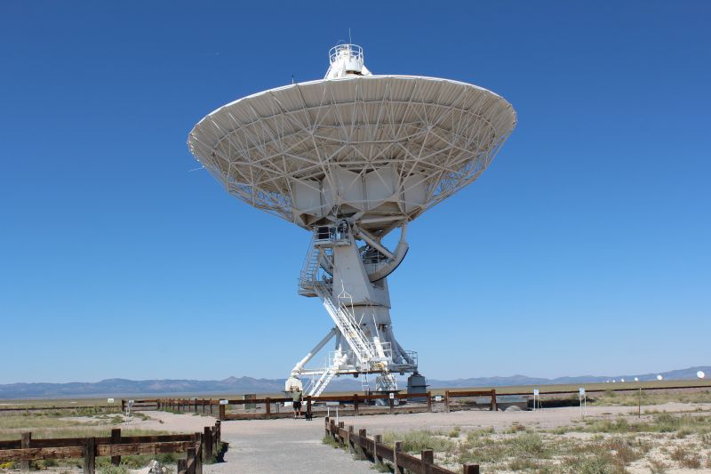
- NRAO VLA overview (context for ground‑segment dishes).
- Manufacturers’ application notes on wideband matching and magnet bias control.
Relateds
About the Author

HzBeat Editorial Content Team
Marketing Director, Chengdu Hertz Electronic Technology Co., Ltd. (Hzbeat)
Keith has over 18 years in the RF components industry, focusing on the intersection of technology, healthcare applications, and global market trends.