RF Circulator/Isolator Performance Testing Guide: VNA Measurement Methods Explained
Updated on:
Keywords: RF circulator, RF isolator, VNA measurement, S-parameters, insertion loss, isolation, return loss, VSWR, ferrite devices, RF testing, calibration, de-embedding
Abstract. RF circulators and isolators are non-reciprocal ferrite components that protect transmitters, stabilize power amplifiers, and route energy between ports with minimal loss in the forward direction and high attenuation in the reverse direction. For procurement managers and design engineers alike, the most decisive step is not in the purchase order but in the measurement bench: a precise, repeatable vector network analyzer (VNA) method that proves insertion loss, isolation, match, and power-handling readiness. This guide distills lab-proven procedures into a step-by-step workflow—calibration and fixturing, port mapping, S-parameter recipes, de-embedding, uncertainty awareness, acceptance criteria, and reporting—so that your next shipment inspection or EVT/DVT sign-off is both defensible and fast.
We focus on three practical realities: (1) circulator port orientation and reference planes often cause mistakes; (2) fixtures and adapters (SMA, SMPM, 2.92 mm, waveguide transitions, microstrip launch boards) dominate the error budget if not accounted for; and (3) VNA calibration discipline (SOLT/TRL/Unknown-Thru, power leveling, averaging, IF bandwidth) makes or breaks repeatability. Along the way we provide checklists, numeric targets, and pitfalls to avoid, with references to Keysight, Rohde & Schwarz, and IEEE sources for deeper reading.
1) Test Topology and Port Mapping
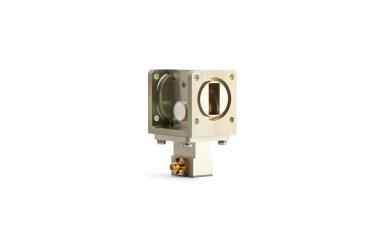
Three-port circulators route power port-1 → port-2 → port-3 → port-1. Mis-mapping these directions is the #1 cause of “bad” isolation plots. Draw a triangle and label your DUT before any cable touches metal. For isolators (two-port), the forward direction is marked with an arrow or “IN/OUT.” When in doubt, start with a low-power CW source and power meter to sanity-check the intended routing.
2) Fixtures, Adapters, and Reference Planes

Every adapter is a potential source of ripple. Keep transitions minimal and characterized: e.g., SMA male → 2.92 mm female pairs, torque to 0.9 N·m with a calibrated wrench, and avoid bending memory in phase-stable cables. For microstrip or drop-in parts, use a launcher board with controlled impedance and back-drilled vias, then TRL or Unknown-Thru to place reference planes at the DUT pads. For waveguide parts (WR-xx), the waveguide-to-coax transition must be included in the cal kit or de-embedded by measurement of the transition alone.
3) VNA Calibration Discipline
Choose the right method for your connector family and bandwidth:
- SOLT: Versatile and fast for coaxial interfaces with well-modeled standards (Short-Open-Load-Thru).
- TRL: Superior for planar launches and broadband work when you can fabricate line/reflect standards on the same PCB stack-up.
- Unknown-Thru / ECal: Speeds setup and reduces user error; ideal for production screening and incoming inspection.
Set IF bandwidth (e.g., 1–3 kHz), averaging (2–8), and output power (−10 to 0 dBm for small-signal S-parameter tests) to balance speed and noise floor. Always verify cal by measuring a known good adapter or airline; a flat, near-0 dB Thru trace is your friend.
4) S-Parameter Recipes for Non-Reciprocal Devices
For a 3-port circulator, measure at least the following paths:
- Forward IL: S21 (1→2), S32 (3→2), S13 (1→3) depending on your labeling—confirm with your triangle map.
- Isolation: The reverse of the above (e.g., S12, S23, S31). Peak isolation should align with design center frequency.
- Match: S11, S22, S33 across band; poor match can masquerade as high IL.
For a 2-port isolator, capture S21 (forward IL), S12 (reverse isolation), and S11/S22 (return loss). Add group delay if system timing matters.
5) De-Embedding and Fixture Effects
When fixtures are non-trivial, build a 2x-Thru or separate “left” and “right” fixtures and apply port-extension or embedding/de-embedding models. Keep a golden board per product line to monitor drift. Save Touchstone files of fixtures for reuse and auditing.
6) Uncertainty, Repeatability, and Guard Bands
Quantify the Type A/B uncertainties: connector repeatability, cable flex, temperature, calibration drift, VNA trace noise. As a rule of thumb, isolation margins under 3 dB are risky for pass/fail; set guard bands (e.g., spec 23 dB → accept at ≥ 24 dB) to protect yield.
7) Practical Acceptance Criteria and Reporting
Adopt numeric, frequency-wise masks for IL/ISO/RL. Include lot ID, serial numbers, fixture ID, cal date, and operator on each report. Export calibrated S-parameters as Touchstone (.s2p/.s3p) and attach plots (linear frequency + log magnitude) with consistent axes.
Acceptance Criteria
- Insertion Loss (IL): Typically ≤ 0.3–0.6 dB across the specified band for premium X/Ku/Ka-band units; ≤ 1.0 dB for compact SMT or wideband compromises. Verify flatness and note temperature drift.
- Isolation (ISO): Common thresholds are ≥ 18–23 dB for compact parts and ≥ 23–30 dB for performance-oriented designs; high-power waveguide devices may exceed 30 dB over narrower bands.
- Return Loss (RL / VSWR): Aim for RL ≥ 14 dB (VSWR ≤ 1.5:1) as a good baseline; ≥ 18 dB for premium products. Check all ports and both directions (forward and reverse paths).
- Phase/Amplitude Balance: In phased arrays, phase consistency through the circulator path matters; log phase linearity versus frequency if required.
- Power Readiness: Perform low-power S-parameter screening, then (if applicable) step into load-pull or power-sweep benches with proper cooling and reflected-power monitoring.
8) Quick Checklist (Tape to the Rack)
- Label circulator ports clockwise; verify with a low-power sanity test.
- Use fresh torque-wrenched adapters; avoid unnecessary transitions.
- Pick the right cal (SOLT/TRL/ECal) and verify with a known Thru.
- Stabilize cables; use strain relief and mark reference orientation.
- Average traces sensibly; don’t over-tighten IF BW (speed vs noise).
- De-embed fixtures; maintain golden boards and Touchstone libraries.
- Set guard bands; document environment, operator, and cal date.
FAQ
- Q: How do I measure isolation on a three-port circulator with a two-port VNA?
A: Connect the VNA to the two ports involved in the reverse path and terminate the third port with a well-matched 50-ohm load. Repeat for each reverse path and rotate terminations accordingly. - Q: My isolation curve shows deep notches—cable issue or DUT issue?
A: First wiggle the cables slightly and see if the notch moves; if yes, it’s likely a connector/cable repeatability artifact. If the notch is stationary, check fixture resonances or DUT magnetization. - Q: When should I prefer TRL over SOLT?
A: Whenever your reference planes are on a custom PCB launch and you can fabricate precise line standards on-stack. TRL is robust for broadband work and reduces model dependency. - Q: What pass/fail should I use for SMT isolators?
A: As a starting point, IL ≤ 0.8–1.0 dB, ISO ≥ 18–22 dB, RL ≥ 14 dB, but tune to your vendor’s datasheet and your system budget.
Conclusion
Bottom line: A circulator/isolator passes qualification when forward loss is low and flat, reverse paths are strongly attenuated, and all ports are well matched—at the intended reference planes. With disciplined calibration, minimal and characterized fixtures, and clear guard bands, VNA-based verification becomes fast, reproducible, and defensible across labs and time.
Relateds

About the Author

HzBeat Editorial Content Team
Sara is a Brand Specialist at Hzbeat, focusing on RF & microwave industry communications. She transforms complex technologies into accessible insights, helping global readers understand the value of circulators, isolators, and other key components.