Home/ Microstrip Isolator/ Broadband Microstrip Isolator
Broadband Microstrip Isolator
S Band, C Band, X Band, Ku Band, K Band, (2GHz-28GHz)
- The following products are broadband Microstrip Isolators designed with a compact form factor, covering the frequency range from the S-band to the K-band, with a maximum relative bandwidth of up to 100%.
Key Features & Advantages
- Ultra-Wide Operating Bandwidth: Covers multiple frequency bands, serving multiple purposes with one device and simplifying inventory and design.
- High Isolation: Effectively suppresses reflected signals, providing superior protection for preceding circuits (e.g., power amplifiers).
- Low Insertion Loss: Minimizes signal power loss.
- High Return Loss: Indicates good impedance matching at both the input and output ports, reducing reflections caused by the device itself.
- Compact Size and Light Weight: The planar microstrip structure makes it much smaller and lighter than waveguide or stripline structures, making it ideal for high-density integrated systems.
- Excellent Thermal Stability: Utilizes high-performance ferrite materials and optimized design for stable operation over a wide temperature range (e.g., -55°C to +85°C).
- High Power Handling Capacity: Can be designed for low-power or medium-power versions based on requirements, meeting the needs of different application scenarios.
Typical Applications
- Transmitter Protection: Placed between the power amplifier and the antenna to prevent reflected power caused by antenna mismatch from damaging expensive power amplifier tubes.
- Frequency Source Stabilization: Used at the output of oscillators (e.g., DRO, VCO) to isolate the oscillator from load variations, improving frequency stability and phase noise performance.
- Test and Measurement Systems: Used in equipment like Vector Network Analyzers to improve the output match accuracy of signal sources and protect them.
- Electronic Warfare Systems: Ensure unidirectional signal flow in broadband receiver and transmitter chains, enhancing system dynamic range and anti-jamming capability.
- Communication Base Stations: Used in transmit/receive paths for microwave relays, satellite communication systems, etc., to improve signal quality and system reliability.
- Radar Systems: Protect radar transmitters and are used in receive channels to improve performance.
Electrical Performance Table and Product Appearance
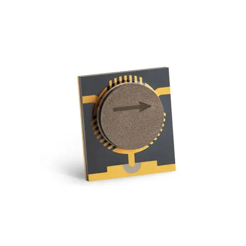
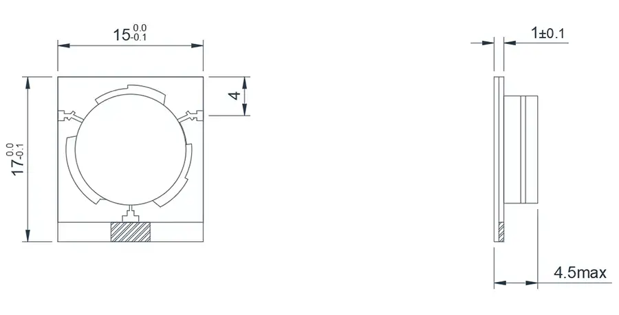
2.0~6.0GHz Broadband Microstrip 'T' junction Isolator
Model
Frequency(GHz)
BW Max
Insertion loss(dB) Max
Isolation(dB)Min
VSWR Max
operating temperature(℃ )
PK/CW/RP(Watt)
Direction
HMITA20T60G-B⬇
2.0~6.0
FULL
1.2(1.4)
11(10)
1.7
-55~+85℃
30/10/10
Clockwise
HMITB20T60G-B⬇
2.0~6.0
FULL
1.2(1.4)
11(10)
1.7
-55~+85℃
30/10/10
Counter Clockwise
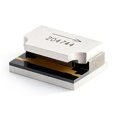
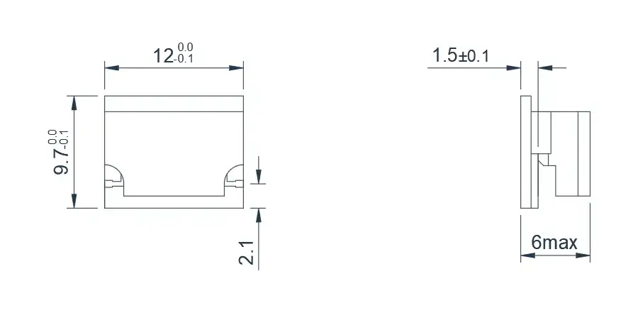
6.0~18.0GHz Edge Guide Mode Microstrip Isolator
Product Overview
The following products are edge mode isolators, covering the C-Band, X-Band, and Ku Band frequency ranges. The principle of edge mode isolators is based on the gyromagnetic effect of ferrite in the presence of a constant magnetic field and a perpendicular microwave field. This gyromagnetic effect results in a non-reciprocal transverse field shift in the propagation constant of electromagnetic waves transmitted on microstrip lines with ferrite substrates. As a result, the energy of the forward-traveling wave is concentrated along one edge of the microstrip, while the energy of the backward-traveling wave is concentrated along the opposite edge. Therefore, this wave can be considered to be guided by the edge of the conductor, hence the term "edge mode."
Model
Frequency(GHz)
BW Max
Insertion loss(dB) Max
Isolation(dB)Min
VSWR Max
operating temperature(℃ )
PK/CW/RP(Watt)
Direction
HMITA60T180G-B⬇
6.0~18.0
FULL
1.0(1.3)
15
1.65
-55~+85℃
30/10/1
Clockwise
HMITB60T180G-B⬇
6.0~18.0
FULL
1.0(1.3)
15
1.65
-55~+85℃
30/10/1
Counter Clockwise
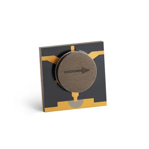
6.0~18.0GHz Broadband Microstrip 'T' junction Isolator
Model
Frequency(GHz)
BW Max
Insertion loss(dB) Max
Isolation(dB)Min
VSWR Max
operating temperature(℃ )
PK/CW/RP(Watt)
Direction
HMITA60T180G-B2⬇
6.0~18.0
FULL
1.0(1.2)
12(11)
1.65
-55~+85℃
30/10/1
Clockwise
HMITB60T180G-B2⬇
6.0~18.0
FULL
1.0(1.3)
15
1.65
-55~+85℃
30//10/1
Counter Clockwise
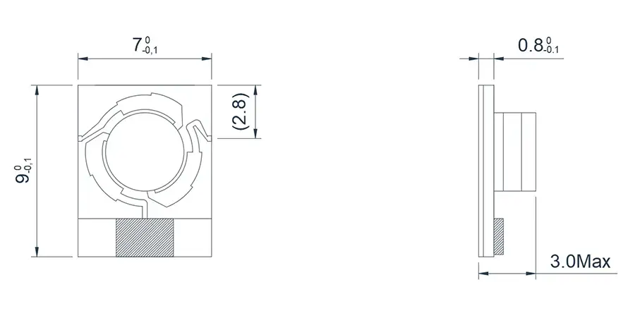
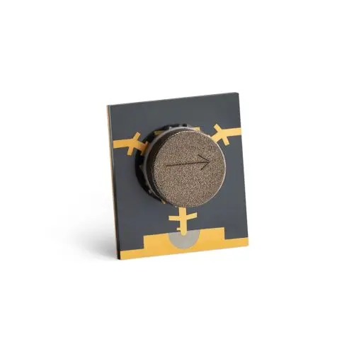
8.0~12.0GHz Broadband Microstrip 'T' junction Isolator
Model
Frequency(GHz)
BW Max
Insertion loss(dB) Max
Isolation(dB)Min
VSWR Max
operating temperature(℃ )
PK/CW/RP(Watt)
Direction
HMITA80T120G-B⬇
8.0~12.0
FULL
0.5
19
1.3
-55~+85℃
20/10/3
Clockwise
HMITB80T120G-B⬇
8.0~12.0
FULL
0.5
19
1.3
-55~+85℃
20/10/3
Counter Clockwise
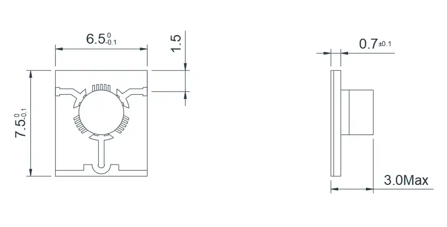
18.0~28.0GHz Broadband Microstrip 'T' junction Isolator
Model
Frequency(GHz)
BW Max
Insertion loss(dB) Max
Isolation(dB)Min
VSWR Max
operating temperature(℃ )
PK/CW/RP(Watt)
Direction
HMITA180T280G-B⬇
18.0~28.0
FULL
0.8
16
1.3
-55~+85℃
10/2/-
Clockwise
HMITB180T280G-B⬇
18.0~28.0
FULL
0.8
16
1.3
-55~+85℃
10/2/-
Counter Clockwise
About HzBeat
HzBeat is a leading RF component manufacturer specializing in RF circulators and isolators, as a global supplier of RF circulators and isolators (20MHz–200GHz), we providing microstrip, drop-in, coaxial, and waveguide solutions for communication systems, radar, satellite, and medical imaging.
For detailed technical documentation, sample requests, or customization needs, please do not hesitate to contact us. — we respond within 24 hours to ensure you get precise solutions for your design.
Customization & Selection Guide
- Operating Band:Ensure it covers all frequencies required by your system.
- Power Handling Capacity:Select based on your system's transmit power (average and peak), allowing a certain margin.
- Performance Requirements:Define specific requirements for Insertion Loss, Isolation, and VSWR/Return Loss.
- Environmental Conditions:Consider operating temperature range, vibration, humidity, etc.
- Cost & Delivery:Balance cost and project timeline while meeting performance requirements.
Why Choose Our Product
- Profound Technical Expertise:We have over 18 years of R&D experience in ferrite materials and microwave magnetics.
- Fully Automated Production Lines:Ensure consistent excellence and reliability in every unit.
- Professional Application Support:Our engineering team provides timely technical selection, customization, and failure analysis services.
- Competitive Pricing & Lead Times:Economies of scale from mass production enable us to respond quickly to your orders.
Related Products
Questions? Feel Free to Reach Out Via Message.
Tell us frequency band, target IL/Isolation/VSWR, power level and timeline — we’ll match the best topology and deliver S-parameters.We will contact you within 24 hours.
| Model | Frequency(GHz) | BW Max | Insertion loss(dB) Max | Isolation(dB)Min | VSWR Max | operating temperature(℃ ) | PK/CW/RP(Watt) | Direction |
|---|---|---|---|---|---|---|---|---|
| HMITA20T60G-B⬇ | 2.0~6.0 | FULL | 1.2(1.4) | 11(10) | 1.7 | -55~+85℃ | 30/10/10 | Clockwise |
| HMITB20T60G-B⬇ | 2.0~6.0 | FULL | 1.2(1.4) | 11(10) | 1.7 | -55~+85℃ | 30/10/10 | Counter Clockwise |
6.0~18.0GHz Edge Guide Mode Microstrip Isolator
Product Overview
The following products are edge mode isolators, covering the C-Band, X-Band, and Ku Band frequency ranges. The principle of edge mode isolators is based on the gyromagnetic effect of ferrite in the presence of a constant magnetic field and a perpendicular microwave field. This gyromagnetic effect results in a non-reciprocal transverse field shift in the propagation constant of electromagnetic waves transmitted on microstrip lines with ferrite substrates. As a result, the energy of the forward-traveling wave is concentrated along one edge of the microstrip, while the energy of the backward-traveling wave is concentrated along the opposite edge. Therefore, this wave can be considered to be guided by the edge of the conductor, hence the term "edge mode."
Model
Frequency(GHz)
BW Max
Insertion loss(dB) Max
Isolation(dB)Min
VSWR Max
operating temperature(℃ )
PK/CW/RP(Watt)
Direction
HMITA60T180G-B⬇
6.0~18.0
FULL
1.0(1.3)
15
1.65
-55~+85℃
30/10/1
Clockwise
HMITB60T180G-B⬇
6.0~18.0
FULL
1.0(1.3)
15
1.65
-55~+85℃
30/10/1
Counter Clockwise
6.0~18.0GHz Broadband Microstrip 'T' junction Isolator
Model
Frequency(GHz)
BW Max
Insertion loss(dB) Max
Isolation(dB)Min
VSWR Max
operating temperature(℃ )
PK/CW/RP(Watt)
Direction
HMITA60T180G-B2⬇
6.0~18.0
FULL
1.0(1.2)
12(11)
1.65
-55~+85℃
30/10/1
Clockwise
HMITB60T180G-B2⬇
6.0~18.0
FULL
1.0(1.3)
15
1.65
-55~+85℃
30//10/1
Counter Clockwise
8.0~12.0GHz Broadband Microstrip 'T' junction Isolator
Model
Frequency(GHz)
BW Max
Insertion loss(dB) Max
Isolation(dB)Min
VSWR Max
operating temperature(℃ )
PK/CW/RP(Watt)
Direction
HMITA80T120G-B⬇
8.0~12.0
FULL
0.5
19
1.3
-55~+85℃
20/10/3
Clockwise
HMITB80T120G-B⬇
8.0~12.0
FULL
0.5
19
1.3
-55~+85℃
20/10/3
Counter Clockwise
18.0~28.0GHz Broadband Microstrip 'T' junction Isolator
Model
Frequency(GHz)
BW Max
Insertion loss(dB) Max
Isolation(dB)Min
VSWR Max
operating temperature(℃ )
PK/CW/RP(Watt)
Direction
HMITA180T280G-B⬇
18.0~28.0
FULL
0.8
16
1.3
-55~+85℃
10/2/-
Clockwise
HMITB180T280G-B⬇
18.0~28.0
FULL
0.8
16
1.3
-55~+85℃
10/2/-
Counter Clockwise
About HzBeat
HzBeat is a leading RF component manufacturer specializing in RF circulators and isolators, as a global supplier of RF circulators and isolators (20MHz–200GHz), we providing microstrip, drop-in, coaxial, and waveguide solutions for communication systems, radar, satellite, and medical imaging.
For detailed technical documentation, sample requests, or customization needs, please do not hesitate to contact us. — we respond within 24 hours to ensure you get precise solutions for your design.
Customization & Selection Guide
- Operating Band:Ensure it covers all frequencies required by your system.
- Power Handling Capacity:Select based on your system's transmit power (average and peak), allowing a certain margin.
- Performance Requirements:Define specific requirements for Insertion Loss, Isolation, and VSWR/Return Loss.
- Environmental Conditions:Consider operating temperature range, vibration, humidity, etc.
- Cost & Delivery:Balance cost and project timeline while meeting performance requirements.
Why Choose Our Product
- Profound Technical Expertise:We have over 18 years of R&D experience in ferrite materials and microwave magnetics.
- Fully Automated Production Lines:Ensure consistent excellence and reliability in every unit.
- Professional Application Support:Our engineering team provides timely technical selection, customization, and failure analysis services.
- Competitive Pricing & Lead Times:Economies of scale from mass production enable us to respond quickly to your orders.
Related Products
Questions? Feel Free to Reach Out Via Message.
Tell us frequency band, target IL/Isolation/VSWR, power level and timeline — we’ll match the best topology and deliver S-parameters.We will contact you within 24 hours.
Product Overview
The following products are edge mode isolators, covering the C-Band, X-Band, and Ku Band frequency ranges. The principle of edge mode isolators is based on the gyromagnetic effect of ferrite in the presence of a constant magnetic field and a perpendicular microwave field. This gyromagnetic effect results in a non-reciprocal transverse field shift in the propagation constant of electromagnetic waves transmitted on microstrip lines with ferrite substrates. As a result, the energy of the forward-traveling wave is concentrated along one edge of the microstrip, while the energy of the backward-traveling wave is concentrated along the opposite edge. Therefore, this wave can be considered to be guided by the edge of the conductor, hence the term "edge mode."
| Model | Frequency(GHz) | BW Max | Insertion loss(dB) Max | Isolation(dB)Min | VSWR Max | operating temperature(℃ ) | PK/CW/RP(Watt) | Direction |
|---|---|---|---|---|---|---|---|---|
| HMITA60T180G-B⬇ | 6.0~18.0 | FULL | 1.0(1.3) | 15 | 1.65 | -55~+85℃ | 30/10/1 | Clockwise |
| HMITB60T180G-B⬇ | 6.0~18.0 | FULL | 1.0(1.3) | 15 | 1.65 | -55~+85℃ | 30/10/1 | Counter Clockwise |
6.0~18.0GHz Broadband Microstrip 'T' junction Isolator
Model
Frequency(GHz)
BW Max
Insertion loss(dB) Max
Isolation(dB)Min
VSWR Max
operating temperature(℃ )
PK/CW/RP(Watt)
Direction
HMITA60T180G-B2⬇
6.0~18.0
FULL
1.0(1.2)
12(11)
1.65
-55~+85℃
30/10/1
Clockwise
HMITB60T180G-B2⬇
6.0~18.0
FULL
1.0(1.3)
15
1.65
-55~+85℃
30//10/1
Counter Clockwise
8.0~12.0GHz Broadband Microstrip 'T' junction Isolator
Model
Frequency(GHz)
BW Max
Insertion loss(dB) Max
Isolation(dB)Min
VSWR Max
operating temperature(℃ )
PK/CW/RP(Watt)
Direction
HMITA80T120G-B⬇
8.0~12.0
FULL
0.5
19
1.3
-55~+85℃
20/10/3
Clockwise
HMITB80T120G-B⬇
8.0~12.0
FULL
0.5
19
1.3
-55~+85℃
20/10/3
Counter Clockwise
18.0~28.0GHz Broadband Microstrip 'T' junction Isolator
Model
Frequency(GHz)
BW Max
Insertion loss(dB) Max
Isolation(dB)Min
VSWR Max
operating temperature(℃ )
PK/CW/RP(Watt)
Direction
HMITA180T280G-B⬇
18.0~28.0
FULL
0.8
16
1.3
-55~+85℃
10/2/-
Clockwise
HMITB180T280G-B⬇
18.0~28.0
FULL
0.8
16
1.3
-55~+85℃
10/2/-
Counter Clockwise
About HzBeat
HzBeat is a leading RF component manufacturer specializing in RF circulators and isolators, as a global supplier of RF circulators and isolators (20MHz–200GHz), we providing microstrip, drop-in, coaxial, and waveguide solutions for communication systems, radar, satellite, and medical imaging.
For detailed technical documentation, sample requests, or customization needs, please do not hesitate to contact us. — we respond within 24 hours to ensure you get precise solutions for your design.
Customization & Selection Guide
- Operating Band:Ensure it covers all frequencies required by your system.
- Power Handling Capacity:Select based on your system's transmit power (average and peak), allowing a certain margin.
- Performance Requirements:Define specific requirements for Insertion Loss, Isolation, and VSWR/Return Loss.
- Environmental Conditions:Consider operating temperature range, vibration, humidity, etc.
- Cost & Delivery:Balance cost and project timeline while meeting performance requirements.
Why Choose Our Product
- Profound Technical Expertise:We have over 18 years of R&D experience in ferrite materials and microwave magnetics.
- Fully Automated Production Lines:Ensure consistent excellence and reliability in every unit.
- Professional Application Support:Our engineering team provides timely technical selection, customization, and failure analysis services.
- Competitive Pricing & Lead Times:Economies of scale from mass production enable us to respond quickly to your orders.
Related Products
Questions? Feel Free to Reach Out Via Message.
Tell us frequency band, target IL/Isolation/VSWR, power level and timeline — we’ll match the best topology and deliver S-parameters.We will contact you within 24 hours.
| Model | Frequency(GHz) | BW Max | Insertion loss(dB) Max | Isolation(dB)Min | VSWR Max | operating temperature(℃ ) | PK/CW/RP(Watt) | Direction |
|---|---|---|---|---|---|---|---|---|
| HMITA60T180G-B2⬇ | 6.0~18.0 | FULL | 1.0(1.2) | 12(11) | 1.65 | -55~+85℃ | 30/10/1 | Clockwise |
| HMITB60T180G-B2⬇ | 6.0~18.0 | FULL | 1.0(1.3) | 15 | 1.65 | -55~+85℃ | 30//10/1 | Counter Clockwise |
8.0~12.0GHz Broadband Microstrip 'T' junction Isolator
Model
Frequency(GHz)
BW Max
Insertion loss(dB) Max
Isolation(dB)Min
VSWR Max
operating temperature(℃ )
PK/CW/RP(Watt)
Direction
HMITA80T120G-B⬇
8.0~12.0
FULL
0.5
19
1.3
-55~+85℃
20/10/3
Clockwise
HMITB80T120G-B⬇
8.0~12.0
FULL
0.5
19
1.3
-55~+85℃
20/10/3
Counter Clockwise
18.0~28.0GHz Broadband Microstrip 'T' junction Isolator
Model
Frequency(GHz)
BW Max
Insertion loss(dB) Max
Isolation(dB)Min
VSWR Max
operating temperature(℃ )
PK/CW/RP(Watt)
Direction
HMITA180T280G-B⬇
18.0~28.0
FULL
0.8
16
1.3
-55~+85℃
10/2/-
Clockwise
HMITB180T280G-B⬇
18.0~28.0
FULL
0.8
16
1.3
-55~+85℃
10/2/-
Counter Clockwise
About HzBeat
HzBeat is a leading RF component manufacturer specializing in RF circulators and isolators, as a global supplier of RF circulators and isolators (20MHz–200GHz), we providing microstrip, drop-in, coaxial, and waveguide solutions for communication systems, radar, satellite, and medical imaging.
For detailed technical documentation, sample requests, or customization needs, please do not hesitate to contact us. — we respond within 24 hours to ensure you get precise solutions for your design.
Customization & Selection Guide
- Operating Band:Ensure it covers all frequencies required by your system.
- Power Handling Capacity:Select based on your system's transmit power (average and peak), allowing a certain margin.
- Performance Requirements:Define specific requirements for Insertion Loss, Isolation, and VSWR/Return Loss.
- Environmental Conditions:Consider operating temperature range, vibration, humidity, etc.
- Cost & Delivery:Balance cost and project timeline while meeting performance requirements.
Why Choose Our Product
- Profound Technical Expertise:We have over 18 years of R&D experience in ferrite materials and microwave magnetics.
- Fully Automated Production Lines:Ensure consistent excellence and reliability in every unit.
- Professional Application Support:Our engineering team provides timely technical selection, customization, and failure analysis services.
- Competitive Pricing & Lead Times:Economies of scale from mass production enable us to respond quickly to your orders.
Related Products
Questions? Feel Free to Reach Out Via Message.
Tell us frequency band, target IL/Isolation/VSWR, power level and timeline — we’ll match the best topology and deliver S-parameters.We will contact you within 24 hours.
| Model | Frequency(GHz) | BW Max | Insertion loss(dB) Max | Isolation(dB)Min | VSWR Max | operating temperature(℃ ) | PK/CW/RP(Watt) | Direction |
|---|---|---|---|---|---|---|---|---|
| HMITA80T120G-B⬇ | 8.0~12.0 | FULL | 0.5 | 19 | 1.3 | -55~+85℃ | 20/10/3 | Clockwise |
| HMITB80T120G-B⬇ | 8.0~12.0 | FULL | 0.5 | 19 | 1.3 | -55~+85℃ | 20/10/3 | Counter Clockwise |
18.0~28.0GHz Broadband Microstrip 'T' junction Isolator
Model
Frequency(GHz)
BW Max
Insertion loss(dB) Max
Isolation(dB)Min
VSWR Max
operating temperature(℃ )
PK/CW/RP(Watt)
Direction
HMITA180T280G-B⬇
18.0~28.0
FULL
0.8
16
1.3
-55~+85℃
10/2/-
Clockwise
HMITB180T280G-B⬇
18.0~28.0
FULL
0.8
16
1.3
-55~+85℃
10/2/-
Counter Clockwise
About HzBeat
HzBeat is a leading RF component manufacturer specializing in RF circulators and isolators, as a global supplier of RF circulators and isolators (20MHz–200GHz), we providing microstrip, drop-in, coaxial, and waveguide solutions for communication systems, radar, satellite, and medical imaging.
For detailed technical documentation, sample requests, or customization needs, please do not hesitate to contact us. — we respond within 24 hours to ensure you get precise solutions for your design.
Customization & Selection Guide
- Operating Band:Ensure it covers all frequencies required by your system.
- Power Handling Capacity:Select based on your system's transmit power (average and peak), allowing a certain margin.
- Performance Requirements:Define specific requirements for Insertion Loss, Isolation, and VSWR/Return Loss.
- Environmental Conditions:Consider operating temperature range, vibration, humidity, etc.
- Cost & Delivery:Balance cost and project timeline while meeting performance requirements.
Why Choose Our Product
- Profound Technical Expertise:We have over 18 years of R&D experience in ferrite materials and microwave magnetics.
- Fully Automated Production Lines:Ensure consistent excellence and reliability in every unit.
- Professional Application Support:Our engineering team provides timely technical selection, customization, and failure analysis services.
- Competitive Pricing & Lead Times:Economies of scale from mass production enable us to respond quickly to your orders.
Related Products
Questions? Feel Free to Reach Out Via Message.
Tell us frequency band, target IL/Isolation/VSWR, power level and timeline — we’ll match the best topology and deliver S-parameters.We will contact you within 24 hours.
| Model | Frequency(GHz) | BW Max | Insertion loss(dB) Max | Isolation(dB)Min | VSWR Max | operating temperature(℃ ) | PK/CW/RP(Watt) | Direction |
|---|---|---|---|---|---|---|---|---|
| HMITA180T280G-B⬇ | 18.0~28.0 | FULL | 0.8 | 16 | 1.3 | -55~+85℃ | 10/2/- | Clockwise |
| HMITB180T280G-B⬇ | 18.0~28.0 | FULL | 0.8 | 16 | 1.3 | -55~+85℃ | 10/2/- | Counter Clockwise |
About HzBeat
HzBeat is a leading RF component manufacturer specializing in RF circulators and isolators, as a global supplier of RF circulators and isolators (20MHz–200GHz), we providing microstrip, drop-in, coaxial, and waveguide solutions for communication systems, radar, satellite, and medical imaging.
For detailed technical documentation, sample requests, or customization needs, please do not hesitate to contact us. — we respond within 24 hours to ensure you get precise solutions for your design.
Customization & Selection Guide
- Operating Band:Ensure it covers all frequencies required by your system.
- Power Handling Capacity:Select based on your system's transmit power (average and peak), allowing a certain margin.
- Performance Requirements:Define specific requirements for Insertion Loss, Isolation, and VSWR/Return Loss.
- Environmental Conditions:Consider operating temperature range, vibration, humidity, etc.
- Cost & Delivery:Balance cost and project timeline while meeting performance requirements.
Why Choose Our Product
- Profound Technical Expertise:We have over 18 years of R&D experience in ferrite materials and microwave magnetics.
- Fully Automated Production Lines:Ensure consistent excellence and reliability in every unit.
- Professional Application Support:Our engineering team provides timely technical selection, customization, and failure analysis services.
- Competitive Pricing & Lead Times:Economies of scale from mass production enable us to respond quickly to your orders.