Why Engineers Choose Low-Insertion-Loss Isolators | HzBeat
Updated on:
Keywords: RF isolator, low insertion loss, ferrite isolator, RF circulator, microwave systems, radar, SATCOM, 5G, Ka-band, L-band, X-band, non-reciprocal device, VSWR, return loss, noise figure, power handling, HzBeat
Across radar, SATCOM, and 5G front-ends, the quiet hero that preserves energy, stabilizes chains, and protects active devices is the low-insertion-loss RF isolator.This article distills why engineers consistently selectlow insertion loss as a must-have attribute—and how HzBeat turns that requirement into measurable system-level gains.
Executive Takeaway
Every 0.1–0.2 dB saved in insertion loss can compound into tangible system efficiency, cooler operation, cleaner linearity, and longer PA/LNA life. Choosing a low‑insertion‑loss isolator is choosing headroom and reliability.
1) Insertion Loss: Where Fractional dB Become Real Watts
Insertion loss (IL) is the attenuation a device introduces when inserted in a transmission path. In an isolator, IL is tied to ferrite material loss, magnetic bias, conductor/transition loss, and interface quality. In high‑power transmitters—or noise‑critical receivers—“just” 0.3 dB can be decisive. A transmitter chain pushing kilowatts feels that loss as wasted heat and reduced EIRP; a receiver front‑end absorbs it as a degraded noise figure and dynamic range.
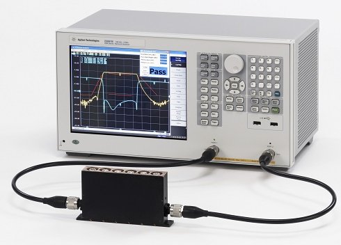
On a VNA, S21 reflects IL; S11/S22 depict match; S12 indicates isolation. Optimized ferrite geometry, narrow‑tolerance machining, and uniform magnetic bias can pull IL into the sub‑0.2 dB range for selected bands—while sustaining isolation, power handling, and temperature stability.
2) Why Low IL Isolators Win in the Real World
- Efficiency & EIRP: Less IL → more forward power reaches the antenna or the next active stage.
- Thermal Relief: Reduced dissipation shrinks heat load on chassis, enabling denser packaging.
- Noise‑Critical Chains: In receivers, IL contributes directly to system noise figure; shaving 0.1–0.2 dB matters.
- Linearity & Spectral Purity: Cooler, well‑matched chains improve ACLR/IMD behavior downstream.
- Lifetime & MTBF: Lower stress on PAs/LNAs and magnetics improves long‑term reliability.
Tips:
A common field lesson: if a transmitter is marginal on power/thermal budget, the quickest “free watt” often comes from reclaiming insertion loss across passives, starting with the isolator.
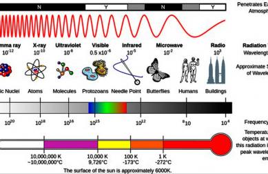
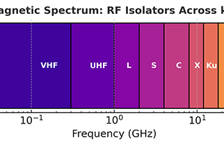
3) Application Lenses: From L-Band to Ka-Band
The need for low insertion loss strengthens as frequency climbs. Surface roughness, plating, mode conversion at transitions, and magnetization dispersion all tilt against you. That’s why engineers in L‑band navigation (1–2 GHz), X‑band radar (8–12 GHz), and Ka‑band SATCOM (26–40 GHz) scrutinize IL alongside isolation and VSWR.
| Band | Typical Frequency | Target IL (typ.) | Representative Systems |
|---|---|---|---|
| L‑Band | 1–2 GHz | ≤ 0.20–0.25 dB | GNSS, ATC, telemetry links |
| X‑Band | 8–12 GHz | ≤ 0.25–0.30 dB | Maritime/airborne radar, weather |
| Ka‑Band | 26–40 GHz | ≤ 0.30–0.40 dB | SATCOM gateways, 5G/Backhaul |
For program engineers, those numbers are not academic—they’re budget line items. Meeting link margin in the rain at Ka‑band, or preserving receiver sensitivity in congested X‑band harbors, starts with passives that don’t squander dB.
4) Design Trade‑Offs That Keep IL Low
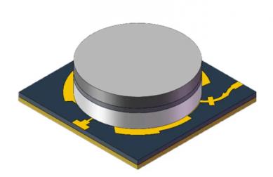
Ferrite & Bias: Garnet composition, saturation magnetization, linewidth, and temperature coefficients set a ceiling on what IL can be. A uniform, well‑shaped magnetic circuit is essential to avoid higher‑order mode conversion that masquerades as “mystery” loss.
Interfaces & Transitions: Whether coaxial (SMA/K/V), drop‑in microstrip, or waveguide, discontinuities are the thief of tenths of dB. Engineers look for controlled launch geometries, tight connector tolerances, and minimal step changes in impedance.
Conductor & Finish: Surface roughness and plating stack up at mmWave. High‑quality finish, proper thickness, and clean assembly clamp down conductor loss.
Thermal Path: Even “low‑loss” dissipates something. Direct thermal paths to chassis, matched CTE stacks, and power derating curves all help the isolator stay honest at temperature.
5) Measurement Discipline: Proving the Tenths
Engineers don’t trust claims—they trust setups. IL is verified with de‑embedded VNA fixtures, tight calibration (SOLT/TRL), and repeatable torque on connectors. At higher bands, fixture loss/phase must be taken out with diligence; otherwise, you are “measuring your cables.” Thermal soak and bias sweeps flush out drift that could widen IL in the field.
- Calibrate like you ship: identical cables/adapters, torque, and environment.
- Characterize over temperature: −40 °C to +85 °C for defense/industrial norms.
- Watch match: poor VSWR at either port adds effective loss and can stress PAs.
6) System Math: From dB to Decisions
Consider a radar transmitter delivering 200 W to the antenna. Dropping IL from 0.35 dB to 0.20 dB regains ~3.4% of forward power—seemingly small, yet it may be the difference between margin and miss in a tight EIRP budget. In receivers, 0.2 dB better IL can be almost a one‑for‑one win in noise figure upstream of the first active stage.
Decision pattern:
Teams that treat “sub-dB” as strategic usually ship cooler boxes, qualify smaller heat sinks, and unlock latitude for future waveform or PRF increases without re-spinning the thermal design.
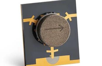
7) Packaging Paths: Pick the Right Form
No single package wins everywhere; the “lowest IL” lives where the mechanical and RF context agree:
- Drop‑In (Microstrip): The shortest path into a PCB can be the lowest‑loss path when launches are engineered. See HzBeat Drop‑In Isolators.
- Coaxial: Rugged, connectorized convenience with broad band options and excellent repeatability. See HzBeat Coaxial Isolators.
- Waveguide: At high power/mmWave, waveguide’s low conductor loss and mode control shine. See HzBeat Waveguide Isolators.
8) Reliability & Qualification: Low Loss That Stays Low
Engineers don’t only buy a spec; they buy its stability. Environmental cycling, vibration, and humidity can creep IL upward if magnetics or interfaces relax. That’s why serious programs call for screening to MIL‑STD‑202/‑810 practices, serialized S‑parameter data, and end‑of‑line thermal checks. HzBeat’s production flow bakes in these disciplines so that incoming IL matches the as‑designed target across life.
9) Total Cost of Ownership: The Cheapest Watt Is the One You Don’t Lose
IL savings compound: smaller power supplies, less copper in heat‑spreaders, fewer fans, quieter EMI, and a happier reliability engineer. In fielded fleets, even a fractional dB recovered across thousands of nodes becomes a line item worth fighting for.
10) How HzBeat Engineers for Low IL—Across 20 MHz to 200 GHz
- Advanced ferrite recipes and magnetic circuits to minimize dispersion loss.
- Precision CNC and surface finish control to curb conductor/surface roughness loss.
- Connector/launch libraries tuned by band for minimal discontinuity.
- Thermal architectures that keep bias uniform and IL tight under heat.
- OEM/ODM workflows—fast prototypes to flight‑grade builds.
Whether architecting an X‑band radar front‑end or a Ka‑band gateway, HzBeat delivers low‑insertion‑loss isolators that defend your margin without trading away isolation, power handling, or footprint.
Conclusion
Low‑insertion‑loss isolators are a lever on efficiency, stability, and lifetime. The right tenths of a dB, proven on a VNA and safeguarded in production, become design freedom across your roadmap. If your next radar, SATCOM, or 5G node needs those tenths back, start with the isolator—and choose one built to keep its promise.
FAQ
What exactly counts as “low insertion loss”?
≤0.3 dB is often considered low for microwave bands, tighter at L‑band and looser at Ka‑band.Will lowering IL reduce cooling needs?
Yes—less dissipated power eases thermal design, enabling smaller sinks or higher ambient headroom.Does low IL compromise isolation or power handling?
Not in a well‑engineered device that balances ferrite, bias, interfaces, and thermal paths.Which package gives the lowest IL?
Context‑dependent: PCB‑centric designs often favor drop‑in; ruggedized subsystems like coaxial; mmWave/high‑power prefer waveguide.Custom bands?
HzBeat offers OEM/ODM to tune IL to your band, geometry, interface, and qualification needs.References
- Microwave ferrite device design texts and IEEE MTT papers on isolator loss mechanisms and biasing.
- Peer‑reviewed studies on surface roughness effects and mmWave conductor loss.
- Program standards: MIL‑STD‑202/‑810 environmental screening practices.
- VNA calibration/application notes (TRL/SOLT) for de‑embedding fixture loss.
Explore HzBeat Solutions
- Drop‑In Isolators — PCB integration with engineered launches.
- Coaxial Isolators — connectorized, rugged, broadband options.
- Waveguide Isolators — low loss at power/mmWave.
Contact: [email protected]
Relateds

About the Author

HzBeat Editorial Content Team
Marketing Director, Chengdu Hertz Electronic Technology Co., Ltd. (Hzbeat)
Keith has over 18 years in the RF components industry, focusing on the intersection of technology, healthcare applications, and global market trends.