RF Circulator: Advantages and Disadvantages
RF circulator advantages and disadvantages explained in depth: isolation, insertion loss, bandwidth, temperature drift, biasing, validation, and how to choose the right RF circulator for radar, SATCOM, and 5G/6G.
The RF circulator is the quiet bodyguard of your front-end. Specify the right RF circulator and reflections vanish into a matched port, PAs keep linear, and duplex paths stay clean. Choose the wrong RF circulator and temperature drift, bandwidth edges, and IMD turn into hidden taxes on your link budget. This in-depth brief clarifies RF circulator advantages and disadvantages, showing how to maximize isolation and minimize insertion loss in real hardware.
RF Circulator Advantages
- Reverse isolation that saves hardware: An RF circulator typically offers 20–35 dB isolation (40 dB+ in tuned designs), dumping reflections safely to the third port and protecting PAs/LNAs.
- Low insertion loss where it matters: 0.2–0.6 dB in stripline/waveguide and 0.5–1.0 dB in SMT microstrip preserves system EIRP and receiver sensitivity.
- Power robustness: RF circulators in coaxial/waveguide handle hundreds of watts CW; miniaturized versions still manage tens of watts in compact modules.
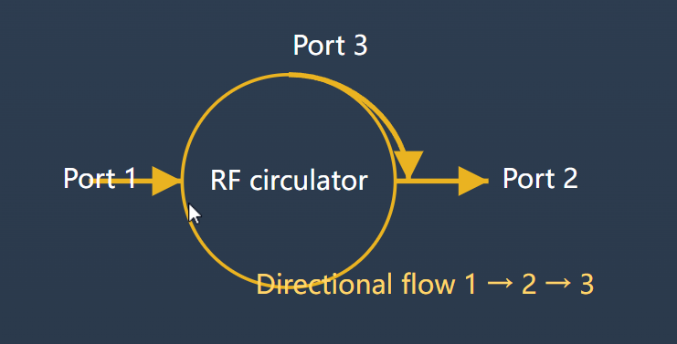
- True duplex enablement: The RF circulator simplifies TX–ANT–RX pathing, improving stability and reducing feedback-driven oscillations.
- Form-factor flexibility: Microstrip/SMT, drop-in/stripline, coaxial, and waveguide options match mechanical and thermal constraints.
- HzBeat strengths: Ultra-wideband coverage (20 MHz–200 GHz) and miniaturization deliver smaller, lighter RF circulators with competitive loss.
RF Circulator Disadvantages (Trade-offs to Manage)
- Bandwidth vs. loss: Wide fractional bandwidth pushes junction geometry and ferrite selection; otherwise isolation droops and loss rises at band edges.
- Temperature sensitivity: Ferrite properties shift with temperature; expect ΔIL/ΔT and ΔISO/ΔT. Thermal straps, magnet grade, and airflow paths matter.
- Biasing & magnetics: Permanent magnets or external bias add height and EMI concerns; keep ferromagnetics away from the RF circulator region.
- IMD & compression under drive: High flux density can produce intermod; validate with two-tone and modulated power, not just CW sweep.
- Low-band size/cost: Below ~300 MHz, ferrite volume and magnet mass increase; alternatives may win if power is modest.
How to Choose the Right RF Circulator
1) Electrical Targets
- Operating band and fractional bandwidth; define isolation floor and maximum insertion loss across the band.
- Return loss and VSWR; launcher and transition design dominate in SMT RF circulator layouts.
- Power rating (CW/peak) and IMD; check derating vs. temperature and frequency.
2) Mechanical & Thermal
- Package style (SMT/microstrip, drop-in, coaxial, waveguide) and mounting torque patterns.
- Magnet keep-out, shock/vibration, altitude/pressure; avoid placing sensors near the magnet of the RF circulator.
- Heat spreading under the junction; avoid hot-spots that shift bias field.
3) Validation Beyond the Datasheet
- VNA with SOLT/TTRL and fixture de-embedding; power-swept S-parameters over temperature.
- Two-tone IMD and ACPR under real modulations; measure isolation collapse at band edges.
- Environmental: vibe, shock, temp cycle, humidity/salt-fog for marine/aero programs.
Browse All Products Request a Custom RF Circulator
Spec Ranges (Quick Reference)
| Parameter | SMT / Microstrip | Drop-in / Stripline | Coaxial / Waveguide |
|---|---|---|---|
| Insertion Loss | 0.5–1.0 dB | 0.2–0.6 dB | 0.15–0.4 dB |
| Isolation | 18–28 dB | 22–38 dB | 25–45 dB |
| VSWR (max) | ≤1.7:1 | ≤1.45:1 | ≤1.3:1 |
| Power Handling | 5–40 W CW | 20–150 W CW | 100 W–kW CW |
| Temp Range | -20–+85 °C | -40–+95 °C | -40–+105 °C |
Applications Where an RF Circulator Excels
- Radar T/R modules: Duplexing and echo protection; see Selecting Ferrite Circulators for Radar Applications.
- 5G/6G base stations: Stability and linearity in massive MIMO arrays; RF circulator loss directly affects EIRP and coverage.
- Satellite links: Ground and payload duplexing; temperature swings stress the RF circulator — design for ΔT.
- MRI & industrial sensing: Isolating high-power RF pulses and protecting sensitive receive chains.
Related Reading (Internal News)
- Isolators vs. Circulators — Key Principles & Applications
- How to Design an RF Circulator – RF PCB Guide
- Can Miniaturized Circulators Handle High Frequencies?
- Optimize RF Chains Using High-Isolation Isolators
- The Origins and Evolution of the RF Circulator
- RF & Microwave Guide by HzBeat
Related Products (Deep Links)
Microstrip / SMT RF Circulators
Miniaturized RF circulator series for PCB modules; excellent size-to-loss balance and fast assembly.
Drop-in / Stripline RF Circulators
Low-loss RF circulator blocks for T/R boards; stable isolation over temperature with precise pocketing.
Coaxial RF Circulators
Medium-to-high power RF circulator solutions for rack systems and test stations.
Waveguide RF Circulators
High-power, low-loss RF circulator designs for SATCOM gateways and radar transmit chains.
RF Isolators (Companion Products)
One-way protection using the same ferrite physics; pair with an RF circulator when reverse isolation is the priority.
Browse All Series Get a Tailored Quote
Conclusion
The RF circulator is a precision compromise. Its advantages — isolation, stability, power headroom, and duplex simplicity — come with bandwidth, temperature, and magnetics trade-offs. Engineers who validate the RF circulator under power and temperature, and who integrate it carefully, win back link margin and reliability. With ultra-wideband coverage and miniaturization, HzBeat compresses loss and volume so your system performs where it counts.
FAQ
- Where is HzBeat based? Chengdu, China — serving radar, telecom, aerospace, and medical customers worldwide.
- Do you offer custom RF circulators? Yes. We tailor center frequency, bandwidth, footprint, power rating, and thermal design to your program.
- What sets HzBeat apart? Ultra-wideband coverage (20 MHz–200 GHz) and miniaturized structures, validated with power-swept, temperature-swept S-parameters.
References
- IEEE MTT tutorials and T-MTT papers on ferrite circulators (2022–2024).
- NASA/ESA notes on duplexing and non-reciprocal components in SATCOM payloads.
- HzBeat Product Catalog 2025 — https://www.hzbeat.com/product/

Sara
Sara is a Brand Specialist at Hzbeat, focusing on RF & microwave industry communications. She transforms complex technologies into accessible insights, helping global readers understand the value of circulators, isolators, and other key components.