Microstrip, Drop-in, Coaxial, or Waveguide: Choosing the Right RF Circulator Structure
A deep engineering guide to selecting the right RF Circulator structure—Microstrip Circulator, drop-in Circulator, Coaxial Circulator, or Waveguide Circulator—based on bandwidth, power handling, integration, thermal limits, and reliability.
Selecting the right RF Circulator structure is not a “catalog checkbox” decision. It is a system-level trade between bandwidth, insertion loss, isolation, thermal limits, mechanical integration, and power handling. This guide compares Microstrip Circulator, drop-in Circulator, Coaxial Circulator, and Waveguide Circulator designs with the kind of depth engineers actually need before committing to hardware.
1) What an RF Circulator really does
At a basic level, an RF Circulator is a passive non-reciprocal device that routes power from one port to the next in a fixed direction (for a 3-port: 1→2, 2→3, 3→1). The most common implementations use biased ferrite material to create non-reciprocity through gyromagnetic effects. That sounds academic—until you translate it into system behavior:
In a transmitter chain
Forward power control preserves the PA→antenna path, reflected power is routed away from the PA, and stability improves under load VSWR changes.
In a receiver or transceiver
Isolation reduces leakage, supports duplexing architectures, and improves measurement repeatability by taming reflections.
2) Why structure choice changes performance
Engineers often compare an RF Circulator by headline numbers: insertion loss (dB), isolation (dB), VSWR, power rating. Those matter—but the structure determines the physics behind those numbers, including what happens when your environment stops being “datasheet clean.”
The hidden variables: what datasheets don’t shout
- Thermal path: How heat flows out of the ferrite and conductors. This can dominate performance drift and long-term reliability.
- Field uniformity: Magnetic bias distribution impacts non-reciprocal behavior consistency across temperature and frequency.
- Conductor geometry & Q: Planar vs coax vs waveguide changes conductor loss, current density hotspots, and achievable low loss.
- Mechanical tolerance sensitivity: Some structures are forgiving; others turn tiny assembly variations into big RF shifts.
- Thermal path: Launch transitions (PCB-to-module, module-to-coax, coax-to-waveguide) can become the real bottleneck.
A practical perspective: the “system cost” of the wrong structure
The wrong choice rarely fails instantly. Instead, it bleeds performance: a few tenths of a dB extra loss here, a thermal drift there, unexpected ripple under high VSWR, or isolation that looks fine in the lab but collapses when the unit is bolted into a warm enclosure. That’s why structure selection is a system-level optimization.
3) Microstrip Circulator: planar integration when size is king
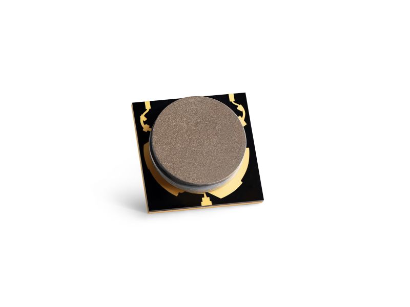
A Microstrip Circulator implements the non-reciprocal junction in a planar transmission line environment. It is attractive because it supports compact layouts, short interconnects, and scalable manufacturing. For phased array radar and dense RF front-ends, the Microstrip Circulator is often the only structure that fits the mechanical envelope.
3.1 Strengths of a Microstrip Circulator
- Footprint efficiency: Planar geometry enables miniaturization—critical for high-channel-count front-ends.
- Integration: Easy to integrate near MMICs, PA/LNA stages, or antenna feed networks with minimal connectors.
- Weight: Planar vs coax vs waveguide changes conductor loss, current density hotspots, and achievable low loss.
- Mechanical tolerance sensitivity: Favorable for airborne, space-constrained, and mobile platforms.
- Manufacturing scalability:Repeatable substrate processing can improve consistency at volume.
3.2 Trade-offs engineers must plan for
The biggest constraint is usually power handling and thermal extraction. Planar conductors can concentrate current density, and the thermal path often depends on substrate, ground vias, and mounting strategy. Under high duty cycle or poor heat sinking, insertion loss can drift, and isolation can degrade.
Bandwidth is also a nuanced topic: a Microstrip Circulator can be designed wideband, but the achievable fractional bandwidth depends on the junction design, ferrite properties, and matching network strategy. In many real products, you will see excellent performance over a targeted band rather than “anything goes” wideband.
Where Microstrip Circulator wins
- Phased-array T/R modules
- Compact SATCOM terminals
- Miniaturized 5G/6G radio units
- High-integration RF front-ends
Where it can bite you
- High average power with limited heat sink
- Severe mismatch conditions (high VSWR events)
- Mechanical environments requiring rugged connectorization
4) drop-in Circulator: the hybrid module-friendly sweet spot

A drop-in Circulator (often stripline-based) sits between planar and connectorized worlds. It typically lives inside a metallic housing, with RF transitions designed to mate with a system PCB or module cavity. This structure is popular when you need stronger mechanical stability and better shielding than a pure planar Microstrip Circulator, but you still want a compact integration style.
4.1 Why drop-in Circulator remains relevant
“Drop-in” sounds old-school, but it’s a practical engineering answer to a modern problem: dense RF modules that must survive real conditions. The housing improves shielding and can provide a more repeatable electromagnetic boundary, which helps isolation consistency. Thermal conduction can also be better than a purely planar build—depending on how it is mounted.
4.2 Typical strengths
- Mechanical and RF repeatability: Housing constraints stabilize performance across assemblies.
- Integration flexibility: Works in custom RF modules and multi-layer assemblies without external connectors.
- Balanced performance: Often achieves a practical compromise of low loss, good isolation, and moderate bandwidth.
4.3 Common trade-offs
The integration is not plug-and-play. You must design the surrounding transitions and ground interface correctly. If the module cavity is poorly designed, you can introduce resonances, mismatch, or coupling that undermines the circulator. In other words: the drop-in Circulator is excellent, but it expects you to respect RF packaging.
5) Coaxial Circulator: wideband ruggedness with connector convenience
The Coaxial Circulator is the everyday hero of RF systems: connectorized, robust, and often available across broad frequency ranges. Its geometry supports practical heat paths and mechanical strength, making it a common choice for PA protection, EW subsystems, communication infrastructure, and lab equipment.
5.1 Where Coaxial Circulator shines
- Wideband practicality: Many Coaxial Circulator designs support useful fractional bandwidth with stable match.
- Ease of integration: Standard connectors reduce integration risk and accelerate prototyping.
- Serviceability: Replacement and debugging are easier compared with deeply embedded modules.
- Rugged mechanical behavior: Better suited for vibration, handling, and field maintenance.
5.2 The real engineering trade
Size and connector physics are the tax. The Coaxial Circulator is bigger than a Microstrip Circulator or drop-in Circulator, and at very high frequencies the connector interface can become a limiting factor. For dense arrays or high channel count designs, coaxial units may become mechanically impractical.
5.3 When Coaxial Circulator is the safest decision
If you are building a system where you cannot afford integration surprises—especially during early prototypes—starting with a Coaxial Circulator often reduces risk. You can validate your power, mismatch behavior, and stability first, and then consider migration to drop-in Circulator or Microstrip Circulator forms if the program later demands miniaturization.
6) Waveguide Circulator: high power, low loss, serious microwave territory
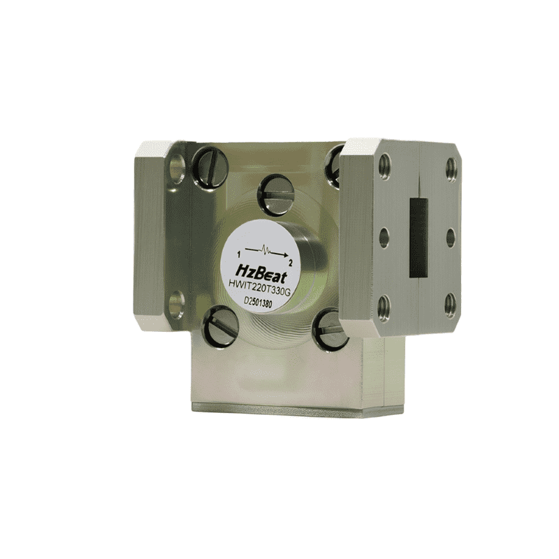
If the phrase “high power” is written in bold on your system requirement, the Waveguide Circulator deserves your attention. Waveguide structures can handle high peak and average power because the electromagnetic field distribution and conductor geometry reduce current density hotspots compared with compact planar lines. Thermal management is typically superior, and insertion loss can be very low.
6.1 Why Waveguide Circulator dominates high power systems
- Power handling: Often the best choice for high average power and high peak power microwave transmit chains.
- Low insertion loss: Waveguide conductors support low loss across defined bands.
- Thermal resilience: More metal mass and better conduction paths reduce thermal drift and stress.
- Reliability: Frequently selected for radar, ground station SATCOM, and demanding industrial microwave platforms.
6.2 The trade-offs you cannot ignore
The Waveguide Circulator is larger, heavier, and often more expensive. It also tends to be band-specific because waveguide dimensions are tied to frequency bands. If you need ultra-compact integration, waveguide is usually not your friend. But if you need an RF Circulator that behaves predictably under high duty cycle and high VSWR events, waveguide may be the only structure that offers comfortable margin.
7) Comparison table & a selection workflow that actually works
Let’s put the four options—Microstrip Circulator, drop-in Circulator, Coaxial Circulator, and Waveguide Circulator—into a side-by-side engineering context. The table below focuses on the “decision drivers” that most strongly impact system success.
| Structure | Integration Style | Typical Strength | Typical Constraint | Best-fit Use Cases | Selection Notes |
|---|---|---|---|---|---|
| Microstrip Circulator | Planar / PCB-level | Miniaturization, high integration | Thermal & power limits; packaging sensitivity | Phased arrays, compact radios, dense front-ends | Design thermal path + transitions as part of the RF Circulator choice |
| drop-in Circulator | Hybrid module / cavity mount | Stable shielding, compact robustness | Requires careful mechanical/RF integration | Custom RF modules, aerospace/mil subsystems | Great compromise when connectorized size is unacceptable |
| Coaxial Circulator | Connectorized coax | Wideband practicality, ruggedness | Size/weight; connector limitations at very high freq | PA protection, lab test, field systems | Often best for prototypes and wideband architectures |
| Waveguide Circulator | Waveguide flange | High power + low loss + thermal margin | Large, heavier, band-specific, higher cost | Radar transmitters, ground stations, high-power microwave | Choose when power/thermal reliability is the top priority |
7.1 A simple selection workflow (start with constraints, not preferences)
Step 1: Power & duty cycle
- If high average power or high peak power: prioritize Waveguide Circulator, then Coaxial Circulator.
- If moderate power with compact package: consider drop-in Circulator.
- If low/moderate power and high integration: consider Microstrip Circulator.
Step 2: Integration & volume
- If PCB-level integration is mandatory: Microstrip Circulator.
- If you can design a cavity/module: drop-in Circulator.
- If connectors are acceptable and speed matters: Coaxial Circulator.
- If waveguide chain exists: Waveguide Circulator.
7.2 Where HzBeat-style priorities fit (wideband + miniaturization)
If your product strategy values ultra-wideband coverage and miniaturization, structure choice becomes a portfolio strategy: you may offer a Microstrip Circulator or drop-in Circulator line for compact RF front-ends, while maintaining a Coaxial Circulator line for wideband rugged deployments, and a Waveguide Circulator line for high-power microwave users. The “right” RF Circulator structure can differ by customer segment even for the same frequency band.
8) Design checklist: what to specify and why
When you ask a supplier for an RF Circulator, structure is only the first decision. To avoid the classic “it looked fine on paper” trap, specify the parameters that control real-world behavior—especially for Microstrip Circulator and drop-in Circulator designs, where integration details can dominate performance.
8.1 Electrical requirements
- Frequency range and bandwidth: State the band and any critical sub-bands. Wideband claims should be validated with full curves.
- Insertion loss: Provide a maximum and (if possible) a typical target. Also state acceptable ripple.
- Isolation: Define minimum isolation across band and temperature. Isolation is often the first spec to degrade under stress.
- VSWR / Return loss: Specify both input and output match requirements if your architecture is sensitive.
- Power handling: Separate peak and average power. Duty cycle matters. Also clarify mismatch conditions (e.g., VSWR 2:1, 3:1, etc.).
8.2 Thermal and environmental requirements
- Operating temperature range: Define the true environment (enclosure temps can exceed ambient).
- Thermal interface: Especially for Microstrip Circulator and drop-in Circulator, specify mounting and heat sinking assumptions.
- Vibration and shock: If relevant, connectorized Coaxial Circulator may be preferred over fragile integration styles.
8.3 Integration details (often the real performance limiter)
- Port definition: Confirm directionality markings and port mapping (the “1→2” reality must match your system layout).
- Connector type (for Coaxial Circulator): SMA, N, 2.92mm, etc., with torque and mechanical constraints.
- Waveguide type (for Waveguide Circulator): WR sizes, flange types, surface finish, and alignment requirements.
- Grounding strategy: For drop-in Circulator, define how it is bonded to the chassis and how RF currents return.
If you want fewer surprises: Prototype with a Coaxial Circulator when possible, validate mismatch and thermal behavior, then migrate to drop-in Circulator or Microstrip Circulator for miniaturization—unless the final system will be waveguide-based, in which case start with a Waveguide Circulator early and design the mechanical chain around it.
9) Summary
Choosing an RF Circulator structure is a decision about physics, packaging, and reliability—not just a part number. The Microstrip Circulator is the champion of integration and compactness, ideal for dense RF front-ends and phased arrays. The drop-in Circulator offers a highly practical middle ground for custom modules where you want compact robustness and stable shielding. The Coaxial Circulator is the rugged, wideband, connector-friendly workhorse that reduces integration risk and accelerates development. The Waveguide Circulator dominates high-power microwave environments where low loss and thermal margin drive system survivability.
If your brand or product roadmap emphasizes wideband coverage and miniaturization, treat structure selection as a portfolio: different customers need different “best” answers. In the end, the right RF Circulator structure is the one that meets your specs with comfortable thermal and reliability margin—because RF power always tells the truth eventually.
10) FAQ
Which structure gives the best insertion loss: Microstrip, drop-in, Coaxial, or Waveguide?
In many high-power microwave bands, a Waveguide Circulator tends to achieve very low insertion loss thanks to waveguide conductor geometry and strong thermal margin. A well-designed Coaxial Circulator can also be low-loss and very practical. A Microstrip Circulator can be low-loss for compact bands, but planar losses and thermal effects become more visible as power and frequency climb.
Is a Coaxial Circulator always wider band than a Microstrip Circulator?
Not always, but in many real products a Coaxial Circulator provides a more forgiving wideband solution because the geometry supports robust matching and packaging stability. A Microstrip Circulator can be designed wideband, but integration details and planar constraints often push designs toward optimized band ranges rather than “maximum possible” fractional bandwidth.
When should I choose a drop-in Circulator instead of a Microstrip Circulator?
Choose a drop-in Circulator when you need compactness but also want the mechanical stability and shielding benefits of a housed module, especially in custom RF assemblies. If your PCB environment is thermally limited or mechanically harsh, a drop-in Circulator often offers a safer margin than a purely planar Microstrip Circulator.
Why do Waveguide Circulators feel “band-limited”?
Waveguide dimensions scale with wavelength, and waveguide components are typically optimized for a waveguide band (e.g., WR sizes). That makes a Waveguide Circulator extremely strong inside its band, but less flexible across very wide frequency spans compared with some Coaxial Circulator approaches.
What should I ask a supplier to reduce integration risk?
Request full S-parameter data across frequency and temperature, clarify power definitions (average vs peak), specify mismatch conditions, confirm port mapping and directionality, and—if selecting Microstrip Circulator or drop-in Circulator—share your mechanical/thermal mounting assumptions early.
11) References
- D. M. Pozar, Microwave Engineering, 4th ed., Wiley. (Foundational coverage of microwave networks, S-parameters, and passive component behavior.)
- R. E. Collin, Foundations for Microwave Engineering, 2nd ed., Wiley-IEEE Press. (Background on wave propagation and microwave component principles.)
- IEEE Microwave Theory and Techniques Society resources on ferrite and non-reciprocal devices (general technical background and terminology standardization).
- M. L. Bozzi et al., literature on non-reciprocal ferrite devices and practical implementations in microwave systems (conceptual grounding for structure-dependent trade-offs).
- Manufacturer application notes on circulator/isolator selection (integration and mismatch considerations; compare structure-dependent thermal and packaging effects).
Recommended Products
.jpg)


Keith Wong
Marketing Director, Chengdu Hertz Electronic Technology Co., Ltd. (Hzbeat)
Keith has over 18 years in the RF components industry, focusing on the intersection of technology, healthcare applications, and global market trends.