Dual-Junction RF Circulator: Principle and Types
Explore the principle and main types of dual-junction RF circulators including T-type, Y-type, and structural variations. Learn how these configurations enhance isolation, reduce VSWR, and improve power stability in modern microwave systems.
Introduction
Dual-junction RF circulators connect two ferrite junctions in series to achieve stronger non-reciprocity, higher isolation, and better tolerance to mismatch than a single-junction device. They are a pragmatic way to keep transmitters safe from reflected power while holding insertion loss and VSWR to tight budgets in base stations, phased-array radar, satcom terminals, and test systems.
Two Topologies at a Glance
- T-Type: Tx–Rx arranged linearly; antenna at one end; a matched resistor terminates the isolation port.
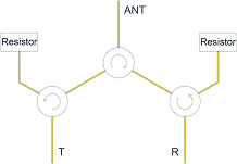
- Y-Type: Star-like split; antenna at the top; both isolation ports are resistively terminated.
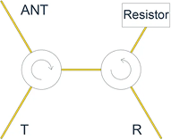
T-Type Dual-Junction Circulator
The T-type places the antenna and the two active junctions along a single path. The isolation port is resistively terminated so that reflected energy from the antenna is absorbed rather than re-entering the transmitter. This geometry is common in compact radios where the RF chain is arranged end-to-end on a microstrip or stripline layout.
When it shines
- Space-constrained layouts and low BOM count.
- Systems prioritizing lowest insertion loss between Tx and ANT.
- Moderate bandwidth with predictable biasing and simple thermal path.
Things to watch
- Asymmetry can make Rx protection slightly less forgiving under severe antenna detuning.
- Thermal hotspot near the termination if antenna mismatch is frequent.
Y-Type Dual-Junction Circulator
The Y-type forms a three-way node: the antenna sits at the top branch while transmitter and receiver occupy the lower branches. Each isolation path ends with a matched load. The symmetry helps maintain balance over wider bandwidths and reduces sensitivity to PCB tolerances.
Where it excels
- Wider bandwidth or multi-band operation with better port-to-port balance.
- Arrays and TDD systems that encounter fast-changing VSWR conditions.
- Thermal spreading thanks to two smaller terminations instead of one hot load.
Design cautions
- Slightly higher insertion loss compared to a well-tuned T-type.
- More complex routing and matching at the central node.
Types of Dual-Junction Circulators by Structure
Beyond topology (T-type vs Y-type), dual-junction circulators are delivered in multiple structural implementations to fit different power, bandwidth, and integration needs.
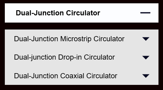
Microstrip (PCB / SMD)
- Best for: compact radios, modules, and arrays where size and cost matter.
- Pros: smallest footprint, easy routing, good for multi-channel layouts.
- Limits: lower power than drop-in/coaxial; board stack-up strongly affects bandwidth.
Drop-in
- Best for: medium-to-high power transmitters and wideband front-ends.
- Pros: robust ferrite block with controlled cavity; solid thermal path; stable over temperature.
- Limits: larger height and mechanical integration required (milled pockets or carriers).
Coaxial
- Best for: lab/test gear, SATCOM feed chains, or systems using coax interconnects.
- Pros: convenient connectors, excellent shielding, easy to swap and test.
- Limits: largest volume and weight; transitions add insertion loss in densely integrated radios.
Performance & Design Trade-offs
- Isolation: dual-junction adds 10–20 dB isolation headroom over a comparable single-junction, depending on ferrite material, bias, and matching.
- Insertion loss: keep total below the link-budget threshold—use low-loss ceramics, short transitions, and tight tolerance magnets.
- VSWR: a balanced layout and accurate 50-Ω terminations keep port VSWR low and protect power amplifiers.
- Power & thermal: size the resistor(s) for mismatch power. In Y-type, two resistors share dissipation; in T-type, plan a heat path for the single load.
- Form factor: microstrip/stripline for compact radios; drop-in or waveguide for higher power.
Selection Checklist
- Band: L/S/C/X/Ku/Ka; target fractional bandwidth
- Power: CW and peak; mismatch survival
- Loss/ISO: Max IL, min isolation, VSWR
- Size: Microstrip, drop-in, coaxial, or waveguide
- Thermal: Termination wattage & heat spread
- Reliability: Temp drift, magnet aging, shock/vibe
Test & Verification
- Use a calibrated VNA (TRL/SOLT) with suitable fixtures; de-embed adapters.
- Measure S21 (Tx→ANT), S32 (ANT→Rx), and isolation S13/S31 across temperature.
- Mismatch testing: sweep antenna VSWR 1.2–3.0 and record power dissipation at terminations.
- Thermal soak and shock to verify magnet stability and bias circuitry.
FAQ
Is a dual-junction always better than a single-junction?
No. If your band is narrow and the antenna is well matched, a quality single-junction may meet targets with lower cost. Dual-junction adds margin for tough VSWR and wider bandwidths.
Which topology should I start with?
Choose T-type for lowest path loss and simple routing; choose Y-type for symmetry, bandwidth, and thermal sharing.
How do I size the resistive terminations?
Estimate worst-case reflected power (PA power × reflection coefficient) and add 2× safety. In Y-type, split the dissipation between two loads.
References
- Pozar, D. M. Microwave Engineering, 4th ed.
- Collin, R. E. Foundations for Microwave Engineering.
- Manufacturer app notes on ferrite circulators and biasing best practices.
© HzBeat · Dual-Junction RF Circulators

Keith Wong
Marketing Director, Chengdu Hertz Electronic Technology Co., Ltd. (Hzbeat)
Keith has over 18 years in the RF components industry, focusing on the intersection of technology, healthcare applications, and global market trends.