Why 6–18 GHz Is the Golden Frequency Range for C, X & Ku Band RF Circulators
A comprehensive technical deep dive into why 6–18 GHz—covering C Band, X Band, and Ku Band—has become the golden frequency range for broadband RF and microstrip circulators, with real product evidence from HzBeat.
Introduction: From Narrowband Thinking to Wideband RF Architecture
For decades, RF front-end design was dominated by narrowband assumptions. A system had a primary frequency plan, a fixed antenna environment, and a predictable load. RF circulators were therefore treated as frequency-specific components—picked for a center frequency and then “left alone.”
Today, that model is increasingly unrealistic. Radar platforms switch modes. SATCOM terminals face changing antenna conditions. Test and measurement systems sweep continuously. Even embedded RF modules are expected to support multiple bands over a long product lifecycle. In this new reality, the RF circulator becomes less of a “protection accessory” and more of a system stability device—especially when wide bandwidth is involved.
Among all practical microwave ranges, 6–18 GHz stands out. It unifies C Band, X Band, and Ku Band into a single continuous window. This is why engineers increasingly treat 6–18 GHz as the golden frequency range for broadband RF circulators and broadband microstrip circulators.
The Expanding Role of RF Circulators in Wideband Systems
From “Component Spec” to “System Behavior Control”
An RF circulator is a non-reciprocal, three-port passive device that routes power sequentially from port to port. When the third port is terminated, it functions as an RF isolator, absorbing reflections rather than allowing them to stress upstream stages. Classic microwave engineering texts emphasize that reflection behavior and mismatch are not edge cases—they are part of real-world RF life. As bandwidth expands, the probability of encountering frequency-dependent mismatch increases.
Why Reflections Become More Dangerous in Broadband Operation
Broadband architectures must tolerate wide variations in antenna impedance, connector transitions, cable assemblies, and environmental changes. A mismatch that is “acceptable” at one frequency may become significant at another. In power amplifiers, that can translate to increased heat, compression, spectral regrowth, or long-term reliability concerns. In receivers, reflections can create ripple, instability, or calibration drift. A broadband RF circulator reduces the system’s sensitivity to these variations by forcing energy to follow a controlled path.
Why Microstrip Form Factor Matters for Modern RF Front Ends
The move toward compact modules and high channel density makes planar integration attractive. A broadband microstrip circulator is often easier to place near the critical boundary—close to the PA, LNA, or antenna port— reducing interconnect length and limiting parasitic uncertainty. In many modern designs, placement and integration quality become as important as the headline numbers.
Why C Band, X Band, and Ku Band Are Converging
C Band Circulators: The Foundation of Wideband RF Systems
C Band is widely used across radar and satellite links, offering a strong balance between propagation and bandwidth. But in many platforms, C Band is no longer the “end of the story.” Once a system supports wideband operation, the architectural push is often upward: higher resolution radar modes, higher throughput links, or expanded sensing capability. A broadband approach that spans C Band into the upper bands reduces the need for band-specific hardware.
For related selection context, teams often build a cluster page such as C Band circulator selection guide.
X Band Circulators: The Core of Radar and Sensing Platforms
X Band remains a major center of gravity for radar and sensing because it balances antenna size, atmospheric behavior, and resolution. However, X Band front ends are also more sensitive to mismatch and packaging discontinuities than lower microwave bands. When a platform runs multiple radar waveforms or modes, a broadband RF circulator helps keep the RF chain behavior consistent while switching frequencies.
Ku Band Circulators: Bandwidth Meets Sensitivity
Ku Band is central to SATCOM and high-resolution radar. It also compresses the tolerance window: small transitions, minor assembly variation, or frequency-dependent impedance shifts can produce outsized effects. This is exactly where a 6–18 GHz broadband microstrip circulator provides system value—not by being “perfect” at one point, but by keeping performance predictable across Ku Band while still supporting X Band and upper C Band.
For SATCOM-driven programs, internal linking to Ku Band circulators in satellite communication helps capture long-tail intent while strengthening the pillar page.
The Limitations of Narrowband Circulator Strategies
The Hidden Cost: Complexity Multiplies Faster Than Performance
A common legacy strategy is to deploy multiple narrowband circulators—one for C Band, one for X Band, and one for Ku Band. On paper, this looks attractive: each part can be optimized for its band. In practice, system complexity grows rapidly: more components, more transitions, more interconnects, more places for mismatch to accumulate. Each additional interface is an opportunity for ripple, loss, or unexpected coupling.
Insertion Loss and Mismatch Accumulation
Even if each narrowband RF circulator has strong specs, the total chain is what matters. RF loss is cumulative. Return loss interactions can create standing-wave ripple. Switching networks add additional discontinuities. Over a wide band, these effects rarely average out—they often show up as unpredictable variation in system performance.
Operational Risk: Frequency Switching and Field Variability
Modern systems do not live in ideal laboratory environments. Temperature shifts, connector wear, cable assemblies, and antenna conditions change. A narrowband approach is more likely to behave “great at the center” but drift at band edges or under real-world variation. Broadband architectures reduce operational risk by choosing consistency and predictability over single-point peak optimization.
6–18 GHz as the Natural Operating Sweet Spot
A Band Where Broadband Makes Sense Architecturally
6–18 GHz is a unique window in system planning. It bridges multiple high-value bands that commonly appear together in modern RF roadmaps. A single broadband RF circulator covering this range can support: multi-mode radar operation, mixed-band SATCOM payload needs, and wideband sweep test platforms. That cross-application demand is one reason the band is “golden.”
A Band Where Broadband Remains Practical Physically
Above this range, parasitic sensitivity becomes harsher, and mechanical tolerances demand even tighter control. Below this range, system drivers may differ, and component choices broaden (sometimes pushing toward other architectures). At 6–18 GHz, ferrite-based non-reciprocal behavior remains practical while planar integration remains feasible. This is where broadband microstrip circulators offer a compelling balance of size, manufacturability, and controlled performance.
Why “Balanced Parameters” Win in Wideband Design
Wideband design is not about chasing a single extreme metric. It is about maintaining acceptable insertion loss, isolation, and VSWR across the band, so system performance is stable as frequency changes. This is also why engineering teams evaluate a broadband RF circulator by system outcomes—PA protection margin, receiver stability, and measurement repeatability—rather than one isolated data point.
Broadband Microstrip Circulators in Practice: HzBeat’s 6–18 GHz Solution
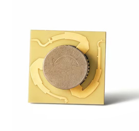
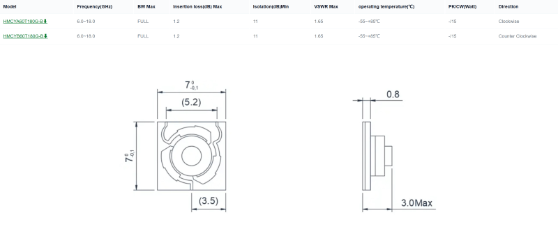
HzBeat’s 6–18 GHz broadband microstrip circulator demonstrates what a “golden band” product looks like in practice: compact integration, predictable wideband behavior, and practical system-level performance targets. For broader families and formats, see the main hub: RF Circulators.
What the Specification Table Really Tells System Engineers
A wideband RF circulator’s specs should be read as a “system behavior promise.” FULL-band coverage indicates the circulator is intended to remain usable across C Band, X Band, and Ku Band rather than being tuned for a single center. Insertion loss maximum values define how much link budget impact to expect. Isolation minimum values define a baseline for reflection management. VSWR maximum provides a boundary on mismatch behavior across the band.
Clockwise vs. Counter-Clockwise: Why Direction Options Matter
Direction is not a cosmetic feature. In dense layouts, the ability to choose clockwise and counter-clockwise flow reduces routing contortions, supports cleaner transitions, and improves system integration.
Where to Use Microstrip vs. Coaxial vs. Waveguide
Microstrip circulators are ideal when integration density and module-level compactness matter most. If power or mechanical constraints dominate, consider format alternatives: Coaxial Circulators and Waveguide Circulators. This mixed-format perspective helps teams select the right RF circulator architecture for each subsystem.
System-Level Advantages Enabled by the 6–18 GHz Range
1) One Wideband Device Across C, X, and Ku
A single 6–18 GHz broadband RF circulator can reduce the number of band-specific parts. That simplifies BOM, layout, qualification testing, and future upgrades. For teams building wideband front ends, that simplification often translates into faster iteration cycles and fewer integration surprises.
2) Stable Behavior Under Mismatch and Load Variation
Mismatch is not an “if,” it is a “when.” Antenna environments change. Test fixtures vary. Cables move. Broadband circulators reduce sensitivity by controlling where reflected energy goes, protecting upstream stages and improving stability. When used as an RF isolator (with a terminated port), the benefit becomes even more explicit at the system boundary.
3) Higher Integration Density, Shorter RF Paths
In 6–18 GHz systems, every millimeter of interconnect can matter. Shorter routing reduces parasitic uncertainty and improves repeatability. This is where a broadband microstrip circulator’s compact footprint and planar integration deliver real advantages. To explore microstrip families, link out to: Microstrip Circulators.
4) Future-Ready RF Architecture
When a platform’s frequency plan evolves, a wideband RF circulator reduces redesign pressure. Instead of swapping parts for each band expansion, teams can maintain the core front-end stability device and iterate on adjacent blocks. This is a practical reason 6–18 GHz is viewed as a golden range: it aligns with real product roadmaps.
Conclusion
6–18 GHz is the golden frequency range for broadband RF circulators because it aligns with the modern reality of RF systems: C Band, X Band, and Ku Band increasingly appear together in real architectures, and wideband stability matters more than ever.
A broadband microstrip circulator covering 6–18 GHz simplifies system design, improves front-end robustness, and supports higher integration density. For product families and formats, visit: HzBeat RF Circulators. If you want engineering support for your specific system constraints, a lightweight next step is to contact HzBeat engineering team.
FAQ
Why is 6–18 GHz preferred over higher millimeter-wave bands for broadband microstrip circulators?
As frequency increases, planar integration becomes more sensitive to parasitic effects and manufacturing tolerances. 6–18 GHz offers a practical balance: wide enough to unify C/X/Ku bands, yet still manufacturable and integrable at module level.
Can a broadband RF circulator replace multiple narrowband C Band, X Band, and Ku Band circulators?
In many architectures, yes. A 6–18 GHz broadband RF circulator reduces part count and routing complexity, which often improves overall system repeatability. However, extreme narrowband peak-performance requirements may still justify specialized band-specific parts.
When should a coaxial or waveguide circulator be considered instead of a microstrip circulator?
If power handling, mechanical constraints, or environmental conditions dominate, consider coaxial circulators or waveguide circulators. Microstrip circulators excel where compactness and integration density are primary requirements.
References
- David M. Pozar, Microwave Engineering, Wiley.
- R. E. Collin, Foundations for Microwave Engineering, Wiley.
- J. Helszajn, Nonreciprocal Microwave Junctions and Circulators, Wiley.
- IEEE Microwave Theory and Techniques Society (MTT-S) publications and application papers on ferrite circulators and non-reciprocal junctions.
Recommended Products

.jpg)


Keith Wong
Marketing Director, Chengdu Hertz Electronic Technology Co., Ltd. (Hzbeat)
Keith has over 18 years in the RF components industry, focusing on the intersection of technology, healthcare applications, and global market trends.