How Do RF Circulators Direct Signal Flow in RF Systems
Learn how an RF circulator directs signal flow in RF systems, manages reflected power, improves isolation, and supports radar, communication, and amplifier protection applications.
In modern RF systems, signal transmission is not only about sending power from one point to another. Engineers must also control where the energy goes, where reflected power ends up, and how sensitive circuits are protected from unwanted reverse energy. This is where the RF circulator becomes essential. Rather than acting like a simple connector or passive pass-through device, it creates a defined directional path for microwave energy and helps maintain order inside complex signal chains.
An RF circulator is widely used in radar platforms, communication links, transceiver modules, and amplifier protection networks because it can direct signal flow in a controlled and repeatable way. In practice, it helps separate transmit and receive paths, route reflected energy away from critical stages, and improve the overall stability of high-frequency systems.
1. What Is an RF Circulator?
1.1 Basic Definition
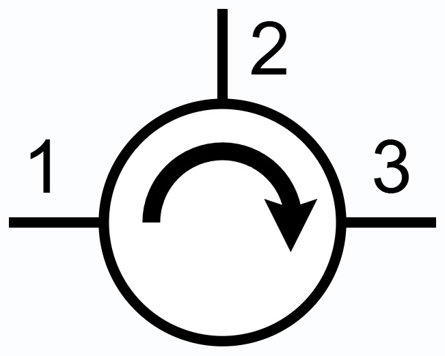
An RF circulator is a non-reciprocal passive component, most commonly built as a three-port device. Its job is to guide microwave energy from one port to the next in a fixed sequence. In a typical three-port design, energy entering Port 1 exits mainly through Port 2, energy entering Port 2 exits mainly through Port 3, and energy entering Port 3 exits mainly through Port 1.
1.2 Why It Is Called Non-Reciprocal
In reciprocal components, transmission from Port A to Port B is essentially the same as from Port B to Port A. An RF circulator does not behave that way. It breaks symmetry and gives each signal path a preferred direction. This is why RF circulators are important in RF systems that require controlled signal flow rather than simple bidirectional connectivity.
1.3 Difference Between a Circulator and an Isolator
A circulator and an isolator are closely related. If one port of a circulator is terminated with a matched load, reflected energy can be absorbed at that port instead of returning to the source. In that configuration, the circulator effectively behaves like an isolator.
2. Why Signal Direction Matters in RF Systems
2.1 Reverse Energy Can Damage Performance
In real RF systems, energy does not always move neatly in the forward direction. Mismatch at the antenna, connector tolerances, thermal drift, and varying load conditions can create reflected power. If that reflected power returns directly to the source or amplifier stage, it can reduce efficiency, disturb linearity, and create instability.
2.2 Shared-Antenna Architectures Need Routing Control
Many radar and communication systems use a shared antenna for both transmitting and receiving. This improves integration and reduces system size, but it also creates a routing challenge. High-power transmit energy must not leak directly into the receive path. An RF circulator helps solve this by directing forward transmit energy toward the antenna while guiding received energy toward the receiver chain.
3. How RF Circulators Direct Signal Flow
3.1 The Three-Port Operating Principle
The most common RF circulator is the three-port type. In a clockwise or counterclockwise sequence, each port sends energy mainly to the next port in line. This defined sequence creates a directional route for signal flow.
3.2 Forward Routing Instead of Random Energy Distribution
An RF circulator does not make energy disappear, and it does not produce perfect one-way transmission under every condition. What it does is establish a preferred low-loss path and a relatively suppressed unwanted path.
3.3 Signal Flow in a Typical Transmit-Receive Chain
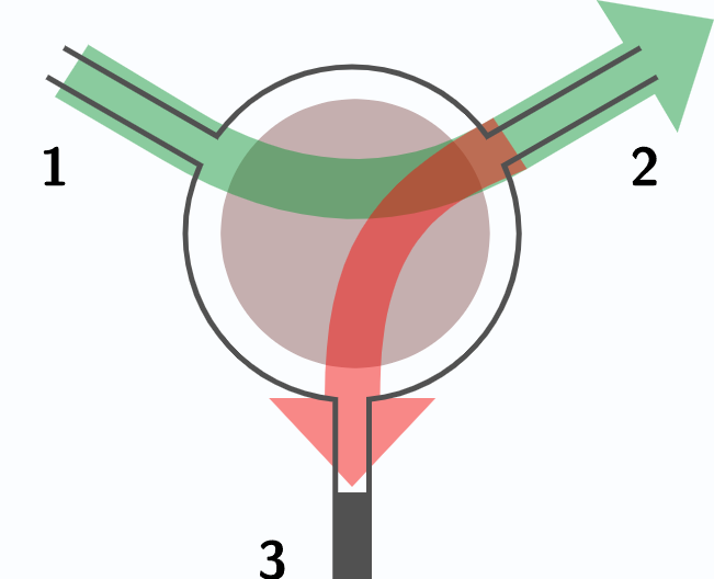
Imagine Port 1 connected to a transmitter, Port 2 connected to an antenna, and Port 3 connected to a receiver. The transmitted signal flows mainly from Port 1 to Port 2. A received signal coming back from the antenna flows mainly from Port 2 to Port 3.
4. The Physics Behind RF Circulators
4.1 Ferrite Materials Make Non-Reciprocal Operation Possible
Most traditional RF circulators rely on ferrite materials. Ferrites are useful because they can exhibit gyromagnetic behavior under an external magnetic field. This allows electromagnetic waves to experience different conditions depending on propagation direction.
4.2 External Magnetic Bias Is Critical
The magnetic bias is not just a supporting feature. It is part of what makes an RF circulator work. Without the magnetic field, the device cannot maintain the same directional transmission behavior.
4.3 Practical Performance Is Always a Design Balance
Real devices involve trade-offs. Material losses, matching conditions, geometry, thermal stability, bandwidth requirements, and power handling all influence how well a circulator maintains directional signal flow in RF systems.
5. RF Circulators in Real RF Systems
5.1 Radar Systems
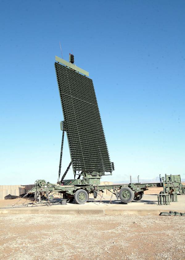
In radar, RF circulators are used to separate transmit and receive paths while allowing the use of a shared antenna. During transmission, the high-power pulse is directed toward the antenna. During reception, return signals are guided toward the receiver chain.
5.2 Communication Systems
In communication RF systems, circulators can improve path isolation, support shared hardware, and help manage reflected power. They are useful in base station and microwave link environments where signal integrity and front-end reliability are critical.
5.3 Transceiver Modules
Compact transceiver modules often require tight integration and careful control of internal signal flow. An RF circulator helps route energy between amplifier stages, antenna interfaces, and receiver sections without requiring excessive additional circuitry.
5.4 Amplifier Protection Networks
Power amplifiers are vulnerable to reflected energy. An RF circulator can redirect that reflected power to another port, where it can be absorbed or monitored instead of being sent back into the amplifier.
6. How Reflected Power Is Managed
6.1 What Happens During Mismatch
When the load or antenna is not perfectly matched, some portion of the forward energy reflects back. In a system without directional control, that energy may return directly to the source. In a system using an RF circulator, the reflected energy can be routed to the next port in sequence instead.
6.2 Redirecting Reflections Away from the Source
This is one of the most valuable functions of RF circulators. Instead of allowing reflected energy to strike sensitive stages head-on, the circulator redirects it into a more manageable path.
7. Key Parameters That Affect Signal Flow
7.1 Insertion Loss
Insertion loss describes how much signal power is lost along the intended transmission path. Lower insertion loss means more efficient signal flow and better overall RF system performance.
7.2 Isolation
Isolation describes how strongly the unwanted path is suppressed. High isolation means the RF circulator is better at preventing energy from reaching the wrong port.
7.3 VSWR and Matching
Matching strongly affects how well the circulator performs inside the complete RF system. Poor matching increases reflections, disturbs signal flow, and can make even a good device look bad in practice.
7.4 Bandwidth
Wider bandwidth is often harder to achieve while maintaining low insertion loss, high isolation, and good matching.
7.5 Power Handling
Different RF circulator structures support different power levels. Power handling depends on materials, thermal design, structure type, and operating frequency.
8. Common RF Circulator Structures
8.1 Microstrip Circulators
Microstrip RF circulators are often used where compact size and module integration matter most.
8.2 Drop-in Circulators
Drop-in RF circulators are practical for module-level integration and can offer a good balance between performance and packaging flexibility.
8.3 Coaxial Circulators
Coaxial RF circulators are suitable for specific connection styles and system layouts.
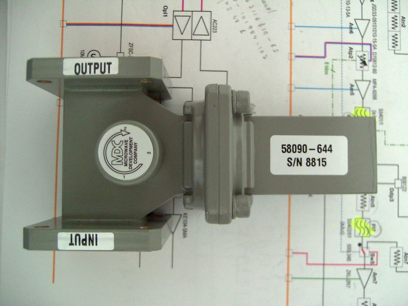
8.4 Waveguide Circulators
Waveguide RF circulators are often selected for higher power and lower loss requirements.
9. Advantages and Trade-Offs
9.1 Main Advantages
RF circulators improve directional signal flow, support transmitter and receiver isolation, help manage reflections, protect amplifier stages, and allow more efficient use of antennas and ports in RF systems.
9.2 Engineering Trade-Offs
Engineers must balance bandwidth, isolation, insertion loss, size, power handling, and cost. Small devices may be easier to integrate but harder to optimize for very high power.
10. FAQ
What is the main purpose of an RF circulator?
The main purpose of an RF circulator is to direct signal flow between ports in a fixed sequence, helping RF systems manage transmission, reception, and reflected power.
How is an RF circulator different from an isolator?
An RF circulator is usually a three-port non-reciprocal device, while an isolator is often formed by terminating one port of a circulator so that reverse energy is absorbed rather than returned.
Why are RF circulators used in radar systems?
They are used to separate transmit and receive paths while supporting shared-antenna operation and protecting sensitive receiver circuitry.
Can RF circulators protect power amplifiers?
Yes. RF circulators can redirect reflected power away from the amplifier output, helping improve stability and reliability.
What affects RF circulator performance the most?
Important factors include insertion loss, isolation, VSWR, bandwidth, power handling, structure type, and how well the device is matched within the full RF system.
References
- Microwaves101, “Circulators”
- TDK Product Overview, “Isolators/Circulators CU Series”
- COMSOL Blog, “Investigating a Three-Port Ferrite Circulator Design with RF Simulation”
- Wikimedia Commons, “Circulator-symbol-CW.svg”
- Wikimedia Commons, “Circulator-based_isolator.svg”
- Wikimedia Commons, “Coaxial_Circulators.jpg”
- Wikimedia Commons, “Phased array radar AN TPS-59.jpg”
- Wikimedia Commons, “AisladorG.JPG”
Recommended Products


.jpg)

Keith Wong
Marketing Director, Chengdu Hertz Electronic Technology Co., Ltd. (Hzbeat)
Keith has over 18 years in the RF components industry, focusing on the intersection of technology, healthcare applications, and global market trends.