Sub-1 GHz RF Circulators: Low-Frequency Design Challenges and Engineering Trade-Offs
A deep, focused engineering guide to Sub-1 GHz RF circulators. Learn why low-frequency RF circulator design is harder than expected: ferrite scaling, magnetic bias uniformity, bandwidth limits, insertion loss mechanisms, size trade-offs, power/thermal effects, and practical design strategies.
Designing a Sub-1 GHz RF circulator looks deceptively straightforward—until you try to achieve low insertion loss, high isolation, stable VSWR, and practical size at the same time. Below 1 GHz, the physics of wavelength, ferrite scaling, and magnetic biasing reshape the entire problem. This guide explains why RF circulator below 1 GHz engineering is harder than expected and how to think in trade-offs instead of wish lists.
1) What a Sub-1 GHz RF Circulator Must Do in Real Systems
A Sub-1 GHz RF circulator is a non-reciprocal three-port component that routes RF power from Port 1 → Port 2 → Port 3 → Port 1 (one rotation direction), enabling isolation between transmitter and receiver paths. In many VHF/UHF systems, a low-frequency RF circulator is used to:
- Protect power amplifiers: absorb or redirect reflected power caused by antenna mismatch.
- Improve system stability: reduce the effect of load variations and reflections on oscillation risk.
- Enable T/R sharing: help transmitter and sensitive receiver coexist on a single antenna path.
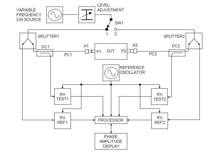
- Support measurement setups: isolate a device-under-test in a lab chain.
2) Why Low Frequency Changes the Rules
Below 1 GHz, the main “plot twist” is wavelength: λ = c / f. As frequency decreases, wavelength increases dramatically. That pushes you into larger resonant structures, larger ferrite volumes, and a larger magnetic circuit—exactly where uniformity and repeatability get harder.
Microwave mindset (often wrong below 1 GHz)
“Lower frequency means fewer parasitics, so it should be easier.”
Sub-1 GHz reality
Longer wavelength forces larger structures and makes magnetic biasing and bandwidth control more difficult.
In short: a low-frequency RF circulator is not a “scaled down” microwave circulator. It’s a multi-domain design—RF + magnetic + mechanical + thermal—where each domain can quietly ruin isolation or insertion loss.
3) Ferrite Scaling Laws Below 1 GHz
A ferrite circulator’s non-reciprocity comes from gyromagnetic behavior under a bias magnetic field. When you design a Sub-1 GHz RF circulator, you are essentially managing:
- Ferrite material parameters: saturation magnetization, linewidth (loss), temperature behavior.
- Geometry: ferrite disk size/thickness and junction structure.
- Bias condition: field strength and uniformity across the active ferrite region.
- Impedance environment: matching networks that keep VSWR and insertion loss acceptable over bandwidth.
At lower frequency, to keep the device operating in the desired non-reciprocal region, designers often need a larger ferrite junction and a more substantial magnetic assembly. That’s why “small” and “Sub-1 GHz RF circulator” frequently argue like roommates sharing one bathroom.
Scaling consequence: ferrite volume increases cost and sensitivity
Increasing ferrite volume can help achieve target isolation and bandwidth, but it also increases: magnetic loss contribution, mass, assembly complexity, and sensitivity to mechanical alignment. In a RF circulator below 1 GHz, “geometry” is not packaging—it’s performance.
4) Magnetic Bias Field Uniformity: The Hidden Boss Fight
Engineers talk about insertion loss and isolation because they are easy to measure. But the “root variable” behind many failures in a Sub-1 GHz RF circulator is bias field uniformity. When the ferrite region is larger, maintaining a consistent bias field across it becomes significantly harder.
Common low-frequency biasing pitfalls
- Edge field gradients: larger ferrite disks see stronger differences between center and edge bias.
- Air-gap sensitivity: small gap errors can noticeably shift the effective field strength and symmetry.
- Temperature drift: magnets and yokes change behavior with temperature, pushing the operating point.
- Mechanical stress: clamping pressure and assembly strain can subtly change the magnetic environment.
If your low-frequency RF circulator meets spec at room temperature but fails at hot/cold, suspect the bias circuit first, not the RF matching network. At Sub-1 GHz, the magnetic operating point is often the narrowest bottleneck.
5) Bandwidth Limits, Q, and the “Narrow Window” Problem
A repeating pattern in Sub-1 GHz RF circulator programs is “the bandwidth looked fine in early samples, then it collapsed when we tightened size.” That happens because bandwidth is constrained by:
- Ferrite linewidth and effective loss: higher loss broadens response but increases insertion loss.
- Operating point margin: a smaller bias margin leads to sharper, less forgiving behavior.
- Impedance matching limits: matching networks cannot create bandwidth that the core physics doesn’t allow.
In practical terms: many RF circulators below 1 GHz achieve only modest fractional bandwidth without becoming large. If you need wide bandwidth, you pay with size, magnet structure, or a more complex junction architecture.
| Goal | What you typically trade away | What often improves |
|---|---|---|
| Wider bandwidth | Size, cost, magnet complexity | Edge-of-band isolation stability |
| Smaller size | Bandwidth margin, isolation floor | Packaging convenience |
| Lower insertion loss | Bandwidth or power margin (depending on approach) | Efficiency and system noise |
| Higher power handling | Thermal drift risk, size, mechanical robustness demands | PA protection headroom |
6) Insertion Loss Mechanisms in Low-Frequency RF Circulators
It’s tempting to assume that a low-frequency RF circulator automatically has low insertion loss because conductor loss is “less severe.” But insertion loss is not only conductor loss. In a Sub-1 GHz RF circulator, the dominant contributors often include:
- Ferrite magnetic loss: depends on material linewidth and operating point.
- Mismatch loss: reflections from imperfect matching networks raise apparent insertion loss.
- Bias non-uniformity loss: non-ideal mode formation can increase dissipation.
- Connector and interface loss: especially at high power where contact quality matters.
How insertion loss, isolation, and VSWR entangle
In a perfect world, you’d independently tune insertion loss, isolation, and VSWR. In the real world, especially for a RF circulator below 1 GHz, these metrics are coupled: pushing for lower insertion loss by reducing ferrite loss may shrink bandwidth or destabilize isolation; pushing for “perfect” matching can introduce narrowband behavior that looks great at the center but collapses at edges.
7) Size vs. Performance Trade-Offs (and What “Miniaturization” Really Costs)
Everyone wants miniaturization. Below 1 GHz, miniaturization is possible—but it usually comes with a bill. For a Sub-1 GHz RF circulator, shrinking size tends to reduce your “operating margin”:
- Less tolerance to magnet drift and temperature shift
- More sensitivity to assembly variation
- Narrower bandwidth and sharper isolation features
- Harder-to-control impedance transitions and parasitics
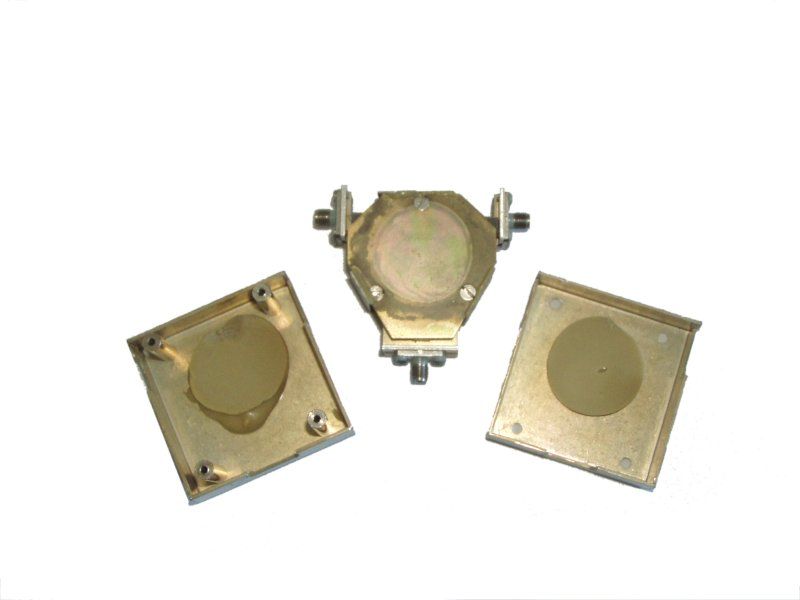
Common Sub-1 GHz implementations (and why coaxial often wins)
At VHF/UHF, coaxial architectures are common for a low-frequency RF circulator because they offer robust power handling and a more controllable current path. Microstrip-style structures often become physically large and may require careful EM containment to prevent unwanted radiation or coupling.
8) Power, Thermal Drift, and Long-Duty Operation
Many RF circulators below 1 GHz live in transmitter chains with long duty cycles or high peak power. Thermal behavior matters because ferrite parameters and magnet properties shift with temperature. Typical field failures that look like “mystery drift” can be explained by:
- Magnet temperature coefficient: bias field changes as the magnet heats.
- Ferrite temperature dependence: effective permeability and loss can change, shifting the sweet spot.
- Mechanical expansion: air gaps and alignment can move by small amounts with big RF consequences.
For a Sub-1 GHz RF circulator used in a PA protection role, it’s not enough to pass a short bench test. You want temperature soak testing, power cycling, and repeat measurements to confirm that insertion loss and isolation are stable over time.
9) Manufacturing Tolerances and Repeatability
Sub-1 GHz devices are often “mechanically bigger,” but that does not mean they are mechanically forgiving. In fact, a low-frequency RF circulator can be extremely sensitive to tolerances because the magnetic circuit and geometry dominate performance. Key tolerance drivers include:
- Air gap control: tiny gap changes can noticeably shift bias strength and uniformity.
- Ferrite thickness flatness: affects field distribution and effective junction behavior.
- Port alignment and connector torque: impacts repeatability, especially in production and field service.
- Clamping force consistency: mechanical stress can modulate magnetic behavior.
10) Practical Design Strategies and Test Checklist
If you’re building or sourcing a Sub-1 GHz RF circulator, use a strategy that respects the physics: start with operating margin, then optimize size and bandwidth, not the other way around.
Design strategy (what experienced teams do)
- Start with magnetic design: ensure bias uniformity and stable operating point before aggressive RF matching.
- Pick ferrite for the mission: linewidth, temperature range, and repeatability matter as much as “headline” loss.
- Design for manufacturability: define assembly torque, gap targets, and alignment fixtures early.
- Use matching networks for shaping—not miracles: matching can smooth response, but it can’t defeat limited physical bandwidth.
- Validate with stress: temperature + power + time. A low-frequency RF circulator that survives these will survive your customers.
Test checklist for Sub-1 GHz RF circulator validation
- S-parameter sweep: verify insertion loss (S21), return loss/VSWR (S11), and isolation (e.g., S31 or reverse paths) across the full band.
- Thermal sweep: repeat measurements at cold/room/hot to observe isolation dips and loss drift.
- Power handling: validate at realistic CW and peak power; monitor temperature rise and performance shift.
- Repeatability: measure multiple units and re-mate connectors to quantify production and field variability.
11) Conclusion
A Sub-1 GHz RF circulator is difficult not because the concept is complicated, but because the design space is unforgiving. Below 1 GHz, longer wavelength pushes you toward larger ferrite structures and larger magnetic circuits, where bias uniformity, bandwidth margin, insertion loss control, and manufacturability become tightly coupled.
The winning approach is to design (or select) a low-frequency RF circulator by prioritizing operating margin: stable biasing, repeatable assembly, and realistic bandwidth goals—then optimize size and cost without crossing the line where small variations produce big failures.
12) FAQ
Q1: Why is a Sub-1 GHz RF circulator often larger than a microwave circulator?
Lower frequency means longer wavelength, which pushes ferrite junctions and magnetic structures to larger physical dimensions. That larger geometry also makes bias field uniformity harder, so designers often use more substantial magnetic circuits.
Q2: Does an RF circulator below 1 GHz always have lower insertion loss?
Not always. Insertion loss in a low-frequency RF circulator includes ferrite magnetic loss, mismatch loss, and bias non-uniformity effects. Larger ferrite volume can increase the total magnetic loss contribution even if conductor loss is modest.
Q3: Why is bandwidth limited in many low-frequency RF circulators?
Bandwidth is constrained by ferrite material behavior and the stability of the operating point under bias. Matching networks can help shape response, but they cannot create wide fractional bandwidth if the core physics is narrow.
Q4: What is the most common reason a Sub-1 GHz RF circulator passes at room temperature but fails in the field?
Bias and thermal drift are frequent culprits. Changes in magnet field strength with temperature, ferrite parameter drift, and mechanical expansion can shift the operating point, causing isolation dips or increased insertion loss.
Q5: How do I choose between size and performance in a Sub-1 GHz RF circulator?
Decide which metric is non-negotiable: bandwidth, isolation floor, insertion loss, or power handling. In low-frequency RF circulator design, optimizing one often taxes another. A realistic spec with margin beats a heroic spec that collapses in production.
13) References
- Pozar, D. M., Microwave Engineering, Wiley.
- Helszajn, J., Nonreciprocal Microwave Junctions and Circulators.
- IEEE Transactions on Microwave Theory and Techniques (papers on ferrite devices, non-reciprocal components, and biasing effects).
- Wikimedia Commons images used in this article (see each file page for license and attribution details).
Recommended Products

.jpg)


Keith Wong
Marketing Director, Chengdu Hertz Electronic Technology Co., Ltd. (Hzbeat)
Keith has over 18 years in the RF components industry, focusing on the intersection of technology, healthcare applications, and global market trends.