RF Circulator Technology Advances for 5G, Radar and Quantum Systems in 2026
In 2026, RF circulator development is being shaped by wideband 5G front ends, high-duty radar transmit chains, and low-noise quantum microwave systems. This engineering report reviews ferrite physics under magnetic bias, key trade-offs, integration formats, reliability drivers, and validation practices with verifiable references.
Introduction
A three-port RF circulator routes power directionally (commonly 1→2, 2→3, 3→1). In practical transmit chains, the third port is often terminated with a matched load so that reflected power from a mismatched antenna is diverted away from a power amplifier. This architecture improves stability and reduces the risk of damaging voltage/current conditions during high VSWR events. These functions are widely documented. What has changed is the operating environment: higher bandwidth utilization, higher average power density, tighter packaging, and stricter noise or stability budgets.
Because a ferrite-based RF circulator depends on a magnetic operating point, performance is not only a function of frequency—it is also a function of temperature, mechanical tolerance, and self-heating under power. As systems become more broadband and more compact, these second-order factors become first-order in practice. For that reason, “technology advances” in RF circulators should be understood as advances in how designers control drift, ensure flatness across band edges, manage thermal gradients, and validate stability under real stress conditions.
1) Why 5G, radar, and quantum systems stress RF circulators differently
Although the RF circulator is often described with a single set of specifications, its dominant stress factors vary by application. Understanding those differences is the first step toward a rigorous selection.
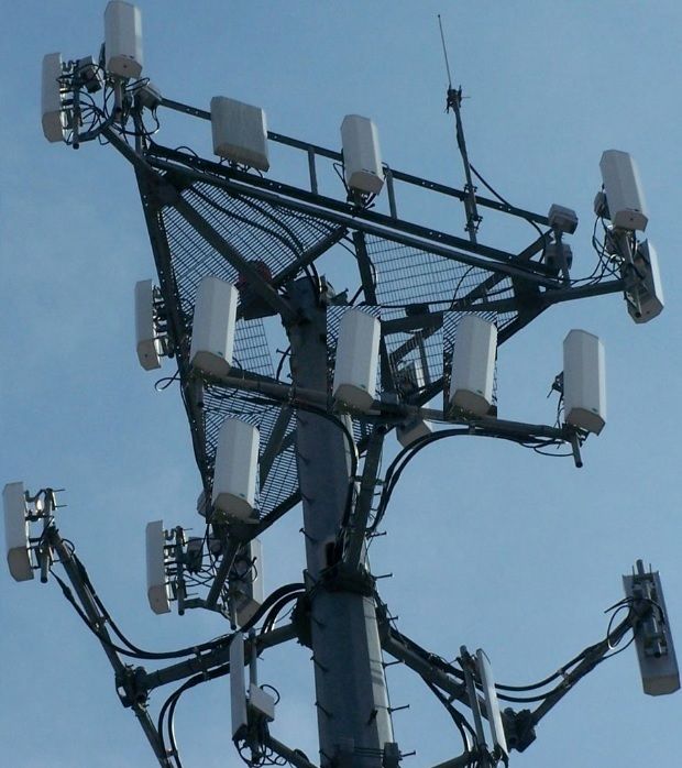
5G radio units
Wide bandwidth utilization, multi-carrier operation, and strict linearity requirements make flatness important. A circulator that meets isolation at center frequency but degrades at band edges can increase reverse leakage and reduce stability margin across channels.
Radar transmit chains
High average power, high duty cycle, and harsh environments make thermal stability and mismatch survivability critical. Self-heating can shift the magnetic operating point and degrade isolation or increase insertion loss if thermal boundaries and derating are not engineered.
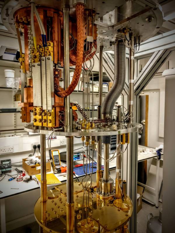
Quantum microwave systems
Low-noise chains use non-reciprocal routing to protect sensitive devices from reflections and amplifier backaction noise. Here, isolation behavior and repeatability within the chain architecture are emphasized.
Test & measurement
Repeatability dominates. Connector torque, fixture repeatability, and post-stress drift can matter as much as nominal insertion loss.
Across these domains, the most credible advances are those that reduce sensitivity to operating conditions: improved bias stability, better thermal design, and integration approaches that preserve performance when the component becomes part of a real assembly, not an ideal bench setup.
2) Operating principle: ferrite non-reciprocity and magnetic bias
A ferrite-based RF circulator relies on gyromagnetic behavior under a static magnetic bias. Under bias, ferrite exhibits tensor permeability, enabling direction-dependent phase behavior. In a symmetric junction (often modeled as a Y-junction), the device can be biased such that signals combine constructively at the intended output port and cancel at the isolated port. This operating principle is discussed in multiple technical notes and application references on ferrite devices.
In practice, the circulator’s operating point is determined by the coupling of:
- Ferrite material properties: saturation magnetization, linewidth (loss-related), dielectric constant, and temperature dependence.
- Magnetic circuit: magnet type, field strength, alignment, and uniformity at the ferrite region.
- Microwave structure: junction geometry and matching networks that shape bandwidth, ripple, and port match.
The key engineering implication is that non-reciprocity must be tuned and held stable. If magnetic bias changes with temperature, if the ferrite region sees a thermal gradient, or if mechanical tolerances shift field distribution, insertion loss and isolation can drift. For wideband systems, modest drift can turn a pass at room temperature into a borderline result at band edges. For high-power systems, drift may appear only after the device warms under duty cycle.
3) Key parameters and what they mean in real hardware
The basic parameter set—Insertion Loss (IL), Isolation (ISO), VSWR/Return Loss, Bandwidth, and Power Handling—is universal. The 2026 shift is that engineers increasingly treat these as envelopes, not single numbers. Below is a practical interpretation that supports rigorous acceptance criteria.
| Parameter | What it physically represents | Why it matters | What to verify to avoid false confidence |
|---|---|---|---|
| Insertion Loss | Dissipative + mismatch loss on the forward path (e.g., 1→2) | Efficiency, thermal load, noise budget in cascaded chains | Measure across band edges and after warm-up / power exposure |
| Isolation | Suppression on the reverse-coupled path (e.g., 1→3) | Receiver protection, stability margin, reduced leakage | Check minimum isolation across full band and temperature range |
| VSWR | Port match quality | Reflection control, ripple, repeatability with transitions | Verify after installation torque/mounting, not only as a loose component |
| Bandwidth | Range over which IL/ISO/VSWR meet limits | Multi-band use, wide instantaneous bandwidth waveforms | Validate band edges; quantify ripple and drift with temperature |
| Power Handling | Thermal + field stress limits under defined boundaries | Survivability and stability under duty cycle and mismatch events | Define thermal boundary conditions; check post-stress drift |
A rigorous specification uses statements such as “IL shall not exceed X dB across the operating band at specified temperatures,” and “ISO shall remain above Y dB at all frequencies in-band.” This avoids reliance on best-case peaks and focuses on minimum guarantees.
4) Wideband behavior: flatness, ripple, and band-edge stability
When an RF circulator is used in wideband systems, the question is not only whether it works at the center frequency. The question is whether it remains predictable at band edges, where matching is often weaker and parasitics become more visible. Wideband behavior is shaped by junction geometry, matching strategy, and packaging parasitics.
Engineers commonly encounter two wideband pitfalls:
- Edge isolation drop: isolation may be excellent near the tuned region but fall below minimum at the low/high edge. In multi-carrier systems, edge performance is not optional.
- Ripple and calibration sensitivity: ripple in insertion loss/return loss can translate into gain variation across the signal band, complicating calibration and potentially increasing chain sensitivity to mismatch.
A credible advance here is not a headline claim of 鈥渦ltra wideband鈥?but a demonstrable flattening strategy: improved matching topologies, better control of transitions, and tighter tolerance control in assembly that reduces unit-to-unit variability. These improvements show up in measured envelopes, not in slogans.
5) High-power radar chains: thermal design, derating, and mismatch survivability
For radar transmit chains, an RF circulator often sits in the highest-stress region: high average power, high duty cycle, and exposure to mismatch conditions created by antenna dynamics or array coupling. Under these conditions, the dominant risk is not a small-signal mismatch; it is self-heating and thermal gradients that shift the magnetic operating point and degrade isolation or increase insertion loss.
Example (HzBeat): An X-Band WR-90 Waveguide RF Circulator for Radar Transmit Chains
To anchor the radar discussion in a verifiable specification, the following example is a published waveguide RF circulator entry in X-band. In radar transmit chains, the engineering emphasis is typically on predictable behavior under duty cycle and mismatch events, which makes thermal boundary conditions and post-stress drift checks as important as nominal small-signal S-parameters.
This example should be treated as a datasheet-style reference rather than a guarantee of in-system performance. For radar qualification, map the published limits to explicit checks: (1) verify insertion loss and isolation after thermal equilibrium at representative duty cycle, (2) define mismatch event conditions (VSWR level and duration) and re-measure after the event to quantify drift, and (3) control mechanical interfaces (flange alignment and torque procedure), since waveguide joints can directly affect return loss and ripple.
Thermal engineering is therefore part of RF circulator engineering. Power rating must be interpreted under defined boundary conditions: baseplate temperature, mounting flatness, interface materials, airflow, and the expected mismatch profile (VSWR magnitude and duration). The same device can behave differently when installed on a high-conductivity heat-spreading chassis versus a poorly coupled mounting surface.
A robust qualification process for high-power use typically includes:
- Warm-up characterization: measure performance after thermal equilibrium under representative duty cycle.
- Mismatch event testing: characterize survivability at defined VSWR levels and event durations.
- Post-stress re-measurement: quantify drift in insertion loss and isolation after power exposure.
This avoids a common trap: a device that survives a power event but drifts enough to reduce protection margin can still be a system risk.
6) Integration formats: coaxial vs microstrip vs drop-in vs waveguide
Different physical formats correspond to different integration realities. The correct choice depends on frequency band, power level, packaging constraints, and system stability requirements.
| Format | Typical strengths | Typical integration risks | Where it fits well |
|---|---|---|---|
| Coaxial RF circulator | Convenient interconnect, broad usage in RF labs and many systems | Connector torque repeatability, cable strain, fixture sensitivity | General RF chains, test setups, many sub-6 GHz deployments |
| Microstrip circulator | Compact integration, PCB-level routing compatibility | Stack-up tolerance, launch transitions, parasitic coupling, nearby metal affecting bias | Compact RF modules where PCB control is strong |
| Drop-in circulator | Module-friendly, controlled mechanical interfaces | Solder/attach quality, rework cycles, pressure and flatness dependencies | Production modules requiring repeatable mechanical assembly |
| Waveguide circulator | High-frequency suitability, robust power handling in many use cases | Flange alignment, surface finish, torque procedures, gasket effects | Radar and SATCOM waveguide chains |
PCB-integrated formats deserve special care. A microstrip RF circulator becomes part of a transmission-line environment: substrate thickness and dielectric tolerance affect impedance; launch transitions and via fences affect return paths and ripple; nearby ferromagnetic fasteners or steel covers can perturb magnetic bias distribution. These are common sources of unit-to-unit variation and band-edge degradation.
Example (HzBeat): A Sub-6 GHz Drop-in RF Circulator for 5G Front-End Protection
To anchor the radar discussion in a verifiable specification, the following example is a published waveguide RF circulator entry in X-band. In radar transmit chains, the engineering emphasis is typically on predictable behavior under duty cycle and mismatch events, which makes thermal boundary conditions and post-stress drift checks as important as nominal small-signal S-parameters.
To avoid overstating what any single table entry can guarantee, the example should be treated as a published specification reference: final performance in an assembly depends on transitions, mounting flatness, and thermal boundary conditions. In qualification, map the example specification to acceptance checks: (1) verify worst-case isolation at band edges to control reverse leakage and stability margin, (2) verify insertion loss after warm-up at representative duty cycle to detect thermal drift, and (3) verify port match after installation/mounting procedure to avoid assembly-induced mismatch.
When a waveguide RF circulator is used, mechanical interfaces become RF interfaces. Poor flange alignment or inconsistent torque can introduce reflections and ripple that appear as degraded VSWR. Therefore, a rigorous installation procedure is often part of the qualification plan.
Internal navigation by format (optional for your site structure) can be placed naturally where the reader is comparing options: RF circulator, microstrip circulator, drop-in circulator, waveguide circulator.
7) Quantum microwave systems: isolation against backaction noise
In quantum microwave systems, circulators and isolators are used to route signals directionally and to reduce the propagation of unwanted noise back toward sensitive quantum devices. A commonly cited motivation is to limit amplifier backaction and reflections that would otherwise couple noise into the quantum circuit. This role is described in peer-reviewed discussions of non-reciprocal microwave devices for quantum technologies.
Even when the circulator itself operates at room temperature in some setups, the overall chain emphasizes stability and repeatability. Small changes in insertion loss can influence attenuation budgets, and changes in isolation can influence how effectively noise is prevented from returning upstream. For this reason, qualification often focuses on drift, repeatability, and well-defined measurement conditions.
8) Reliability: common drift and failure mechanisms
RF circulators often sit near antenna interfaces and high-power stages, so they see real-world stresses: thermal cycling, vibration, shock, and mismatch events. Many issues are not sudden failures but gradual shifts that reduce protection margin or degrade flatness until the system becomes unstable under certain conditions.
Common drift and failure contributors include:
- Thermal cycling fatigue: repeated temperature swings can degrade joints and interfaces, producing gradual S-parameter drift.
- Mechanical shock/vibration: cracking or shifting of ferrite/magnet assemblies can alter magnetic field distribution.
- Mismatch heating: high VSWR events can increase dissipation in termination paths, raising local temperatures and accelerating drift.
- Assembly variability: connector torque, flange alignment, and mounting flatness affect repeatability and can masquerade as device variation.
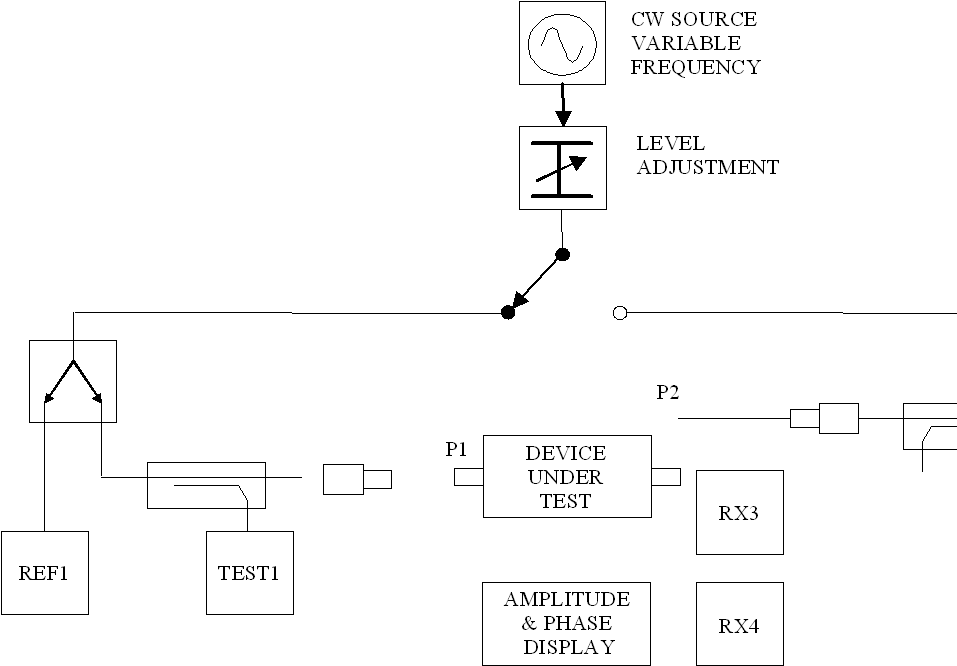
9) Validation methods: beyond a single room-temperature S-parameter sweep
A single room-temperature, low-power VNA sweep is necessary but not sufficient. A rigorous validation plan aligns measurement conditions with the intended application. This does not require exotic equipment; it requires discipline in defining boundaries and repeating measurements after stress.
A practical validation plan usually includes:
- Band-edge verification: check IL/ISO/VSWR across the full band, with attention to minimum isolation and maximum insertion loss.
- Temperature characterization: measure across the intended temperature range and quantify drift of key metrics.
- Power warm-up checks: for high-power chains, measure after thermal equilibrium under representative duty cycle.
- Mismatch survivability: evaluate defined VSWR conditions and durations; re-measure after stress to quantify drift.
- Repeatability sampling: measure multiple units and report distribution (min/max/typical) to avoid relying on a single “golden” unit.
This approach avoids overconfidence from idealized measurements and supports defensible acceptance criteria.
10) Practical selection and qualification checklist
The checklist below is designed to be unambiguous and measurable. It avoids assumptions and helps engineers translate system needs into qualification steps.
10.1 Define the operating envelope
- Frequency band and required in-band limits for insertion loss, isolation, and VSWR.
- Instantaneous bandwidth and waveform characteristics (duty cycle, crest factor where relevant).
- Environment: temperature range, vibration/shock requirements, humidity exposure if applicable.
- Mismatch expectations: likely VSWR levels during antenna detuning or fault conditions.
10.2 Define acceptance as envelopes, not single points
- Maximum insertion loss across the full band and over temperature.
- Minimum isolation across the full band and over temperature.
- Maximum VSWR at all ports after installation/mounting procedures.
- Maximum drift allowed after stress (thermal cycling, power burn-in, mismatch events).
10.3 Define test boundaries and documentation
- VNA calibration method and fixture description.
- Mechanical procedures: connector torque or flange torque specification and repeatability rules.
- Power test boundaries: baseplate temperature measurement, mounting interface definition, airflow conditions.
- Sampling plan: number of units, pass/fail definition, and re-test policies.
Product list: microstrip circulator, drop-in circulator, waveguide circulator.
Conclusion
The most defensible interpretation of “RF circulator technology advances” in 2026 is not a single sensational metric, but improved control of real-world variability: stability across band edges, reduced sensitivity to temperature and self-heating, integration methods that preserve performance in compact assemblies, and qualification practices that measure drift after stress. These advances align directly with the needs of 5G infrastructure, high-duty radar chains, and quantum microwave systems.
A rigorous RF circulator selection process defines performance as envelopes across operating conditions and validates beyond a single room-temperature sweep. When this discipline is applied, RF circulators deliver their core value: directional routing that protects active devices, improves stability, and maintains predictable behavior in real deployments.
FAQ
Is an RF circulator the same as an RF isolator?
A circulator is typically a three-port non-reciprocal device. When one port is terminated with a matched load, the remaining two ports behave like an isolator in many applications.
Why can an RF circulator pass lab S-parameter tests but show issues in the field?
Because field conditions introduce stressors that quick bench tests often omit: thermal gradients under duty cycle, mismatch events, vibration/shock, and installation variability. These can shift the magnetic operating point or introduce drift in insertion loss and isolation.
What should be prioritized for wideband 5G front ends?
Prioritize minimum isolation and maximum insertion loss across the full band (including edges) and quantify ripple. Flatness and stability across operating conditions are often more predictive than best-case peaks at center frequency.
What should be prioritized for high-power radar chains?
Prioritize thermal boundary definition, derating discipline, mismatch survivability characterization, and post-stress drift limits. A device that survives but drifts can still reduce protection margin over time.
Why are circulators and isolators used in quantum microwave systems?
They are used to route signals directionally and to reduce unwanted noise or backaction from propagating back toward sensitive quantum circuits.
References
- RF Circulators operating principle (PDF): https://www.rf-ci.com/wp-content/uploads/2015/09/KB-001_Operating-Principle.pdf
- Basic facts about circulators & isolators (PDF): https://escies.org/download/webDocumentFile?id=63324
- Application note defining a circulator (PDF): https://valvo.com/wp-content/uploads/2017/12/CIRCULATOR.pdf
- Peer-reviewed quantum context (PMC article): https://pmc.ncbi.nlm.nih.gov/articles/PMC10799849/
- General educational reference (Radar tutorial): https://www.radartutorial.eu/17.bauteile/bt33.en.html
- HzBeat example (drop-in circulator page): https://www.hzbeat.com/drop-in-circulator/typical-drop-in-circulator.html
- HzBeat radar example (waveguide circulator PDF): https://www.hzbeat.com/specification/waveguide-circulator/junction-waveguide-circulator/HWCT82T125G.pdf
- Wikimedia Commons images used in this article (accessed via Special:FilePath):
- 5G antenna photo: https://commons.wikimedia.org/wiki/File:Celluar_Antenna_with_tower_for_5G.jpg
- Phased array radar photo: https://commons.wikimedia.org/wiki/File:Phased_array_radar.jpg
- PCB photo: https://commons.wikimedia.org/wiki/File:Printed_circuit_board_2008.jpg
- Dilution refrigerator photo: https://commons.wikimedia.org/wiki/File:Dilution_Refrigerator_(39016294284).jpg
- VNA image: https://commons.wikimedia.org/wiki/File:Vector_network_analyzer.PNG
Internal navigation: microstrip circulator · drop-in circulator · waveguide circulator
Recommended Products


Sara
Sara is a Brand Specialist at Hzbeat, focusing on RF & microwave industry communications. She transforms complex technologies into accessible insights, helping global readers understand the value of circulators, isolators, and other key components.