What Are the Advantages of Coaxial RF Circulators?
A deep SEO article on the advantages of coaxial RF circulators, including mismatch protection, power handling, connectorized integration, mechanical reliability, qualification strategy, and selection guidance for real RF and microwave systems.
Introduction
Every experienced RF engineer eventually learns the same lesson: elegant schematics are easy, but real hardware lives in a world of reflected power, drifting loads, connector wear, thermal rise, and field servicing. The coaxial RF circulator matters because it is one of the few passive components that directly addresses those realities. It does not merely route energy from one port to the next. It buys margin. It reduces risk. It protects expensive active stages from ugly mismatch behavior. And perhaps most importantly, it does all of this in a format that integrates naturally with connectorized RF assemblies.
That practical advantage is why the RF circulator in coaxial form is still widely used even in an era dominated by high-density modules and aggressive miniaturization. Microstrip and drop-in parts can be excellent for embedded architectures. Waveguide solutions dominate where power and frequency push into harsher territory. But the coaxial RF circulator occupies a powerful middle ground: it provides the non-reciprocal behavior of a ferrite circulator while preserving the mechanical familiarity, modularity, and field-replaceability of coaxial interconnects.
This article takes a deeper path than a standard product overview. Instead of repeating the usual phrases about “low insertion loss” and “high isolation” in circles until everyone falls asleep, we will focus on why these advantages matter at the system level, what coaxial packaging specifically adds beyond the basic circulator function, where coaxial devices outperform other package types, and how to choose one without being fooled by a nice-looking data sheet.
What Is a Coaxial RF Circulator?
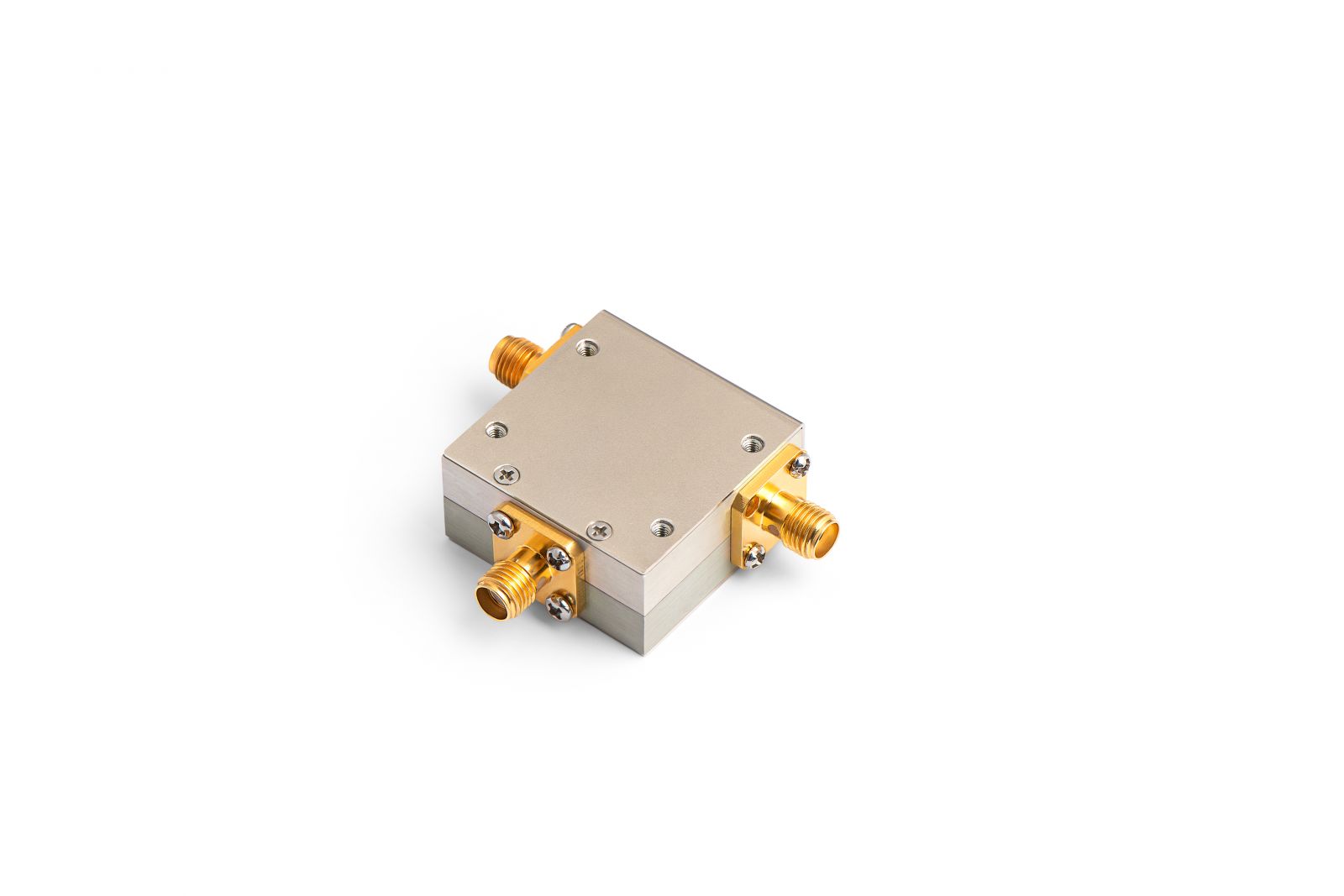
A coaxial RF circulator is a three-port passive, non-reciprocal device that routes energy sequentially from one port to the next. In a clockwise device, power entering port 1 exits port 2; power entering port 2 exits port 3; power entering port 3 exits port 1. That directional behavior comes from ferrite materials under magnetic bias, which is why circulators and isolators are part of the broader ferrite circulator family.
The definition is simple. The consequences are not. In a transmit path, the circulator can steer reverse power away from a power amplifier and toward a load. In a shared-antenna path, it can separate transmit and receive functions. In a laboratory chain, it can keep reflections from contaminating measurements or damaging expensive sources. A circulator is passive, but it acts like a traffic officer with no patience for wrong-way drivers.
The word “coaxial” describes the interface and packaging. Instead of planar pads or waveguide flanges, the component uses coaxial connectors such as SMA, N, TNC, or 2.92 mm. That changes far more than mechanical convenience. It changes integration strategy, qualification workflow, maintenance burden, and field serviceability. Those are not side notes. They are often the real reasons a coaxial device is chosen.
The Core Advantages of Coaxial RF Circulators
1. They protect expensive active hardware from reflected-power abuse
This is the advantage everyone mentions, but not everyone fully appreciates. A good coaxial RF circulator protects amplifiers, drivers, low-noise front ends, and test equipment from reverse energy created by load mismatch. Antennas do not stay perfectly matched in the real world. Ice forms. radomes age. connectors loosen. cables flex. test fixtures lie. When the load moves away from 50 ohms, reflected power heads back upstream looking for trouble.
Without a circulator, that trouble lands directly on the active device. Gain may compress, efficiency may drop, thermal stress rises, and long-term reliability gets worse. In severe cases, oscillation, load pull, or outright damage can occur. With a coaxial RF circulator, the reverse energy is diverted to port 3, where it can be absorbed by a matched termination or managed by the system architecture. The result is not just “protection” in an abstract sense. It is better uptime, better amplifier behavior under mismatch, and lower lifecycle risk.
2. They create a cleaner boundary between subsystems
One subtle but important benefit of the RF circulator is that it acts as a directional buffer between hardware blocks that were not designed together perfectly. This matters in the messy middle of real product development. A PA vendor may optimize for output power. An antenna vendor may optimize for bandwidth or form factor. A cable harness may introduce repeatability errors. A filter block may shift its impedance over temperature. The circulator reduces how aggressively those imperfections couple backward into the source.
That subsystem decoupling is a hidden advantage. It can simplify integration, reduce the sensitivity of the chain to load variation, and make the overall design more tolerant of component spread. In other words, the circulator often buys engineering forgiveness. In RF, forgiveness is expensive. A microwave circulator that provides it is doing real work.
3. Coaxial packaging lowers integration friction
This is where coaxial designs start to separate themselves from many embedded options. A connectorized device can be installed directly between existing cables, modules, or instruments. That means fewer PCB redesigns, fewer custom cavities, fewer packaging surprises, and faster A/B validation during development.
For bench work, this is a gift. Engineers can insert the part, measure it, replace it, compare variants, and qualify alternate suppliers without cutting metal or respinning a board. For production hardware, connectorized integration can also simplify maintenance and modular replacement. A coaxial RF circulator is therefore not only an RF component; it is also a workflow component. It makes development and service less painful, which is not a glamorous sentence but is often the truest one.
4. They are mechanically rugged and easier to support in the field
Many coaxial circulators are built inside robust metal housings with threaded or flange-mounted connector interfaces. That architecture naturally supports stronger mechanical retention, better shock and vibration resistance, and easier replacement than many embedded planar solutions. In communication infrastructure, defense electronics, industrial systems, and outdoor deployments, this matters a great deal.
Mechanical ruggedness is not just about surviving a drop test. It affects connector repeatability, grounding integrity, thermal contact, and long-term stability after repeated installation cycles. A rugged coaxial RF circulator is often chosen because it can take mechanical life seriously rather than treating it as a footnote beneath S-parameter plots.
.png)
5. They support meaningful power handling without the fragility of very dense integration
Power handling is always a system story, not a marketing badge. A circulator that looks excellent at nominal conditions may behave differently when average power, peak power, reflected power, and case temperature all rise together. Coaxial packaging often helps here because it can provide more physical volume for conductors, ferrite structures, magnetic bias elements, and heat flow than highly compact PCB-centric formats.
That does not mean every coaxial unit is automatically a monster power device. It means the package class is well suited to robust power-handling design. This is why coaxial circulators are common in amplifier protection chains, high-power communication links, radar subsystems, and industrial RF equipment where reverse power cannot simply be wished away.
6. They are often the most service-friendly way to deploy ferrite non-reciprocity
A ferrite circulator is only useful if the system can keep using it over time. Field replacement is much simpler when the part lives between connectors rather than deep inside a board stack or sealed cavity. If a site technician can isolate a failed or suspect component and replace it without disassembling the entire radio or test rack, the architecture is already winning.
Serviceability is rarely celebrated in marketing copy because it is less shiny than bandwidth. But for long-life programs, it directly affects operational cost and downtime. That makes service-friendly packaging one of the most practical advantages of the coaxial RF circulator.
7. They fit naturally into modular qualification and supplier strategy
Connectorized components are easier to qualify as discrete modules. That has purchasing and program-management benefits as well as RF benefits. It is simpler to run incoming inspection, maintain spare inventory, validate alternates, and document replacement procedures when the non-reciprocal device is a modular coaxial block rather than a custom embedded feature.
This matters especially when organizations want dual-source strategies or when they need to qualify multiple bands with a consistent integration method. A coaxial RF circulator supports that modularity better than many more integrated alternatives.
8. They can reduce debug time in the lab
Here is a painfully real advantage: when something is wrong, connectorized parts are easier to isolate. RF debugging is already a haunted forest. Do not add hidden passive components buried in a board cavity unless you must. A coaxial device lets engineers move, swap, or bypass the part quickly during troubleshooting. That faster fault isolation can save days or weeks in a complex program.
Electrical Advantages That Matter Beyond the Brochure
Low insertion loss is not just about efficiency
Yes, lower insertion loss means more power reaches the load and less heat is generated in the component. But in a practical system, low loss also protects link budget, preserves receiver sensitivity, and reduces how much performance you must “buy back” elsewhere. If the circulator sits between a PA and antenna, extra loss increases thermal burden and reduces effective radiated power. If it sits in a sensitive signal path, it can degrade noise performance or margin.
Isolation is not just a nice number, it is a stability tool
Isolation controls how much reverse energy leaks where it should not. In many systems, stronger isolation helps reduce self-interference, suppresses the impact of mismatch on upstream stages, and improves the predictability of behavior as operating conditions change. Engineers sometimes treat isolation as a catalog comparison field. In reality, it is one of the reasons the entire chain remains calm instead of turning dramatic.
Good VSWR improves tolerance to imperfect ecosystems
A circulator is not used in isolation; it lives among connectors, cables, filters, antennas, and amplifiers. Good matching lowers the reflection created by the circulator itself and reduces how badly the whole chain compounds mismatch effects. A mature microwave circulator design therefore contributes to smoother system behavior even before reverse power events occur.
Why Coaxial Circulators Often Beat Other Package Types in Practical Deployments
| Package Type | What It Does Best | Where Coaxial Still Wins | Main Trade-Off |
|---|---|---|---|
| Coaxial RF Circulator | Balanced mix of power handling, modularity, ruggedness, and easy cable-based integration | Field replacement, lab debugging, subsystem qualification, connectorized installations | Larger than highly integrated planar devices |
| Microstrip Circulator | Compact integration into planar or module-level layouts | Coaxial is easier to replace, qualify, and support mechanically | Microstrip solutions can be more layout-sensitive and less service-friendly |
| Drop-in Circulator | Good compromise for embedded microwave modules | Coaxial reduces packaging friction when the chain is already connectorized | Requires tighter mechanical integration than connectorized parts |
| Waveguide Circulator | Exceptional performance at very high power or higher microwave / mmWave bands | Coaxial is often easier and cheaper for mainstream connectorized systems | Waveguide can be bulky, band-specific, and mechanically more demanding |
The comparison above explains why the coaxial RF circulator is often the sensible choice rather than the extreme one. It may not be the smallest package and it may not always be the highest-power solution. But when the system is connectorized, serviceable, qualification-heavy, or exposed to real-world mismatch events, coaxial packaging often delivers the best overall value.
Application Scenarios Where the Advantages Become Decisive
Shared-antenna transmit/receive paths
In T/R architectures, ferrite circulators are used to steer transmit energy toward the antenna while helping isolate the receive path. Microwaves101 notes that circulators are commonly used in duplexing and T/R modules, including cases where the circulator may sit outside the main module housing. That fits well with coaxial packaging because the component can remain external, accessible, and easy to replace when connectorized architecture is already present.
Amplifier protection chains
This is perhaps the most straightforward use case. If the power amplifier faces variable mismatch, a coaxial RF circulator plus termination gives the designer a practical way to redirect reverse power. That can reduce load-pull stress, improve long-term reliability, and help the amplifier behave more predictably under non-ideal conditions.
Base-station, repeater, and communication infrastructure hardware
Communication hardware values stability, maintainability, and predictable field service. These systems may live outdoors, face antenna variation, or require fast replacement procedures. Connectorized non-reciprocal hardware is therefore attractive because it aligns with the overall operational model.
Radar and pulsed systems
Radar hardware cares deeply about protecting sensitive front ends from the transmitter side of the chain. In these environments, isolation and power handling are not decorative specifications. They are survival tools. Depending on power and frequency, coaxial circulators may be used where connectorized mechanical robustness and modular replacement are favored.
Test and measurement benches
Bench systems are practically a love letter to coax connectors. Sources, analyzers, DUT fixtures, and protection accessories are already arranged in a cable-based ecosystem. A coaxial RF circulator fits into that world with minimal ceremony and makes experimental setups easier to modify and protect.

Design Details Behind the Advantages
Ferrite material quality
The performance of a ferrite circulator depends strongly on ferrite loss characteristics, bias response, uniformity, and temperature behavior. Better materials help the designer achieve lower insertion loss, more stable isolation, and better repeatability across production lots.
Magnetic bias control
Circulation only works correctly when the magnetic bias is well designed. Poor biasing hurts isolation and makes performance drift harder to control. Good bias design improves directional behavior over the intended operating band and environmental range.
Internal transmission-line geometry
Coaxial package geometry influences characteristic impedance, field uniformity, tuning behavior, and connector transition quality. The mechanical discipline of coaxial design can therefore support repeatable integration and good RF matching when executed properly.
Thermal path and enclosure design
Power handling is ultimately limited by temperature rise and by how well the structure tolerates reflected and transmitted energy over time. Coaxial housings often provide useful thermal mass and better opportunities for mechanical heat sinking than very compact planar solutions.
How to Evaluate a Coaxial RF Circulator More Seriously
Too many buyers compare circulators like they are shopping for coffee mugs: frequency, power, connector, done. That is how expensive problems sneak in later. A better evaluation includes the following questions:
- What is the specified insertion loss across the full operating band, not only at center frequency?
- How does isolation behave at band edges and across temperature?
- Is the quoted power rating average, peak, reflected, or some carefully massaged combination?
- What connector family is used, and does it truly match the system’s frequency and mechanical requirements?
- What happens under load mismatch? This is the question that separates comfortable brochure reading from actual engineering.
- Does the package support your mounting, grounding, and thermal strategy?
- Can the supplier provide test data, qualification evidence, and repeatable production control?
It is also wise to ask whether you need a typical narrowband unit, a broadband coaxial unit, or a truly high-power design. These are not interchangeable categories. Broadband parts may trade some performance for wider coverage, while high-power parts often reflect very different thermal and mechanical priorities.
When a Coaxial RF Circulator Is Not the Best Answer
Let us not turn admiration into superstition. A coaxial RF circulator is not always optimal. If your top priority is embedding the part directly into a dense module or phased-array tile, a microstrip or drop-in solution may be more suitable. If your operating point pushes into very high power or frequency regimes where waveguide gives clearly better performance, waveguide may be the wiser choice. And if you only need one-way protection with an internal termination, an isolator may be more direct.
Still, those exceptions do not weaken the basic case. In the broad landscape of connectorized RF and microwave hardware, the coaxial RF circulator remains one of the most practical ways to add ferrite non-reciprocity without increasing integration pain.
Conclusion
The advantages of the coaxial RF circulator are deeper than the usual headline claims. Yes, it can offer low insertion loss, high isolation, useful power handling, and good matching. But its real strength is that it translates those electrical benefits into something system designers can actually use: amplifier protection, cleaner subsystem boundaries, lower integration risk, easier qualification, stronger mechanical reliability, and simpler service in the field.
That is why the RF circulator in coaxial form remains relevant even as RF hardware becomes more compact and more specialized. It is not the flashiest component in the signal chain. It is the one quietly preventing the rest of the chain from becoming a cautionary tale. In RF engineering, that kind of component deserves respect.
FAQ
1. What is the biggest advantage of a coaxial RF circulator?
The biggest advantage is the combination of non-reciprocal protection and connectorized practicality. A coaxial RF circulator helps redirect reflected power while remaining easy to integrate, replace, test, and service.
2. Why choose a coaxial RF circulator over a microstrip circulator?
Choose coaxial when the system is already connectorized, when modular qualification matters, or when field replacement and mechanical ruggedness are important. Choose microstrip when embedded compactness is the dominant priority.
3. Is a coaxial RF circulator mainly for high-power systems?
Not only. It is used in high-power systems, but also in communication links, laboratory benches, receiver protection chains, and shared-antenna architectures where connectorized integration is useful.
4. How is a ferrite circulator different from an isolator?
An isolator is usually derived from a circulator by terminating one port. A ferrite circulator is a three-port non-reciprocal device, while an isolator behaves as a two-port one-way protection element.
5. What should buyers check before selecting a microwave circulator?
Check frequency range, insertion loss, isolation, VSWR, connector type, average and peak power, direction of circulation, environmental limits, mechanical footprint, and behavior under mismatch or reflected-power stress.
References
- Microwaves101, Circulators.
- Microwaves101, Transmit/Receive Modules.
- Microwaves101, Dual-Junction Circulators.
- Smiths Interconnect, Miniature Coaxial Isolators and Circulators.
- Smiths Interconnect, Coaxial Isolators and Circulators.
- everything RF, Essential Design Elements of Isolators and Circulators for Unique Military Requirements.
- HzBeat, Coaxial Circulator.
- HzBeat, Typical Coaxial Circulator.
- HzBeat, Broadband Coaxial Circulator.
- HzBeat, High-Power Coaxial Circulator.
Recommended Products

.jpg)


Keith Wong
Marketing Director, Chengdu Hertz Electronic Technology Co., Ltd. (Hzbeat)
Keith has over 18 years in the RF components industry, focusing on the intersection of technology, healthcare applications, and global market trends.