RF Circulator – Engineering Guide, Selection Workflow & Product Structures
HzBeat is a professional RF Circulator Manufacturer delivering high power, ultra-wideband microstrip, drop-in, coaxial and waveguide RF circulators from 20 MHz to 200 GHz. This authority guide covers ferrite non-reciprocal theory, S-parameters, insertion loss and isolation mechanisms, bandwidth trade-offs, thermal stability, manufacturing tolerances, selection workflow, and real-world integration for radar, SATCOM, 5G/6G and test & measurement.
An RF circulator is a non-reciprocal ferrite microwave device that routes RF energy directionally between ports. In practical systems it is most often used to protect power amplifiers from reflections, stabilize sensitive receiver paths, and support transmit/receive (T/R) architectures in radar, SATCOM, and modern wireless infrastructure.
HzBeat is a specialized RF Circulator Manufacturer providing ultra-wideband coverage and miniaturized solutions across microstrip, drop-in, coaxial, and waveguide formats. This page brings together engineering fundamentals, selection logic, and integration notes so engineers and buyers can align requirements quickly and accurately.
1) What is an RF Circulator?
A standard RF circulator is a three-port device where power entering one port is routed to the next port in sequence: Port 1 → Port 2, Port 2 → Port 3, Port 3 → Port 1. Direction (clockwise / counter-clockwise) depends on the magnetic bias orientation and the design.
In RF systems, circulators are commonly used in two ways:
- Protection mode: PA output → circulator → antenna; reflections are diverted to a load instead of returning to the PA.
- Routing mode: signal is directed between functional blocks (TX chain, RX chain, load/termination, measurement path).
Related reading: What is an RF Circulator and How Does It Work?
2) How RF Circulators Work: Ferrite Non-Reciprocity
2.1 Ferrite gyromagnetism and magnetic bias
Ferrite materials under a static magnetic field exhibit anisotropic permeability. In a properly designed junction region, this anisotropy produces direction-dependent phase behavior so that energy couples preferentially to the next port. The result is a passive, non-reciprocal device that typically requires no external DC power (permanent magnets provide bias in most designs).
2.2 S-parameters in a circulator context
An ideal 3-port circulator is often represented as:
| 0  0  1 |
| 1  0  0 |
| 0  1  0 |
Practical performance is evaluated with:
- Insertion loss (IL): forward transmission loss (e.g., S21).
- Isolation: reverse attenuation (e.g., S12).
- Return loss / VSWR: matching quality at each port (S11/S22/S33).
Deep dive: How Does an RF Circulator Work
3) Key Specifications: IL, Isolation, VSWR, Power
3.1 Insertion Loss (IL): where efficiency and heat meet
Insertion loss is not only a link-budget number. It converts into heat inside the device. At higher RF power, even small IL changes can impact internal temperature rise and long-term stability. Low IL across a band usually requires tighter control of ferrite loss, conductor quality, and matching precision.
3.2 Isolation: how much reflection can you tolerate?
Isolation defines how strongly the device suppresses reverse coupling. In transmitter chains, higher isolation increases protection margin when the antenna impedance varies. For wideband systems, isolation should be evaluated across the band rather than relying on a single center-frequency value.
3.3 VSWR / Return Loss: ripple and stability in real systems
Poor matching can introduce passband ripple, worsen amplifier stability, and increase sensitivity to cable/fixture changes. For PCB-level integration, the board stack-up and grounding environment can shift the effective match, especially at band edges.
3.4 Power handling: CW, peak, and reflected power
Power rating is multidimensional: continuous (CW) power, peak power, duty cycle, and the reflection scenario (VSWR) all matter. For many field deployments, reflected power under mismatch is the limiting case rather than forward power under a perfect 50 Ω load.
4) Design Trade-Offs: Wideband, Low Loss, High Isolation
4.1 Wideband vs peak isolation
Wideband circulators are a matching problem as much as a ferrite problem. Extending bandwidth often spreads the isolation peak and may reduce maximum isolation. Strong designs manage the entire response shape so that edge performance remains usable, not just the center point.
4.2 Low loss vs manufacturing tolerances
Achieving low IL consistently requires stable ferrite material properties, controlled conductor surfaces, and precise mechanical tolerances. Small changes in geometry can shift matching, which changes ripple, isolation distribution, and IL.
4.3 Temperature stability (-55°C to +85°C)
Temperature changes affect ferrite permeability and the effective bias point. Designs intended for industrial environments typically require verification across temperature points to ensure isolation and IL remain within limits.
Reliability perspective: RF Circulator Failure Analysis
5) Types & Structures: Microstrip, Drop-in, Coaxial, Waveguide
5.1 Coaxial RF Circulator

Coaxial circulators are favored when you need connectorized integration, quick swap-in testing, or repeatable measurement fixtures. They are often selected for transmitter protection and lab workflows where setup time and mechanical repeatability matter.
Product pathway: Coaxial RF Circulator
5.2 Microstrip RF Circulator (PCB integrated)
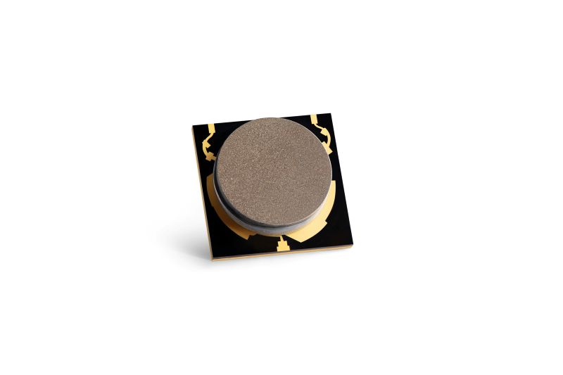
Microstrip circulators are selected for high-density RF modules, compact communication equipment, and PCB-integrated architectures. Board stack-up, grounding, and nearby metal structures influence performance; layout discipline is part of the design.
Product pathway: Microstrip RF Circulator
5.3 Ferrite junction core (internal performance driver)
The junction region is where bandwidth, isolation, and IL are “made.” Tight tolerance control and stable magnetic bias are key for consistent performance across production lots—especially for wideband or temperature-rated designs.
5.4 Drop-in RF Circulator & Waveguide Circulator
Drop-in circulators are used for embedded integration and compact assembly. Waveguide circulators provide strong thermal/mechanical headroom for high-power and millimeter-wave applications.
Product pathways: Drop-in RF Circulator | Waveguide Circulator
6) Parameter Comparison Tables (Structure + Band + Power Planning)
The tables below provide engineering-oriented reference ranges. Actual performance depends on frequency band, bandwidth, power level, mechanical interface, PCB environment (for microstrip), and qualification conditions. Use these tables to narrow the right structure type first, then confirm band-specific targets and mismatch (VSWR) expectations.
6.1 Structure-level Comparison (Most practical starting point)
| Structure Type | Best Fit / Typical Use | Common Frequency Use | Typical Bandwidth Style | Typical Insertion Loss (IL) | Typical Isolation | Typical VSWR | Power Handling Tendency | Main Risks / Watch-outs | HzBeat Product Path |
|---|---|---|---|---|---|---|---|---|---|
| Microstrip RF Circulator | PCB integration, compact modules, high-density RF front-ends | L/S/C/X/Ku and some mmWave (design dependent) | Often wideband with layout-dependent edges | ~0.3–0.9 dB (band & PCB dependent) | ~18–25 dB+ (response shape matters) | ≤1.3 typical (edge can drift with PCB) | Low–mid power (thermal path limited by PCB) | PCB stack-up/grounding/shielding changes S-parameters; keep metal clearance rules | Microstrip RF Circulator |
| Drop-in RF Circulator | Embedded assemblies, compact packaging, system integration | Broad coverage (series dependent) | Moderate to wideband (depending on matching network) | ~0.3–1.0 dB | ~18–25 dB+ | ≤1.3–1.5 typical | Mid power variants available | Mounting flatness + thermal interface dominates reliability; verify termination power path | Drop-in RF Circulator |
| Coaxial RF Circulator | Connectorized systems, lab setups, modular RF chains | Common across many GHz ranges | Often wideband; very stable in fixtures | ~0.2–0.7 dB | ~18–25 dB+ (some designs higher at center) | ≤1.3 typical | Mid–high power possible (design/connector dependent) | Connector quality & torque control; verify peak power and reflected power rating | Coaxial RF Circulator |
| Waveguide Circulator | High power radar, mmWave, strong thermal headroom | Band-defined by waveguide (X/Ku/Ka/mmWave typical) | Band-limited, high robustness | Often low–moderate (band & design dependent) | Often strong isolation across waveguide band | Waveguide match depends on flange + assembly | High power capability (radar-grade) | Flange alignment/surface finish/gasket; mechanical tolerance drives repeatability | Waveguide Circulator |
6.2 Band-level Targets (Typical windows engineers use for planning)
Band targets vary by structure. This table is most useful for setting initial expectations and deciding what to prioritize (loss vs isolation vs bandwidth vs power).
| Band | Common Use | Preferred Structures | Typical Bandwidth Expectation | Typical IL Window | Typical Isolation Window | Typical VSWR Window | Common Pain Points |
|---|---|---|---|---|---|---|---|
| L (1–2 GHz) | Telemetry, navigation, some radar chains | Coaxial / Drop-in / Microstrip | Moderate to wide (spec-driven) | ~0.2–0.7 dB | ~18–25 dB+ | ≤1.3–1.5 | Wide bandwidth requests push matching complexity; size can grow for high power |
| S (2–4 GHz) | Radar, comms, RF front-ends | Microstrip / Coaxial / Drop-in | Often wideband in modern systems | ~0.25–0.8 dB | ~18–25 dB+ | ≤1.3–1.5 | Mismatch events can dominate; keep isolation consistency across band edges |
| C (4–8 GHz) | Radar + SATCOM subsystems | Microstrip / Coaxial / Waveguide (high power) | Wideband often requested | ~0.3–0.9 dB | ~18–25 dB+ | ≤1.3–1.5 | Edge ripple and IL growth at band edges; thermal rise at higher power |
| X (8–12 GHz) | Classic radar, high reliability chains | Waveguide / Coaxial / Microstrip (module) | Band-limited to moderate | ~0.3–1.0 dB | ~18–25 dB+ | ≤1.3–1.6 | Power + thermal + mechanical consistency; flange/connector integrity matters |
| Ku (12–18 GHz) | SATCOM, radar modules | Waveguide / Microstrip / Coaxial | Moderate (application-driven) | ~0.4–1.2 dB | ~18–25 dB+ | ≤1.4–1.8 | Loss sensitivity rises; layout and shielding become major factors for PCB designs |
| Ka (26–40 GHz) | SATCOM, mmWave links, radar | Waveguide / Microstrip (advanced) / Coaxial (limited) | Often narrower, band-defined | ~0.6–1.8 dB | ~18–25 dB+ (often shaped response) | ≤1.6–2.0 | Assembly precision, surface finish, and thermal design dominate stability |
| mmWave (40+ GHz) | Radar, high-frequency links, advanced front-ends | Waveguide / Specialized microstrip | Band-defined (tight tolerance) | ~1.0–3.0 dB (varies strongly) | ~18–25 dB+ (depends on band & design) | ≤1.8–2.5 | Mechanical tolerances, flange alignment, and measurement uncertainty become dominant |
6.3 Power & Termination Planning (Reflected power is the real test)
| Question | Why it matters | What to specify in RF circulator inquiry | Practical recommendation |
|---|---|---|---|
| What VSWR can the antenna/load reach? | Reflected power under mismatch can exceed what the PA/circulator can safely dissipate | Worst-case VSWR (or return loss), frequency band, duty cycle | Design for the worst realistic mismatch, not the lab 50 Ω condition |
| How is Port-3 terminated? | Port-3 load must absorb reflected energy; under high mismatch it can become the thermal bottleneck | Termination type, rated power, mounting method, cooling | Ensure termination power rating exceeds reflected power scenario with margin |
| Is the thermal interface defined? | Mounting flatness, torque, and heatsink affect temperature rise and drift | Mounting surface, torque spec, thermal grease or pad details | Treat thermal interface as part of the RF design, not an afterthought |
| What is the verification plan? | Different test fixtures and calibration approaches can produce different results | Test temperature points, calibration, bandwidth sweep, power level | Confirm measurement conditions match your application requirements |
7) Frequency Bands & Practical Notes
HzBeat RF circulator solutions span wide frequency coverage (20 MHz–200 GHz). Practical selection is typically band-driven:
- L band (1–2 GHz): telemetry, navigation, selected radar chains; wideband matching strategy affects edge performance.
- S band (2–4 GHz): radar/communications; isolation margin helps with antenna mismatch.
- C band (4–8 GHz): radar and SATCOM; wideband designs require careful impedance transitions.
- X band (8–12 GHz): classic radar band; thermal and power considerations become prominent.
- Ku/Ka band: SATCOM modules; insertion loss sensitivity increases; mechanical repeatability matters.
- mmWave: surface finish, assembly precision, and mechanical interfaces dominate performance stability.
When pursuing ultra-wideband coverage and miniaturization, it is important to evaluate not only center frequency performance, but also band-edge behavior, ripple, and temperature drift.
8) High-Power & Thermal Reliability
8.1 Reflections are often the limiting case
Many lab benches use well-matched loads. Field conditions rarely do. Antenna detuning, cable movement, connector wear, and environmental variation can raise VSWR and increase reflected power. A high-power RF circulator must tolerate these mismatch events without performance collapse or drift.
8.2 Thermal interface is a system design parameter
Heat extraction depends on mounting flatness, torque control, contact area, and heatsink quality. A strong device can still underperform if the thermal interface is poor. For high-power systems, consider thermal path early rather than after qualification problems appear.
Related topic: RF Circulator Failure Analysis
9) Engineering Cases (Real Integration)
Below are common engineering scenarios where RF circulators are deployed. These cases translate datasheet parameters into practical integration decisions.
Case A: PA Protection in a Transmitter Chain (Mismatch Events)
Scenario: PA output feeds an antenna that can experience mismatch (movement, icing, proximity effects, or wideband antenna variation). Reflected power returns toward the PA, risking gain compression, instability, or failure.
Integration pattern: PA → RF Circulator → Antenna, with the third port routed to a matched load/termination.
- Key spec: Isolation across the band
- Key spec: Reflected power handling
- Key spec: IL (thermal)
- Key spec: VSWR stability
HzBeat structure guidance: For connectorized modular systems, a Coaxial RF Circulator is commonly selected. For embedded modules, consider Drop-in RF Circulator with verified thermal interface and termination power margin.
Case B: Radar T/R Front-End (Peak Power + Temperature Cycling)
Scenario: Pulsed radar chains experience high peak power and rapid thermal transitions. Reflections from the antenna and duplexing architecture require robust non-reciprocal routing.
Engineering focus: Maintain isolation and IL stability under temperature variation and peak power stress.
- Key spec: Peak power margin
- Key spec: Thermal cycling stability
- Key spec: Isolation consistency
- Key spec: Mechanical interface quality
HzBeat structure guidance: For higher power and stronger thermal headroom, consider Waveguide Circulator when mechanical format allows.
Case C: Test & Measurement Bench (Repeatability and Instrument Protection)
Scenario: In VNA or measurement setups, DUT impedance changes can reflect power and distort results. A circulator can protect sensitive instrument ports and improve repeatability.
Integration pattern: Source/PA → RF Circulator → DUT, with the third port terminated to absorb reflections.
- Key spec: Low ripple
- Key spec: Consistent match
- Key spec: Mechanical repeatability
- Key spec: Connector quality
HzBeat structure guidance: A connectorized Coaxial RF Circulator is typically the most convenient option for bench workflows.
10) Selection Guide (Step-by-Step)
Step 1: Define band & bandwidth
Identify operating band and required bandwidth, including guard margins. Evaluate performance across the full band, not just the center frequency.
Step 2: Define power + mismatch scenario
Specify CW and peak power and the mismatch expectation (VSWR / return loss) in field conditions. For many systems, mismatch events determine the design limit.
Step 3: Choose the structure type
- Microstrip RF Circulator: PCB integration and miniaturization.
- Drop-in RF Circulator: embedded modules and compact assembly.
- Coaxial RF Circulator: connectorized integration and repeatable test setups.
- Waveguide Circulator: high power and mmWave, strong thermal headroom.
Step 4: Set parameter priorities
Decide what dominates your system: lowest IL, widest band, highest isolation, smallest size, or highest power. This avoids selecting parts that look great on a single spec line but struggle in integration.
Step 5: Confirm verification method
Request measurement coverage across band and temperature points if required. Ask for fixture repeatability and calibration references where possible.
11) RFQ Checklist (What to Provide for Fast, Accurate Quoting)
If you send the checklist below in your inquiry, the selection and quotation process becomes much faster and the recommended configuration will match your real system conditions more closely.
- Application: radar / SATCOM / 5G/6G / test bench / other (brief system description)
- Frequency range: start–stop frequency, and the required usable bandwidth (include guard margins)
- Target specifications: insertion loss (IL) target and max, isolation target and min, VSWR/return loss target
- Power requirements: CW power, peak power, duty cycle, pulse width (if pulsed)
- Mismatch / reflection scenario: worst-case VSWR (or return loss), and whether mismatch events are expected in the field
- Termination plan (Port-3): internal or external load, load power rating, mounting/cooling method
- Structure preference: Microstrip / Drop-in / Coaxial / Waveguide (or ask for recommendation)
- Mechanical interface: connector type (SMA/N/others), waveguide standard/flange type, or PCB footprint constraints
- Size constraints: maximum envelope (L×W×H) and mounting hole pattern if required
- Direction: clockwise or counter-clockwise (or “either acceptable”)
- Operating environment: temperature range (e.g., -55°C to +85°C), vibration/shock, humidity if relevant
- Verification needs: test points (temperature), measurement method requirements, documentation needs (e.g., COC, test report)
- Quantity & schedule: prototype quantity, expected production volume, target lead time
- Compliance / special requirements: any material constraints, export restrictions, or customer-specific qualification plan
12) Manufacturing & Quality Control (Process Evidence)
Performance consistency is tied to process control. For wideband or temperature-rated designs, manufacturing discipline becomes a primary quality driver: ferrite preparation, machining tolerances, magnetic bias calibration, and RF verification together determine whether a design behaves predictably in real systems.
12.1 Typical controls used in production verification
- Ferrite material control: stable magnetic properties and loss profile.
- Precision machining: geometry tolerance that preserves matching and isolation distribution.
- Magnetic bias calibration: consistent bias point for non-reciprocal behavior.
- VNA S-parameter testing: repeatable fixtures and band coverage verification.
- Thermal validation: performance checks at temperature extremes when required.
- High-power stress verification: evaluation under power and mismatch-like conditions when applicable.
13) FAQ
What is the difference between an RF circulator and an RF isolator?
An RF isolator is commonly a circulator used as a two-port device by terminating one port with a matched load. Circulators provide three-port routing flexibility, while isolators focus on one-way protection.
What insertion loss is considered good for an RF circulator?
Typical high-quality designs often target ~0.2–0.6 dB depending on band and structure. Acceptability depends on your thermal budget, link margin, and stability requirements.
How much isolation do I need?
Many systems use 18–25 dB+ isolation depending on mismatch risk and PA sensitivity. If your antenna environment is unstable, prioritize isolation consistency across the entire band.
Do RF circulators need external DC power?
No. Most ferrite circulators use permanent magnets for bias and require no external power supply.
Can RF circulators operate from -55°C to +85°C?
Yes—industrial designs can be engineered and verified across that range, depending on configuration and qualification requirements.
Related Articles & Internal Links
These internal links are designed to reinforce topical authority and help users move from fundamentals → selection → product structures.
Contact HzBeat
For custom frequency bands, higher power requirements, tighter IL/Isolation targets, or miniaturized integration, contact our engineering team to discuss selection and configuration options.
- Email: [email protected]
- WhatsApp: +86-15388440404
- Website: https://www.hzbeat.com
Recommended Products


.jpg)

Sara
Sara is a Brand Specialist at Hzbeat, focusing on RF & microwave industry communications. She transforms complex technologies into accessible insights, helping global readers understand the value of circulators, isolators, and other key components.