Difference Between Isolator and Circulator in Microwave
Updated on:
Keywords: Difference Between Isolator and Circulator, microwave isolator, microwave circulator, RF isolator vs circulator
1. Introduction
Modern RF systems—from 5G macro sites and phased‑array radar to satellite communications—depend on non‑reciprocal devices to control energy flow and protect sensitive stages. Two core components are the microwave circulator and the microwave isolator. They share ferrite physics but differ in topology, function, and integration strategy.

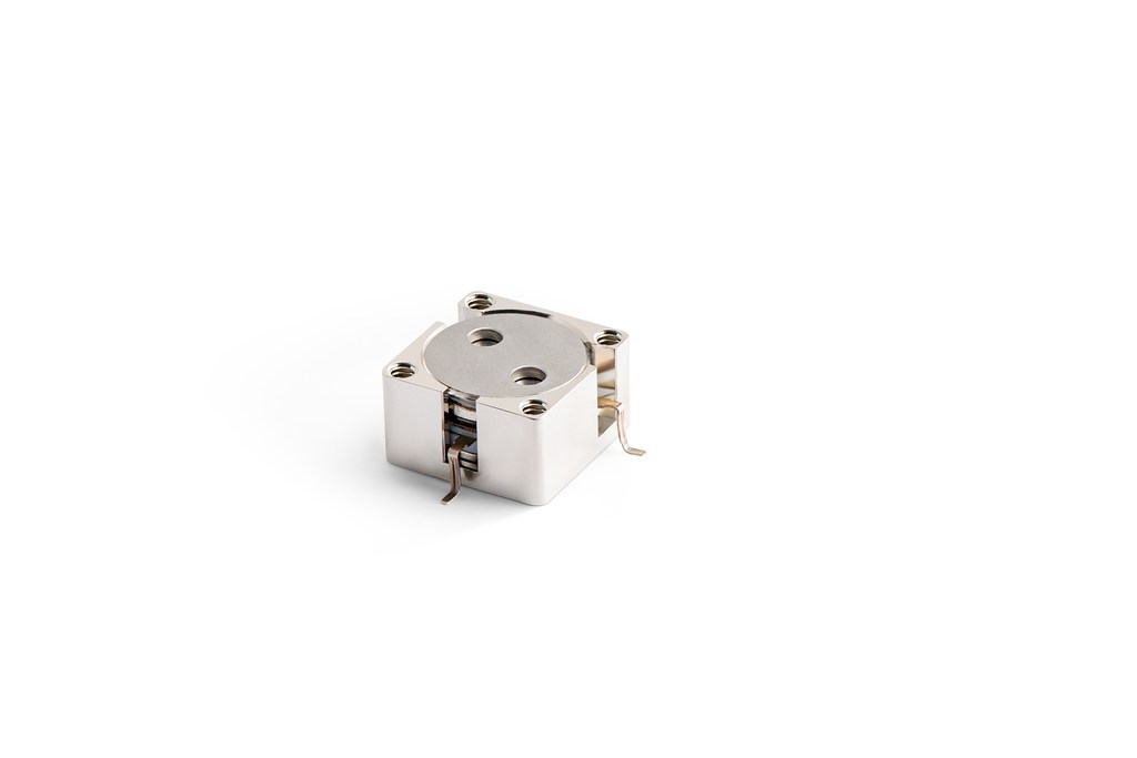
HzBeat product photo: Drop‑in microwave circulator / isolator for high‑power front‑ends. Photo © HzBeat.
2. Definitions & S‑Matrix
2.1 Microwave Circulator
A microwave circulator is a three‑port non‑reciprocal network that routes energy sequentially—1→2, 2→3, 3→1. The ideal 3‑port scattering matrix is:
S = [[0, 0, 1], [1, 0, 0], [0, 1, 0]]
Practical devices exhibit finite insertion loss, finite isolation, limited bandwidth, and power/temperature dependencies.
2.2 Microwave Isolator
A microwave isolator is a two‑port non‑reciprocal device: low loss in the forward direction, strong attenuation in the reverse direction. Many isolators are realized by terminating the third port of a circulator with a matched load—converting a 3‑port network into a robust 2‑port protector.
3. Theoretical Background & Ferrite Physics
Both devices exploit gyromagnetic anisotropy in ferrites under DC bias. The magnetized ferrite exhibits a permeability tensor (Polder model), making propagation constants different for counter‑rotating field components. In junction circulators, modal interference and boundary conditions enforce directional phase advance; in isolators, Faraday rotation plus a resistive termination dissipate reverse power. Understanding these fundamentals clarifies why a microwave circulator can be turned into a microwave isolator by proper termination.
4. Construction & Operating Principles
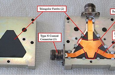
Common architectures include Y‑junction ferrite discs, stripline/microstrip implementations, and waveguide resonant structures. Performance hinges on ferrite composition, magnet bias uniformity, mechanical tolerances, and thermal design. In an RF isolator, the termination network must maintain match across temperature; in a microwave circulator, symmetry and alignment keep port‑to‑port isolation consistent.
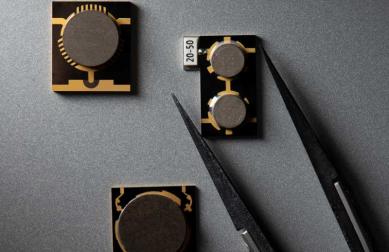
HzBeat product photo: Microstrip/SMT‑style circulator for compact modules. Photo © HzBeat.
5. Packaging Formats
Waveguide circulator
Low IL, high CW/PK power, suited for X/Ku/Ka bands; larger size and mass. Typical in radar and gateway equipment.
Coaxial circulator / isolator
Connectorized convenience for lab/test and moderate‑power links; manage PIM via torque and cleanliness.
Drop‑in circulator
Favored in T/R modules; requires flat mounting, controlled screw torque, and reliable thermal interface materials.
Microstrip / SMT circulator
Compact footprints for FR1 and dense modules; layout shielding and heat‑spreaders are critical.
6. Circulator vs Isolator: Key Differences
| Aspect | Microwave Circulator | Microwave Isolator |
|---|---|---|
| Topology | 3‑port (or 4‑port) non‑reciprocal network | 2‑port non‑reciprocal (often circulator + termination) |
| Function | Directional routing: 1→2→3→1; duplexing without switching | Unidirectional protection: forward low‑loss, reverse power absorbed |
| Insertion loss | Slightly higher than isolator for same band/package | Forward IL minimized for PA efficiency |
| Isolation | Between specific port pairs; geometry‑dependent | Reverse direction isolation maximized |
| Preferred scenarios | T/R modules, antenna sharing, radar front‑ends | PA output protection, test benches, measurement stability |
| Packaging | Waveguide / Coaxial / Drop‑in / Microstrip / SMT | Same family; simpler two‑port interconnect |
| Cost/complexity | Higher (extra port and routing constraints) | Lower (two ports + termination) |
7. Critical Specs (IL, Isolation, VSWR, Power)
- Insertion Loss (IL): minimize across band; waveguide is best for low IL; SMT trades IL for size and integration.
- Isolation: telecom targets ≥18–22 dB; radar/SatCom often ≥20–25 dB+. Isolation degrades with temperature and bias drift.
- VSWR / Return Loss: connector quality (coaxial) and PCB layout (microstrip) dominate matching; poor VSWR raises PA stress.
- Power handling: distinguish CW vs peak; consider altitude/temperature derating; pressurized waveguide helps at high altitude.
- Linearity / IMD: for high‑linearity links, low PIM assembly and clean interfaces are essential.
- Temperature range: typical −40 °C to +85 °C or wider; check isolation drift versus temperature.
Rule‑of‑thumb:
FR1 microstrip/coaxial links often target IL ≤0.4–0.6 dB and isolation ≥18–22 dB; X/Ku/Ka gateways prefer waveguide for lower IL and higher power headroom.
8. Measurement & Characterization
Characterize microwave circulator and microwave isolator using a calibrated VNA (full 2‑port for isolators, 3‑port sequential for circulators). Recommended steps:
- Perform SOLT or TRL calibration across intended band.
- Measure forward S‑parameters (S21) and reverse isolation (S12) under nominal bias/temperature.
- Stress test with elevated VSWR at output to verify stability and protection behavior.
- Record IL/Isolation versus temperature; watch for magnet bias drift.
For power handling, use a controlled RF source with power meter and dummy load; monitor case temperature and isolate failure modes (thermal, arcing, connector degradation).
9. Reliability & Standards (IEC/MIL/GB)
- Environmental: IEC 60068 thermal cycling, vibration, shock; MIL‑STD‑202 methods for component‑level stress.
- RoHS/REACH: material declarations for global trade compliance.
- Salt‑spray / humidity: for outdoor telecom; check enclosure plating and sealing quality.
- Qualification: isolation retention after thermal cycles; VSWR under load; power survivability at specified mismatch (e.g., 2:1, 3:1).
Documented reliability builds purchasing confidence and reduces field failures in large‑scale rollouts.
10. Design & Simulation Workflow
- Target definition: band, IL, isolation, VSWR, CW/PK power, temperature, size.
- Ferrite & magnetics: select composition and bias scheme; simulate permeability tensor response.
- Electromagnetics (EM): 3D EM modeling of junction/guide; extract S‑parameters.
- Thermal/mechanical: simulate heat paths, flatness, screw patterns; define torque specs.
- Prototype & tune: build, measure, iterate; control bias uniformity and termination match.
- DFM/Scale‑up: process capability, SPC on IL/Isolation; define acceptance criteria.
11. Selection Guide by Scenario
| Scenario | Recommended device | Why | Notes |
|---|---|---|---|
| PA protection in 5G macro/small cell | Microwave isolator | Absorbs reflections, stabilizes PA, minimal IL | Place right after PA; ensure load rating and thermal path |
| T/R module duplexing (radar) | Drop‑in circulator | Routes TX→ANT and RX←ANT without switch loss | Mounting flatness and bias uniformity matter |
| SatCom gateway (Ku/Ka) | Waveguide circulator | Lowest IL and high power headroom | Consider pressurization at altitude |
| Lab/test benches | Isolator or circulator + termination | Improves match and repeatability | Calibrate VNA carefully; manage connector wear |
Explore products: Microstrip Circulator · Drop‑in Circulator
Quick rule:
Need routing (shared antenna, T/R)? → choose a microwave circulator. Need protection (PA output, test bench)? → choose a microwave isolator.
12. China‑Focused Procurement & Supply Chain
For China deployments, prioritize lead time, MOQ, customization (band, isolation, package), and local service. Domestic manufacturers offering rapid prototyping, bilingual documentation, and engineering support often win integrated‑system bids.
- Define acceptance tests (IL/Isolation vs temp) in PO to avoid ambiguity.
- Ask for SPC snapshots on critical characteristics (IL, isolation, VSWR).
- Ensure spare loads for isolators are rated for worst‑case reflected power.
13. Case Studies
Case A — 5G PA Protection
In a macro base station, a high‑power LDMOS PA drives the feeder. An RF isolator immediately after the PA absorbs reverse power due to antenna mismatch, protecting the amplifier and improving stability. A circulator could work, but it adds cost/size without routing benefits.
Case B — Phased‑Array Radar T/R
A drop‑in circulator with ports to PA, antenna, and LNA provides duplex operation per element. Phase stability, thermal design, and mounting flatness are decisive for maintaining isolation and gain balance across the array.
Case C — SatCom Gateway Ku/Ka
Gateways prefer waveguide circulator for low IL and high power headroom; terminals may use coaxial or compact microstrip units to reduce mass and volume while accepting higher IL.
14. FAQ
Q1. Can a circulator be used as an isolator?
Yes—terminate the third port with a matched load to convert a 3‑port circulator into a 2‑port microwave isolator.
Q2. Which has lower insertion loss?
At comparable conditions, an isolator typically achieves lower forward IL because it optimizes a single direction with termination.
Q3. Which is better for high power?
Waveguide circulator/isolator dominate where CW/PK power headroom is critical; coaxial and SMT serve compact/moderate‑power roles.
Q4. How to pick for FR2 (mmWave)?
Balance IL vs footprint; consider microstrip/SMT circulator for compact modules, but use waveguide circulator for gateways needing headroom.
Q5. What reliability tests should I ask for?
Thermal cycling (IEC 60068), vibration/shock (MIL‑STD‑202 methods), salt‑spray/humidity for outdoor telecom, and isolation retention after cycles.
Talk to an engineer
Need help choosing a microwave isolator and a microwave circulator? Share band, CW/PK power, IL/Isolation targets, and preferred package (waveguide, coaxial, drop‑in, microstrip/SMT).
Relateds


About the Author

HzBeat Editorial Content Team
Marketing Director, Chengdu Hertz Electronic Technology Co., Ltd. (Hzbeat)
Keith has over 18 years in the RF components industry, focusing on the intersection of technology, healthcare applications, and global market trends.