Home/ Coaxial Circulator/ High Power Coaxial Circulator
High Power Coaxial Circulator
L Band ,S Band, C Band, X Band, Ku Band, K Band, Ka Band
- High Power Coaxial Circulator is a crucial component in RF and microwave systems, specifically designed to handle high power levels while providing efficient signal routing and isolation within a coaxial transmission line.
Key Features & Advantages
- High power capacity supporting high peak power (tens of kilowatts to several megawatts) and high average power (hundreds of watts to several kilowatts), making it suitable for radar, broadcasting, communication base stations, and industrial heating systems.
- Low insertion loss minimizes forward signal energy loss, improving system efficiency while reducing energy waste and heat generation.
- High isolation prevents reflected signals from returning to the source, protecting core active devices such as power amplifiers.
- High stability and reliability with a fully sealed structure resistant to moisture, salt spray, and mold, wide operating temperature range (e.g., -55°C to +85°C), and strong power tolerance for long-term stable operation in harsh environments.
- Excellent Voltage Standing Wave Ratio (VSWR): Low VSWR (typically < 1.5) ensures good matching with transmission lines, reduces signal reflections, and guarantees signal integrity.
Typical Applications
- Radar systems: Connects the transmitter and antenna, directing high-power pulses during transmission and weak echo signals during reception while isolating transmit pulses to protect sensitive receiver circuits as a core T/R switch component.
- Mobile communication base stations: Placed between the PA and antenna, directing amplified signals for transmission and received signals to the LNA while isolating reflections to prevent PA damage from mismatch.
- Broadcast transmitter systems (FM/TV): Used in power combining to merge multiple amplifier outputs and isolate reflected power, ensuring transmitter stability and efficiency.
- Industrial heating & medical equipment: Used in microwave energy applications such as ovens, plasma generators, and MRI systems, protecting the source or amplifier from load variations.
- Scientific Research: Used in high-power experimental setups like particle accelerators, NMR, and plasma research.
Electrical Performance Table and Product Appearance
0.1~0.4GHz High Power Coaxial Circulator
Product Overview
The following products are case examples of VHF~UHF-band High Power Coaxial Circulators. Product dimensions and port configurations can be customized based on high-power requirements and high reflected power.
Model
Frequency(GHz)
BW Max
Insertion loss(dB) Max
Isolation(dB)Min
VSWR Max
Connector
operating temperature(℃)
PK/CW/RP(Watt)
Direction
HCCTA01T04G⬇
0.1~0.4
10%
0.4
20
1.2
N-K
-55~+85℃
5000/500
Clockwise
HCCTB01T04G⬇
0.1~0.4
10%
0.4
20
1.2
N-K
-55~+85℃
5000/500
Counter Clockwise
0.2~0.6GHz High Power Coaxial Circulator
Product Overview
The following products are case examples of VHF to UHF band High Power Coaxial Circulators. Product dimensions and port configurations can be customized based on high-power requirements and high reflected power.
Model
Frequency(GHz)
BW Max
Insertion loss(dB) Max
Isolation(dB)Min
VSWR Max
Connector
operating temperature(℃)
PK/CW/RP(Watt)
Direction
HCCTA02T06G⬇
0.2~0.6
10%
0.4
20
1.2
N-K
-55~+85℃
3000/300
Clockwise
HCCTB02T06G⬇
0.2~0.6
10%
0.4
20
1.2
N-K
-55~+85℃
3000/300
Counter Clockwise
0.4~1.0GHz High Power Coaxial Circulator
Product Overview
The following products are case examples of UHF-band High Power Coaxial Circulators. Product dimensions and port configurations can be customized based on high-power requirements and high reflected power.
Model
Frequency(GHz)
BW Max
Insertion loss(dB) Max
Isolation(dB)Min
VSWR Max
Connector
operating temperature(℃)
PK/CW/RP(Watt)
Direction
HCCTA04T10G⬇
0.4~1.0
10%
0.4
20
1.2
N-K
-55~+85℃
2000/200
Clockwise
HCCTB04T10G⬇
0.4~1.0
10%
0.4
20
1.2
N-K
-55~+85℃
2000/200
Counter Clockwise
0.8~2.5GHz High Power Coaxial Circulator
Product Overview
The following products are case examples of UHF to S band High Power Coaxial Circulators.Product dimensions and port configurations can be customized based on high-power requirements and high reflected power.
Model
Frequency(GHz)
BW Max
Insertion loss(dB) Max
Isolation(dB)Min
VSWR Max
Connector
operating temperature(℃)
PK/CW/RP(Watt)
Direction
HCCTA08T25G⬇
0.8~2.5
10%
0.4
20
1.2
N-K
-55~+85℃
1500/150
Clockwise
HCCTB08T25G⬇
0.8~2.5
10%
0.4
20
1.2
N-K
-55~+85℃
1500/150
Counter Clockwise
2.0~4.0GHz High Power Coaxial Circulator
Product Overview
The following products are S-band broadband high-power coaxial circulators, designed using high-power materials and improved heat dissipation solutions.
Model
Frequency(GHz)
BW Max
Insertion loss(dB) Max
Isolation(dB)Min
VSWR Max
Connector
operating temperature(℃)
PK/CW/RP(Watt)
Direction
HCCTA20T40G⬇
2.0~4.0
FULL
0.8
15.0
1.5
N-K
-40~+70
-/500
Clockwise
HCCTB20T40G⬇
2.0~4.0
FULL
0.8
15.0
1.5
N-K
-40~+70
-/500
Counter Clockwise
About HzBeat
HzBeat is a leading RF component manufacturer specializing in RF circulators and isolators, as a global supplier of RF circulators and isolators (20MHz–200GHz), we providing microstrip, drop-in, coaxial, and waveguide solutions for communication systems, radar, satellite, and medical imaging.
For detailed technical documentation, sample requests, or customization needs, please do not hesitate to contact us. — we respond within 24 hours to ensure you get precise solutions for your design.
Customization & Selection Guide
- Operating Band:Ensure it covers all frequencies required by your system.
- Power Handling Capacity:Select based on your system's transmit power (average and peak), allowing a certain margin.
- Performance Requirements:Define specific requirements for Insertion Loss, Isolation, and VSWR/Return Loss.
- Environmental Conditions:Consider operating temperature range, vibration, humidity, etc.
- Cost & Delivery:Balance cost and project timeline while meeting performance requirements.
Why Choose Our Product
- Profound Technical Expertise:We have over 18 years of R&D experience in ferrite materials and microwave magnetics.
- Fully Automated Production Lines:Ensure consistent excellence and reliability in every unit.
- Professional Application Support:Our engineering team provides timely technical selection, customization, and failure analysis services.
- Competitive Pricing & Lead Times:Economies of scale from mass production enable us to respond quickly to your orders.
Related Products
Questions? Feel Free to Reach Out Via Message.
Tell us frequency band, target IL/Isolation/VSWR, power level and timeline — we’ll match the best topology and deliver S-parameters.We will contact you within 24 hours.
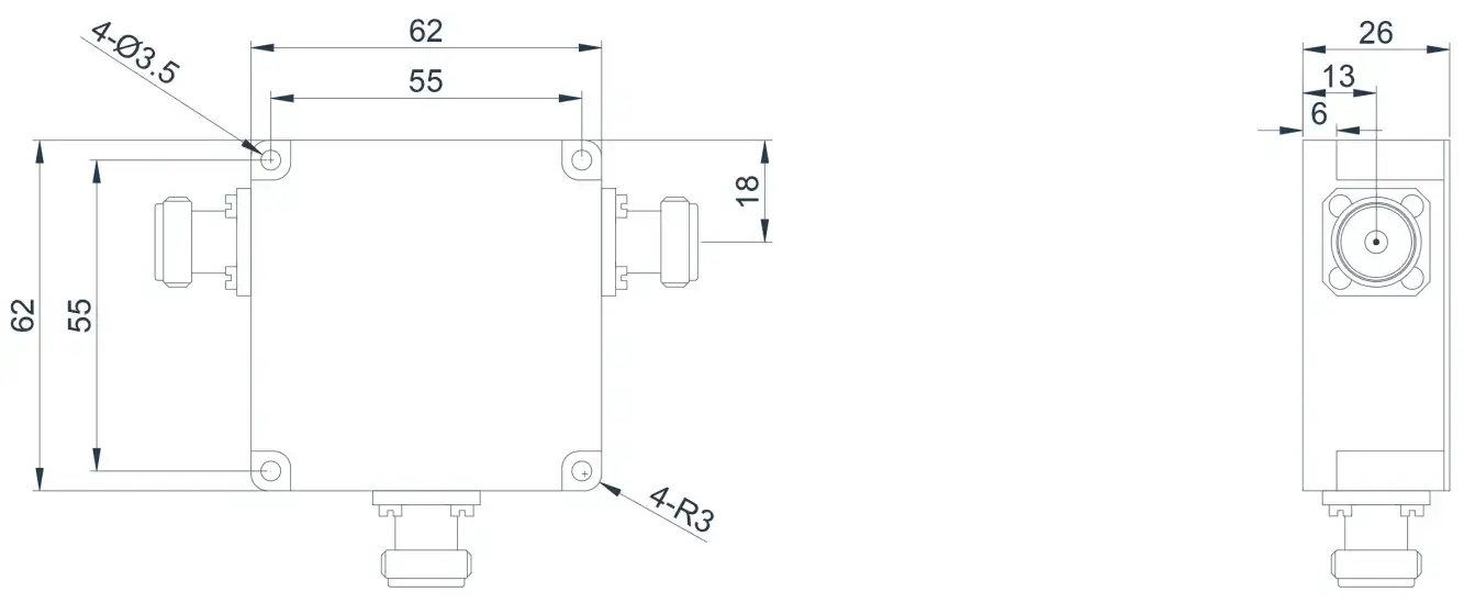
Product Overview
The following products are case examples of VHF~UHF-band High Power Coaxial Circulators. Product dimensions and port configurations can be customized based on high-power requirements and high reflected power.
| Model | Frequency(GHz) | BW Max | Insertion loss(dB) Max | Isolation(dB)Min | VSWR Max | Connector | operating temperature(℃) | PK/CW/RP(Watt) | Direction |
|---|---|---|---|---|---|---|---|---|---|
| HCCTA01T04G⬇ | 0.1~0.4 | 10% | 0.4 | 20 | 1.2 | N-K | -55~+85℃ | 5000/500 | Clockwise |
| HCCTB01T04G⬇ | 0.1~0.4 | 10% | 0.4 | 20 | 1.2 | N-K | -55~+85℃ | 5000/500 | Counter Clockwise |
0.2~0.6GHz High Power Coaxial Circulator
Product Overview
The following products are case examples of VHF to UHF band High Power Coaxial Circulators. Product dimensions and port configurations can be customized based on high-power requirements and high reflected power.
Model
Frequency(GHz)
BW Max
Insertion loss(dB) Max
Isolation(dB)Min
VSWR Max
Connector
operating temperature(℃)
PK/CW/RP(Watt)
Direction
HCCTA02T06G⬇
0.2~0.6
10%
0.4
20
1.2
N-K
-55~+85℃
3000/300
Clockwise
HCCTB02T06G⬇
0.2~0.6
10%
0.4
20
1.2
N-K
-55~+85℃
3000/300
Counter Clockwise
0.4~1.0GHz High Power Coaxial Circulator
Product Overview
The following products are case examples of UHF-band High Power Coaxial Circulators. Product dimensions and port configurations can be customized based on high-power requirements and high reflected power.
Model
Frequency(GHz)
BW Max
Insertion loss(dB) Max
Isolation(dB)Min
VSWR Max
Connector
operating temperature(℃)
PK/CW/RP(Watt)
Direction
HCCTA04T10G⬇
0.4~1.0
10%
0.4
20
1.2
N-K
-55~+85℃
2000/200
Clockwise
HCCTB04T10G⬇
0.4~1.0
10%
0.4
20
1.2
N-K
-55~+85℃
2000/200
Counter Clockwise
0.8~2.5GHz High Power Coaxial Circulator
Product Overview
The following products are case examples of UHF to S band High Power Coaxial Circulators.Product dimensions and port configurations can be customized based on high-power requirements and high reflected power.
Model
Frequency(GHz)
BW Max
Insertion loss(dB) Max
Isolation(dB)Min
VSWR Max
Connector
operating temperature(℃)
PK/CW/RP(Watt)
Direction
HCCTA08T25G⬇
0.8~2.5
10%
0.4
20
1.2
N-K
-55~+85℃
1500/150
Clockwise
HCCTB08T25G⬇
0.8~2.5
10%
0.4
20
1.2
N-K
-55~+85℃
1500/150
Counter Clockwise
2.0~4.0GHz High Power Coaxial Circulator
Product Overview
The following products are S-band broadband high-power coaxial circulators, designed using high-power materials and improved heat dissipation solutions.
Model
Frequency(GHz)
BW Max
Insertion loss(dB) Max
Isolation(dB)Min
VSWR Max
Connector
operating temperature(℃)
PK/CW/RP(Watt)
Direction
HCCTA20T40G⬇
2.0~4.0
FULL
0.8
15.0
1.5
N-K
-40~+70
-/500
Clockwise
HCCTB20T40G⬇
2.0~4.0
FULL
0.8
15.0
1.5
N-K
-40~+70
-/500
Counter Clockwise
About HzBeat
HzBeat is a leading RF component manufacturer specializing in RF circulators and isolators, as a global supplier of RF circulators and isolators (20MHz–200GHz), we providing microstrip, drop-in, coaxial, and waveguide solutions for communication systems, radar, satellite, and medical imaging.
For detailed technical documentation, sample requests, or customization needs, please do not hesitate to contact us. — we respond within 24 hours to ensure you get precise solutions for your design.
Customization & Selection Guide
- Operating Band:Ensure it covers all frequencies required by your system.
- Power Handling Capacity:Select based on your system's transmit power (average and peak), allowing a certain margin.
- Performance Requirements:Define specific requirements for Insertion Loss, Isolation, and VSWR/Return Loss.
- Environmental Conditions:Consider operating temperature range, vibration, humidity, etc.
- Cost & Delivery:Balance cost and project timeline while meeting performance requirements.
Why Choose Our Product
- Profound Technical Expertise:We have over 18 years of R&D experience in ferrite materials and microwave magnetics.
- Fully Automated Production Lines:Ensure consistent excellence and reliability in every unit.
- Professional Application Support:Our engineering team provides timely technical selection, customization, and failure analysis services.
- Competitive Pricing & Lead Times:Economies of scale from mass production enable us to respond quickly to your orders.
Related Products
Questions? Feel Free to Reach Out Via Message.
Tell us frequency band, target IL/Isolation/VSWR, power level and timeline — we’ll match the best topology and deliver S-parameters.We will contact you within 24 hours.
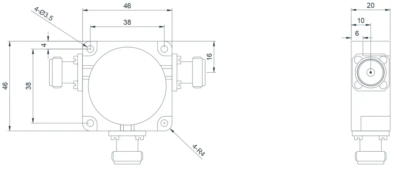
Product Overview
The following products are case examples of VHF to UHF band High Power Coaxial Circulators. Product dimensions and port configurations can be customized based on high-power requirements and high reflected power.
| Model | Frequency(GHz) | BW Max | Insertion loss(dB) Max | Isolation(dB)Min | VSWR Max | Connector | operating temperature(℃) | PK/CW/RP(Watt) | Direction |
|---|---|---|---|---|---|---|---|---|---|
| HCCTA02T06G⬇ | 0.2~0.6 | 10% | 0.4 | 20 | 1.2 | N-K | -55~+85℃ | 3000/300 | Clockwise |
| HCCTB02T06G⬇ | 0.2~0.6 | 10% | 0.4 | 20 | 1.2 | N-K | -55~+85℃ | 3000/300 | Counter Clockwise |
0.4~1.0GHz High Power Coaxial Circulator
Product Overview
The following products are case examples of UHF-band High Power Coaxial Circulators. Product dimensions and port configurations can be customized based on high-power requirements and high reflected power.
Model
Frequency(GHz)
BW Max
Insertion loss(dB) Max
Isolation(dB)Min
VSWR Max
Connector
operating temperature(℃)
PK/CW/RP(Watt)
Direction
HCCTA04T10G⬇
0.4~1.0
10%
0.4
20
1.2
N-K
-55~+85℃
2000/200
Clockwise
HCCTB04T10G⬇
0.4~1.0
10%
0.4
20
1.2
N-K
-55~+85℃
2000/200
Counter Clockwise
0.8~2.5GHz High Power Coaxial Circulator
Product Overview
The following products are case examples of UHF to S band High Power Coaxial Circulators.Product dimensions and port configurations can be customized based on high-power requirements and high reflected power.
Model
Frequency(GHz)
BW Max
Insertion loss(dB) Max
Isolation(dB)Min
VSWR Max
Connector
operating temperature(℃)
PK/CW/RP(Watt)
Direction
HCCTA08T25G⬇
0.8~2.5
10%
0.4
20
1.2
N-K
-55~+85℃
1500/150
Clockwise
HCCTB08T25G⬇
0.8~2.5
10%
0.4
20
1.2
N-K
-55~+85℃
1500/150
Counter Clockwise
2.0~4.0GHz High Power Coaxial Circulator
Product Overview
The following products are S-band broadband high-power coaxial circulators, designed using high-power materials and improved heat dissipation solutions.
Model
Frequency(GHz)
BW Max
Insertion loss(dB) Max
Isolation(dB)Min
VSWR Max
Connector
operating temperature(℃)
PK/CW/RP(Watt)
Direction
HCCTA20T40G⬇
2.0~4.0
FULL
0.8
15.0
1.5
N-K
-40~+70
-/500
Clockwise
HCCTB20T40G⬇
2.0~4.0
FULL
0.8
15.0
1.5
N-K
-40~+70
-/500
Counter Clockwise
About HzBeat
HzBeat is a leading RF component manufacturer specializing in RF circulators and isolators, as a global supplier of RF circulators and isolators (20MHz–200GHz), we providing microstrip, drop-in, coaxial, and waveguide solutions for communication systems, radar, satellite, and medical imaging.
For detailed technical documentation, sample requests, or customization needs, please do not hesitate to contact us. — we respond within 24 hours to ensure you get precise solutions for your design.
Customization & Selection Guide
- Operating Band:Ensure it covers all frequencies required by your system.
- Power Handling Capacity:Select based on your system's transmit power (average and peak), allowing a certain margin.
- Performance Requirements:Define specific requirements for Insertion Loss, Isolation, and VSWR/Return Loss.
- Environmental Conditions:Consider operating temperature range, vibration, humidity, etc.
- Cost & Delivery:Balance cost and project timeline while meeting performance requirements.
Why Choose Our Product
- Profound Technical Expertise:We have over 18 years of R&D experience in ferrite materials and microwave magnetics.
- Fully Automated Production Lines:Ensure consistent excellence and reliability in every unit.
- Professional Application Support:Our engineering team provides timely technical selection, customization, and failure analysis services.
- Competitive Pricing & Lead Times:Economies of scale from mass production enable us to respond quickly to your orders.
Related Products
Questions? Feel Free to Reach Out Via Message.
Tell us frequency band, target IL/Isolation/VSWR, power level and timeline — we’ll match the best topology and deliver S-parameters.We will contact you within 24 hours.
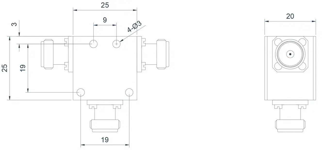
Product Overview
The following products are case examples of UHF-band High Power Coaxial Circulators. Product dimensions and port configurations can be customized based on high-power requirements and high reflected power.
| Model | Frequency(GHz) | BW Max | Insertion loss(dB) Max | Isolation(dB)Min | VSWR Max | Connector | operating temperature(℃) | PK/CW/RP(Watt) | Direction |
|---|---|---|---|---|---|---|---|---|---|
| HCCTA04T10G⬇ | 0.4~1.0 | 10% | 0.4 | 20 | 1.2 | N-K | -55~+85℃ | 2000/200 | Clockwise |
| HCCTB04T10G⬇ | 0.4~1.0 | 10% | 0.4 | 20 | 1.2 | N-K | -55~+85℃ | 2000/200 | Counter Clockwise |
0.8~2.5GHz High Power Coaxial Circulator
Product Overview
The following products are case examples of UHF to S band High Power Coaxial Circulators.Product dimensions and port configurations can be customized based on high-power requirements and high reflected power.
Model
Frequency(GHz)
BW Max
Insertion loss(dB) Max
Isolation(dB)Min
VSWR Max
Connector
operating temperature(℃)
PK/CW/RP(Watt)
Direction
HCCTA08T25G⬇
0.8~2.5
10%
0.4
20
1.2
N-K
-55~+85℃
1500/150
Clockwise
HCCTB08T25G⬇
0.8~2.5
10%
0.4
20
1.2
N-K
-55~+85℃
1500/150
Counter Clockwise
2.0~4.0GHz High Power Coaxial Circulator
Product Overview
The following products are S-band broadband high-power coaxial circulators, designed using high-power materials and improved heat dissipation solutions.
Model
Frequency(GHz)
BW Max
Insertion loss(dB) Max
Isolation(dB)Min
VSWR Max
Connector
operating temperature(℃)
PK/CW/RP(Watt)
Direction
HCCTA20T40G⬇
2.0~4.0
FULL
0.8
15.0
1.5
N-K
-40~+70
-/500
Clockwise
HCCTB20T40G⬇
2.0~4.0
FULL
0.8
15.0
1.5
N-K
-40~+70
-/500
Counter Clockwise
About HzBeat
HzBeat is a leading RF component manufacturer specializing in RF circulators and isolators, as a global supplier of RF circulators and isolators (20MHz–200GHz), we providing microstrip, drop-in, coaxial, and waveguide solutions for communication systems, radar, satellite, and medical imaging.
For detailed technical documentation, sample requests, or customization needs, please do not hesitate to contact us. — we respond within 24 hours to ensure you get precise solutions for your design.
Customization & Selection Guide
- Operating Band:Ensure it covers all frequencies required by your system.
- Power Handling Capacity:Select based on your system's transmit power (average and peak), allowing a certain margin.
- Performance Requirements:Define specific requirements for Insertion Loss, Isolation, and VSWR/Return Loss.
- Environmental Conditions:Consider operating temperature range, vibration, humidity, etc.
- Cost & Delivery:Balance cost and project timeline while meeting performance requirements.
Why Choose Our Product
- Profound Technical Expertise:We have over 18 years of R&D experience in ferrite materials and microwave magnetics.
- Fully Automated Production Lines:Ensure consistent excellence and reliability in every unit.
- Professional Application Support:Our engineering team provides timely technical selection, customization, and failure analysis services.
- Competitive Pricing & Lead Times:Economies of scale from mass production enable us to respond quickly to your orders.
Related Products
Questions? Feel Free to Reach Out Via Message.
Tell us frequency band, target IL/Isolation/VSWR, power level and timeline — we’ll match the best topology and deliver S-parameters.We will contact you within 24 hours.
Product Overview
The following products are case examples of UHF to S band High Power Coaxial Circulators.Product dimensions and port configurations can be customized based on high-power requirements and high reflected power.
| Model | Frequency(GHz) | BW Max | Insertion loss(dB) Max | Isolation(dB)Min | VSWR Max | Connector | operating temperature(℃) | PK/CW/RP(Watt) | Direction |
|---|---|---|---|---|---|---|---|---|---|
| HCCTA08T25G⬇ | 0.8~2.5 | 10% | 0.4 | 20 | 1.2 | N-K | -55~+85℃ | 1500/150 | Clockwise |
| HCCTB08T25G⬇ | 0.8~2.5 | 10% | 0.4 | 20 | 1.2 | N-K | -55~+85℃ | 1500/150 | Counter Clockwise |
2.0~4.0GHz High Power Coaxial Circulator
Product Overview
The following products are S-band broadband high-power coaxial circulators, designed using high-power materials and improved heat dissipation solutions.
Model
Frequency(GHz)
BW Max
Insertion loss(dB) Max
Isolation(dB)Min
VSWR Max
Connector
operating temperature(℃)
PK/CW/RP(Watt)
Direction
HCCTA20T40G⬇
2.0~4.0
FULL
0.8
15.0
1.5
N-K
-40~+70
-/500
Clockwise
HCCTB20T40G⬇
2.0~4.0
FULL
0.8
15.0
1.5
N-K
-40~+70
-/500
Counter Clockwise
About HzBeat
HzBeat is a leading RF component manufacturer specializing in RF circulators and isolators, as a global supplier of RF circulators and isolators (20MHz–200GHz), we providing microstrip, drop-in, coaxial, and waveguide solutions for communication systems, radar, satellite, and medical imaging.
For detailed technical documentation, sample requests, or customization needs, please do not hesitate to contact us. — we respond within 24 hours to ensure you get precise solutions for your design.
Customization & Selection Guide
- Operating Band:Ensure it covers all frequencies required by your system.
- Power Handling Capacity:Select based on your system's transmit power (average and peak), allowing a certain margin.
- Performance Requirements:Define specific requirements for Insertion Loss, Isolation, and VSWR/Return Loss.
- Environmental Conditions:Consider operating temperature range, vibration, humidity, etc.
- Cost & Delivery:Balance cost and project timeline while meeting performance requirements.
Why Choose Our Product
- Profound Technical Expertise:We have over 18 years of R&D experience in ferrite materials and microwave magnetics.
- Fully Automated Production Lines:Ensure consistent excellence and reliability in every unit.
- Professional Application Support:Our engineering team provides timely technical selection, customization, and failure analysis services.
- Competitive Pricing & Lead Times:Economies of scale from mass production enable us to respond quickly to your orders.
Related Products
Questions? Feel Free to Reach Out Via Message.
Tell us frequency band, target IL/Isolation/VSWR, power level and timeline — we’ll match the best topology and deliver S-parameters.We will contact you within 24 hours.
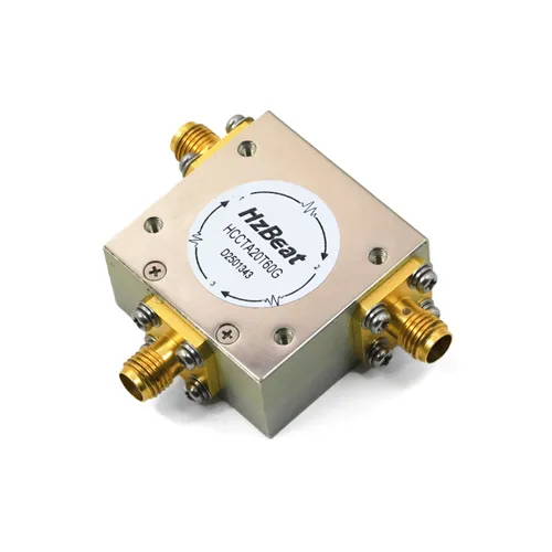
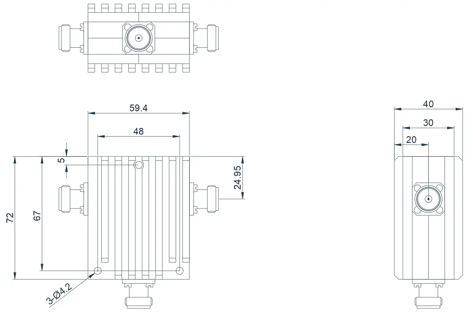
Product Overview
The following products are S-band broadband high-power coaxial circulators, designed using high-power materials and improved heat dissipation solutions.
| Model | Frequency(GHz) | BW Max | Insertion loss(dB) Max | Isolation(dB)Min | VSWR Max | Connector | operating temperature(℃) | PK/CW/RP(Watt) | Direction |
|---|---|---|---|---|---|---|---|---|---|
| HCCTA20T40G⬇ | 2.0~4.0 | FULL | 0.8 | 15.0 | 1.5 | N-K | -40~+70 | -/500 | Clockwise |
| HCCTB20T40G⬇ | 2.0~4.0 | FULL | 0.8 | 15.0 | 1.5 | N-K | -40~+70 | -/500 | Counter Clockwise |
About HzBeat
HzBeat is a leading RF component manufacturer specializing in RF circulators and isolators, as a global supplier of RF circulators and isolators (20MHz–200GHz), we providing microstrip, drop-in, coaxial, and waveguide solutions for communication systems, radar, satellite, and medical imaging.
For detailed technical documentation, sample requests, or customization needs, please do not hesitate to contact us. — we respond within 24 hours to ensure you get precise solutions for your design.
Customization & Selection Guide
- Operating Band:Ensure it covers all frequencies required by your system.
- Power Handling Capacity:Select based on your system's transmit power (average and peak), allowing a certain margin.
- Performance Requirements:Define specific requirements for Insertion Loss, Isolation, and VSWR/Return Loss.
- Environmental Conditions:Consider operating temperature range, vibration, humidity, etc.
- Cost & Delivery:Balance cost and project timeline while meeting performance requirements.
Why Choose Our Product
- Profound Technical Expertise:We have over 18 years of R&D experience in ferrite materials and microwave magnetics.
- Fully Automated Production Lines:Ensure consistent excellence and reliability in every unit.
- Professional Application Support:Our engineering team provides timely technical selection, customization, and failure analysis services.
- Competitive Pricing & Lead Times:Economies of scale from mass production enable us to respond quickly to your orders.