High-Power Circulator & Isolator Solutions
Updated on:
Keywords: RF circulator, isolator, high-power circulator, high-power isolator, ferrite components, waveguide circulator, coaxial isolator, thermal design, non-reciprocal devices, radar, SATCOM, 5G, 6G
Introduction
At kilowatt-class peak or high average power, the RF circulator and isolator shift from optional accessories to essential safeguards against mismatch, protecting HPAs, stabilizing filters, and preserving EIRP under environmental drift and agile frequency plans.
High-Power Definition & Drivers
- Thermal physics: Even 0.3–0.4 dB IL becomes significant heat at scale; ferrite volume and conduction set rating in a RF circulator.
- Field limits: Avoid local E-field peaks, multipaction (space/vacuum), and demagnetization in an isolator.
- System duty cycle: Pulse width/duty, crest factor, and mismatch statistics determine real margin.
Tips:
Quantify average and peak simultaneously; size junction and heatsinking for both steady ΔT and transient margins.
Ferrite Materials & Magnetic Design
Non-reciprocity stems from ferrimagnetic resonance under DC bias. YIG and iron-garnet families dominate due to low linewidth (ΔH), high 4πMs, and favorable temperature coefficients for microwave RF circulator / isolator assemblies.
- ΔH (linewidth): Lower ΔH means lower IL and tighter control; cost and thermal stability trade-offs apply.
- 4πMs & bias: Sets operating window; keep bias margin across –40 °C to +85 °C (or mission range).
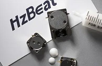
- Demag factors: Puck aspect ratio and junction shapes tune internal fields; rounded edges reduce hotspots.
- Magnet topology: Permanent magnets with shims or compensated alloys stabilize ISO/IL vs. temperature.
Packages for Power: Waveguide / Coaxial / Drop-in
| Package | Bands | Power Envelope | Notes |
|---|---|---|---|
| Waveguide circulator/isolator | L/X/Ku/Ka | Highest peak & CW | Lowest IL; flange standards; favored for radar/SATCOM HPAs |
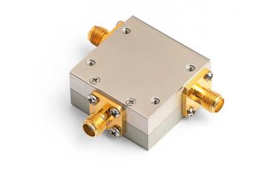
| Coaxial RF isolator | VHF–Ku | High average | Connector limits; compact; careful thermal path |
| Drop-in/microstrip RF circulator | UHF–X | Moderate | PCB stackup and ground pressure critical; add heatsink |
Tips:
For kW-class pulsed radar choose waveguide; for BUC chains balance coaxial convenience vs. thermal headroom.
Thermal Management & Power Budgeting
With IL near 0.4 dB, roughly 9% of forward power is converted to heat. In a 500 W average chain, that means ~45 W inside the isolator or RF circulator. Heatsinking, interface pressure >0.6 MPa, high-k TIM, and airflow or cold-plate design together determine ΔT and demagnetization margin.
- Use lapped interfaces; limit TIM thickness and avoid pump-out at vibration.
- Add copper spreaders or vapor chambers under junctions to cap hotspots.
- Instrument baseplates with thermistors; derate for altitude and ambient spread.
Application Patterns
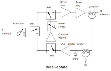
- Radar/EW: Waveguide isolator stages protect TWT/SSPA front-ends during agile tuning.
- SATCOM Gateways: Low-IL RF isolator improves return loss and spectral cleanliness across BUC chains.
- 5G/6G & Labs: Coaxial RF circulator modules route power to combiners, couplers, and loads.
Integration Notes: Matching, PIM, EMC
- Short, clean transitions; correct torque on flanges and connectors.
- PIM targets –150 dBc or better for dense carriers; avoid nickel in current paths.
- Magnet keep-outs; shield sensitive sensors; enforce tool control near magnets.
Reliability & Qualification
| Test | Purpose | Typical Criterion |
|---|---|---|
| Power-on IL drift | Capture ferrite loss vs. ΔT | < 0.1 dB change at rated average power |
| VSWR survival | Mismatch endurance | 2:1–3:1 for ≥10 min without damage |
| Thermal shock & vibe | Field durability | MIL-STD-810/202 pass; no demagnetization |
| Humidity & salt fog | Corrosion resistance | No IL drift beyond spec; cosmetic only |
Selection Checklist
- Band & fractional BW; ISO ≥ 20–30 dB; IL ≤ 0.3–0.6 dB for efficiency.
- Avg/peak power, duty, pulse width; ambient/baseplate temps; allowed ΔT.
- Interfaces: waveguide flange, coax connectors, or drop-in footprints; airflow or cold-plate paths.
- Qualification plan: thermal shock, vibe, humidity, altitude; life test at worst-case mismatch.
Future Outlook: 6G · LEO · mmWave
As networks migrate toward dense carriers and higher microwave/mmWave bands, compact waveguide and robust coaxial non-reciprocal blocks are increasingly favored. LEO gateways benefit from low-IL isolator stages that stabilize BUCs under rapid thermal swings, while 6G test beds rely on compact RF circulator modules to execute safe OTA power sweeps.
Conclusion
Thoughtful execution of ferrite physics, bias, packaging, thermal management, and qualification turns non-reciprocal components into reliable guardians of high-power chains. Well-chosen RF circulator and isolator modules maintain efficiency and uptime under real-world mismatch.
FAQ
How is a RF circulator different from an isolator?
A circulator routes power among three ports (1→2→3→1). An isolator is a two-port form with the third port internally terminated to absorb reflections.
Why choose waveguide for high power?
Waveguide offers lower loss, larger apertures, and superior peak/CW handling compared with most coaxial/PCB formats.
What insertion loss is “good” at high power?
For kilowatt-class systems, strive for ≤0.3–0.6 dB over the band to limit thermal rise and preserve efficiency.
Can different packages be mixed?
Yes—coaxial and waveguide often coexist in BUC chains; verify transitions, PIM, and RL after assembly.
Relateds

About the Author

HzBeat Editorial Content Team
Sara is a Brand Specialist at Hzbeat, focusing on RF & microwave industry communications. She transforms complex technologies into accessible insights, helping global readers understand the value of circulators, isolators, and other key components.