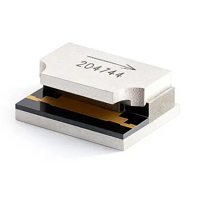
Home/ Microstrip Isolator/ Typical Microstrip Isolator
Typical Microstrip Isolator
S Band, C Band, X Band, Ku Band, K Band, Ka Band (2GHz-40GHz)
- The primary advantage of microstrip Isolators is their compact size, although they have a lower power handling capacity compared to drop-in coaxial waveguide Isolator.
- Customization of frequency bands, dimensions and ports is available according to your requirements.
Key Features & Advantages
- High Performance Isolation & Low Insertion Loss: Delivers >20 dB isolation to suppress reverse signals and maintain source stability, while keeping forward-path insertion loss below 0.5 dB to minimize signal loss.
- Compact & Lightweight Design: Based on a planar microstrip circuit structure, removing bulky metal cavities found in traditional waveguide isolators. This achieves a smaller footprint and lighter weight, well suited for modern electronic miniaturization and integration needs.
- High Power Capacity & Excellent Stability: Uses high-quality ferrite materials and advanced thermal management to support high average and peak power. Delivers stable performance across a wide temperature range, ensuring excellent thermal stability and long-term reliability.
- Broadband Operation: Covers frequency bands from hundreds of MHz to tens of GHz, supporting mainstream wireless, satellite, and radar applications across diverse requirements.
Typical Applications
- Power Amplifier Protection: Placed after the power amplifier, it prevents reflected power caused by antenna impedance mismatch from damaging expensive amplifier transistors.
- Frequency Source Stabilization: Provides a stable load for oscillators (e.g., VCOs, DROs), enhancing frequency stability and phase noise performance.
- Communication Systems: Used for channel isolation and signal quality improvement in base stations, microwave relays, and satellite communication systems.
- Radar Systems: Protects Low-Noise Amplifiers in Transmit/Receive modules, enhancing system dynamic range and reliability.
- Test & Measurement: Used in test setups to protect sensitive instruments such as signal sources and Vector Network Analyzers.
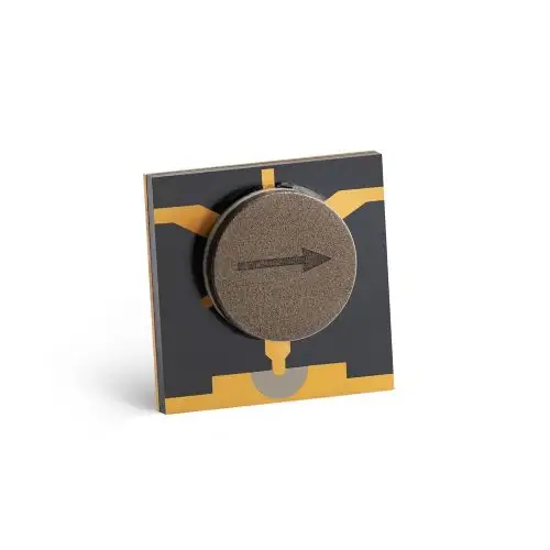
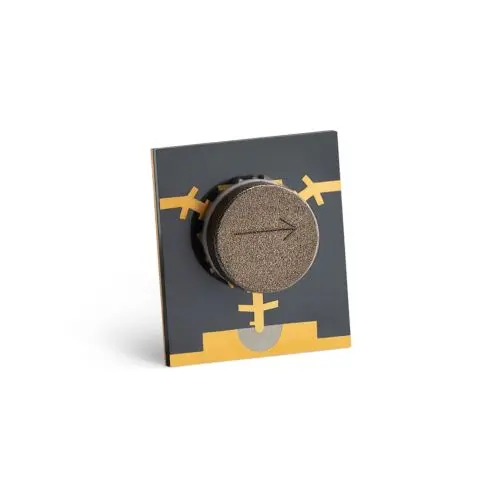
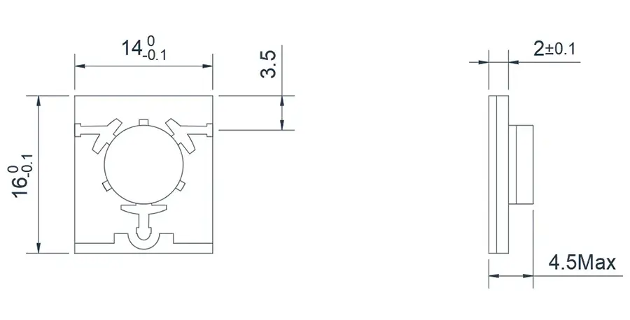
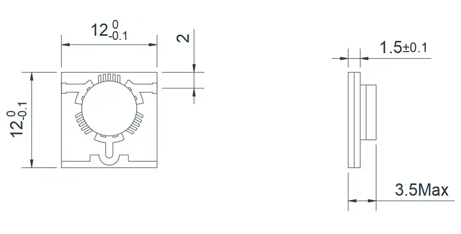
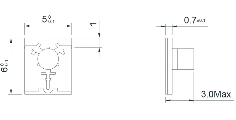
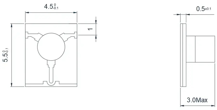
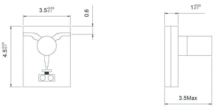
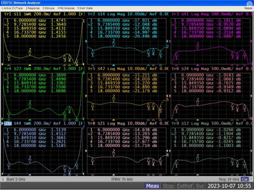
Electrical Performance Table and Product Appearance
2.7~4.0GHz Typical Microstrip 'T' junction Isolator
Model
Frequency(GHz)
BW Max
Insertion loss(dB) Max
Isolation(dB)Min
VSWR Max
operating temperature(℃ )
PK/CW/RP(Watt)
Direction
HMITA27T35G⬇
2.7~3.5
FULL
0.6
20
1.3
-55~+85℃
20/10/5
Clockwise
HMITB27T35G⬇
2.7~3.5
FULL
0.6
20
1.3
-55~+85℃
20/10/5
Counter Clockwise
HMITA30T40G⬇
3.0~4.0
FULL
0.5
18
1.3
-55~+85℃
20/10/5
Clockwise
HMITB30T40G⬇
3.0~4.0
FULL
0.5
18
1.3
-55~+85℃
20/10/5
Counter Clockwise
HMITA35T55G⬇
3.5~5.5
FULL
0.6
16
1.3
-55~+85℃
20/10/5
Clockwise
HMITB35T55G⬇
3.5~5.5
FULL
0.6
16
1.3
-55~+85℃
20/10/5
Counter Clockwise
3.4~5.5GHz Typical Microstrip 'T' junction Isolator
Model
Frequency(GHz)
BW Max
Insertion loss(dB) Max
Isolation(dB)Min
VSWR Max
operating temperature(℃ )
PK/CW/RP(Watt)
Direction
HMITA34T45G⬇
3.4~4.5
FULL
0.6
18
1.3
-55~+85℃
20/10/5
Clockwise
HMITB34T45G⬇
3.4~4.5
FULL
0.6
18
1.3
-55~+85℃
20/10/5
Counter Clockwise
HMITA37T39G⬇
3.7~3.9
FULL
0.5
20
1.25
-55~+85℃
20/10/5
Clockwise
HMITB37T39G⬇
3.7~3.9
FULL
0.5
20
1.25
-55~+85℃
20/10/5
Counter Clockwise
HMITA40T50G⬇
4.0~5.0
FULL
0.5
20
1.25
-55~+85℃
20/10/5
Clockwise
HMITB40T50G⬇
4.0~5.0
FULL
0.5
20
1.25
-55~+85℃
20/10/5
Counter Clockwise
HMITA45T55G⬇
4.5~5.5
FULL
0.5
20
1.25
-55~+85℃
20/10/5
Clockwise
HMITB45T55G⬇
4.5~5.5
FULL
0.5
20
1.25
-55~+85℃
20/10/5
Counter Clockwise
5.0~8.0GHz Typical Microstrip 'T' junction Isolator
Model
Frequency(GHz)
BW Max
Insertion loss(dB) Max
Isolation(dB)Min
VSWR Max
operating temperature(℃ )
PK/CW/RP(Watt)
Direction
HMITA50T60G⬇
5.0~6.0
FULL
0.5
20
1.25
-55~+85℃
20/10/5
Clockwise
HMITB50T60G⬇
5.0~6.0
FULL
0.5
20
1.25
-55~+85℃
20/10/5
Counter Clockwise
HMITA55T65G⬇
5.5~6.5
FULL
0.5
20
1.25
-55~+85℃
20/10/5
Clockwise
HMITB55T65G⬇
5.5~6.5
FULL
0.5
20
1.25
-55~+85℃
20/10/5
Counter Clockwise
HMITA65T75G⬇
6.5~7.5
FULL
0.5
20
1.25
-55~+85℃
20/10/5
Clockwise
HMITB65T75G⬇
6.5~7.5
FULL
0.5
20
1.25
-55~+85℃
20/10/5
Counter Clockwise
HMITA50T80G⬇
5.0~8.0
FULL
0.6
18
1.3
-55~+85℃
20/10/5
Clockwise
HMITB50T80G⬇
5.0~8.0
FULL
0.6
18
1.3
-55~+85℃
20/10/5
Counter Clockwise
HMITA60T80G⬇
6.0~8.0
FULL
0.5
20
1.25
-55~+85℃
20/10/5
Clockwise
HMITB60T80G⬇
6.0~8.0
FULL
0.5
20
1.25
-55~+85℃
20/10/5
Counter Clockwise
7.0~9.5GHz Typical Microstrip 'T' junction Isolator
Model
Frequency(GHz)
BW Max
Insertion loss(dB) Max
Isolation(dB)Min
VSWR Max
operating temperature(℃ )
PK/CW/RP(Watt)
Direction
HMITA70T95G⬇
7.0~9.5
FULL
0.6
17
1.35
-55~+85℃
20/10/3
Clockwise
HMITB70T95G⬇
7.0~9.5
FULL
0.6
17
1.35
-55~+85℃
20/10/3
Counter Clockwise
HMITA75T95G⬇
7.5~9.5
FULL
0.5
18
1.3
-55~+85℃
20/10/3
Clockwise
HMITB75T95G⬇
7.5~9.5
FULL
0.5
18
1.3
-55~+85℃
20/10/3
Counter Clockwise
8.0~18.0GHz Typical Microstrip 'T' junction Isolator
Model
Frequency(GHz)
BW Max
Insertion loss(dB) Max
Isolation(dB)Min
VSWR Max
operating temperature(℃ )
PK/CW/RP(Watt)
Direction
HMITA80T100G⬇
8.0~10.0
FULL
0.5
20
1.25
-55~+85℃
20/10/3
Clockwise
HMITB80T100G⬇
8.0~10.0
FULL
0.5
20
1.25
-55~+85℃
20/10/3
Counter Clockwise
HMITA85T105G⬇
8.5~10.5
FULL
0.5
20
1.25
-55~+85℃
20/10/3
Clockwise
HMITB85T105G⬇
8.5~10.5
FULL
0.5
20
1.25
-55~+85℃
20/10/3
Counter Clockwise
HMITA80T120G⬇
8.0~12.0
FULL
0.6
18
1.35
-55~+85℃
20/10/3
Clockwise
HMITB80T120G⬇
8.0~12.0
FULL
0.6
18
1.35
-55~+85℃
20/10/3
Counter Clockwise
HMITA90T110G⬇
9.0~11.0
FULL
0.5
20
1.25
-55~+85℃
20/10/3
Clockwise
HMITB90T110G⬇
9.0~11.0
FULL
0.5
20
1.25
-55~+85℃
20/10/3
Counter Clockwise
HMITA100T120G⬇
10.0~12.0
FULL
0.5
20
1.25
-55~+85℃
20/10/3
Clockwise
HMITB100T120G⬇
10.0~12.0
FULL
0.5
20
1.25
-55~+85℃
20/10/3
Counter Clockwise
HMITA110T130G⬇
11.0~13.0
FULL
0.5
20
1.25
-55~+85℃
20/10/3
Clockwise
HMITB110T130G⬇
11.0~13.0
FULL
0.5
20
1.25
-55~+85℃
20/10/3
Counter Clockwise
HMITA120T150G⬇
12.0~15.0
FULL
0.5
18
1.3
-55~+85℃
20/10/3
Clockwise
HMITB120T150G⬇
12.0~15.0
FULL
0.5
18
1.3
-55~+85℃
20/10/3
Counter Clockwise
HMITA120T180G⬇
12.0~18.0
FULL
0.7
16
1.4
-55~+85℃
20/10/3
Clockwise
HMITB120T180G⬇
12.0~18.0
FULL
0.7
16
1.4
-55~+85℃
20/10/3
Counter Clockwise
14.0~20.0GHz Typical Microstrip 'T' junction Isolator
Model
Frequency(GHz)
BW Max
Insertion loss(dB) Max
Isolation(dB)Min
VSWR Max
operating temperature(℃ )
PK/CW/RP(Watt)
Direction
HMITA140T180G⬇
14.0~18.0
FULL
0.5
20
1.25
-55~+85℃
20/10/2
Clockwise
HMITB140T180G⬇
14.0~18.0
FULL
0.5
20
1.25
-55~+85℃
20/10/2
Counter Clockwise
HMITA150T200G⬇
15.0~20.0
FULL
0.6
18
1.3
-55~+85℃
20/10/2
Clockwise
HMITB150T200G⬇
15.0~20.0
FULL
0.6
18
1.3
-55~+85℃
20/10/2
Counter Clockwise
18.0~28.0GHz Typical Microstrip 'T' junction Isolator
Model
Frequency(GHz)
BW Max
Insertion loss(dB) Max
Isolation(dB)Min
VSWR Max
operating temperature(℃ )
PK/CW/RP(Watt)
Direction
HMITA180T220G⬇
18.0~22.0
FULL
0.5
20
1.25
-55~+85℃
15/5/2
Clockwise
HMITB180T220G⬇
18.0~22.0
FULL
0.5
20
1.25
-55~+85℃
15/5/2
Counter Clockwise
HMITA180T240G⬇
18.0~24.0
FULL
0.6
18
1.3
-55~+85℃
15/5/2
Clockwise
HMITB180T240G⬇
18.0~24.0
FULL
0.6
18
1.3
-55~+85℃
15/5/2
Counter Clockwise
HMITA240T280G⬇
24.0~28.0
FULL
0.7
18
1.3
-55~+85℃
5/2/1
Clockwise
HMITB240T280G⬇
24.0~28.0
FULL
0.7
18
1.3
-55~+85℃
5/2/1
Counter Clockwise
28.0~40.0GHz Typical Microstrip 'T' junction Isolator
Model
Frequency(GHz)
BW Max
Insertion loss(dB) Max
Isolation(dB)Min
VSWR Max
operating temperature(℃ )
PK/CW/RP(Watt)
Direction
HMITA280T320G⬇
28.0~32.0
FULL
0.7
18
1.35
-55~+85℃
5/2/1
Clockwise
HMITB280T320G⬇
28.0~32.0
FULL
0.7
18
1.35
-55~+85℃
5/2/1
Counter Clockwise
HMITA330T370G⬇
33.0~37.0
FULL
0.7
18
1.35
-55~+85℃
5/2/1
Clockwise
HMITB330T370G⬇
33.0~37.0
FULL
0.7
18
1.35
-55~+85℃
5/2/1
Counter Clockwise
HMITA320T380G⬇
32.0~38.0
FULL
0.8
17
1.4
-55~+85℃
5/2/1
Clockwise
HMITB320T380G⬇
32.0~38.0
FULL
0.8
17
1.4
-55~+85℃
5/2/1
Counter Clockwise
HMITA320T400G⬇
32.0~40.0
FULL
1.0
14
1.4
-55~+85℃
5/2/1
Clockwise
HMITB320T400G⬇
32.0~40.0
FULL
1.0
14
1.4
-55~+85℃
5/2/1
Counter Clockwise
HMITA380T400G⬇
38.0~40.0
FULL
0.7
20
1.35
-55~+85℃
5/2/1
Clockwise
HMITB380T400G⬇
38.0~40.0
FULL
0.7
20
1.35
-55~+85℃
5/2/1
Counter Clockwise
HMITA27T35G 2.7~4.0GHz
HMITA27T35G 2.7~4.0GHz
About HzBeat
HzBeat is a leading RF component manufacturer specializing in RF circulators and isolators, as a global supplier of RF circulators and isolators (20MHz–200GHz), we providing microstrip, drop-in, coaxial, and waveguide solutions for communication systems, radar, satellite, and medical imaging.
For detailed technical documentation, sample requests, or customization needs, please do not hesitate to contact us. — we respond within 24 hours to ensure you get precise solutions for your design.
Customization & Selection Guide
- Operating Band:Ensure it covers all frequencies required by your system.
- Power Handling Capacity:Select based on your system's transmit power (average and peak), allowing a certain margin.
- Performance Requirements:Define specific requirements for Insertion Loss, Isolation, and VSWR/Return Loss.
- Environmental Conditions:Consider operating temperature range, vibration, humidity, etc.
- Cost & Delivery:Balance cost and project timeline while meeting performance requirements.
Why Choose Our Product
- Profound Technical Expertise:We have over 18 years of R&D experience in ferrite materials and microwave magnetics.
- Fully Automated Production Lines:Ensure consistent excellence and reliability in every unit.
- Professional Application Support:Our engineering team provides timely technical selection, customization, and failure analysis services.
- Competitive Pricing & Lead Times:Economies of scale from mass production enable us to respond quickly to your orders.
Related Products
Questions? Feel Free to Reach Out Via Message.
Tell us frequency band, target IL/Isolation/VSWR, power level and timeline — we’ll match the best topology and deliver S-parameters.We will contact you within 24 hours.
| Model | Frequency(GHz) | BW Max | Insertion loss(dB) Max | Isolation(dB)Min | VSWR Max | operating temperature(℃ ) | PK/CW/RP(Watt) | Direction |
|---|---|---|---|---|---|---|---|---|
| HMITA27T35G⬇ | 2.7~3.5 | FULL | 0.6 | 20 | 1.3 | -55~+85℃ | 20/10/5 | Clockwise |
| HMITB27T35G⬇ | 2.7~3.5 | FULL | 0.6 | 20 | 1.3 | -55~+85℃ | 20/10/5 | Counter Clockwise |
| HMITA30T40G⬇ | 3.0~4.0 | FULL | 0.5 | 18 | 1.3 | -55~+85℃ | 20/10/5 | Clockwise |
| HMITB30T40G⬇ | 3.0~4.0 | FULL | 0.5 | 18 | 1.3 | -55~+85℃ | 20/10/5 | Counter Clockwise |
| HMITA35T55G⬇ | 3.5~5.5 | FULL | 0.6 | 16 | 1.3 | -55~+85℃ | 20/10/5 | Clockwise |
| HMITB35T55G⬇ | 3.5~5.5 | FULL | 0.6 | 16 | 1.3 | -55~+85℃ | 20/10/5 | Counter Clockwise |
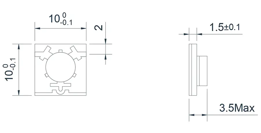
3.4~5.5GHz Typical Microstrip 'T' junction Isolator
Model
Frequency(GHz)
BW Max
Insertion loss(dB) Max
Isolation(dB)Min
VSWR Max
operating temperature(℃ )
PK/CW/RP(Watt)
Direction
HMITA34T45G⬇
3.4~4.5
FULL
0.6
18
1.3
-55~+85℃
20/10/5
Clockwise
HMITB34T45G⬇
3.4~4.5
FULL
0.6
18
1.3
-55~+85℃
20/10/5
Counter Clockwise
HMITA37T39G⬇
3.7~3.9
FULL
0.5
20
1.25
-55~+85℃
20/10/5
Clockwise
HMITB37T39G⬇
3.7~3.9
FULL
0.5
20
1.25
-55~+85℃
20/10/5
Counter Clockwise
HMITA40T50G⬇
4.0~5.0
FULL
0.5
20
1.25
-55~+85℃
20/10/5
Clockwise
HMITB40T50G⬇
4.0~5.0
FULL
0.5
20
1.25
-55~+85℃
20/10/5
Counter Clockwise
HMITA45T55G⬇
4.5~5.5
FULL
0.5
20
1.25
-55~+85℃
20/10/5
Clockwise
HMITB45T55G⬇
4.5~5.5
FULL
0.5
20
1.25
-55~+85℃
20/10/5
Counter Clockwise
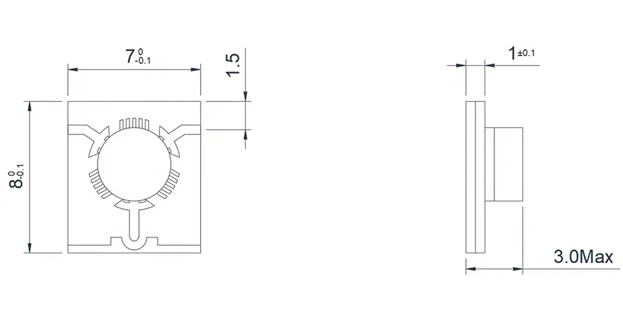
5.0~8.0GHz Typical Microstrip 'T' junction Isolator
Model
Frequency(GHz)
BW Max
Insertion loss(dB) Max
Isolation(dB)Min
VSWR Max
operating temperature(℃ )
PK/CW/RP(Watt)
Direction
HMITA50T60G⬇
5.0~6.0
FULL
0.5
20
1.25
-55~+85℃
20/10/5
Clockwise
HMITB50T60G⬇
5.0~6.0
FULL
0.5
20
1.25
-55~+85℃
20/10/5
Counter Clockwise
HMITA55T65G⬇
5.5~6.5
FULL
0.5
20
1.25
-55~+85℃
20/10/5
Clockwise
HMITB55T65G⬇
5.5~6.5
FULL
0.5
20
1.25
-55~+85℃
20/10/5
Counter Clockwise
HMITA65T75G⬇
6.5~7.5
FULL
0.5
20
1.25
-55~+85℃
20/10/5
Clockwise
HMITB65T75G⬇
6.5~7.5
FULL
0.5
20
1.25
-55~+85℃
20/10/5
Counter Clockwise
HMITA50T80G⬇
5.0~8.0
FULL
0.6
18
1.3
-55~+85℃
20/10/5
Clockwise
HMITB50T80G⬇
5.0~8.0
FULL
0.6
18
1.3
-55~+85℃
20/10/5
Counter Clockwise
HMITA60T80G⬇
6.0~8.0
FULL
0.5
20
1.25
-55~+85℃
20/10/5
Clockwise
HMITB60T80G⬇
6.0~8.0
FULL
0.5
20
1.25
-55~+85℃
20/10/5
Counter Clockwise
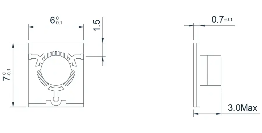
7.0~9.5GHz Typical Microstrip 'T' junction Isolator
Model
Frequency(GHz)
BW Max
Insertion loss(dB) Max
Isolation(dB)Min
VSWR Max
operating temperature(℃ )
PK/CW/RP(Watt)
Direction
HMITA70T95G⬇
7.0~9.5
FULL
0.6
17
1.35
-55~+85℃
20/10/3
Clockwise
HMITB70T95G⬇
7.0~9.5
FULL
0.6
17
1.35
-55~+85℃
20/10/3
Counter Clockwise
HMITA75T95G⬇
7.5~9.5
FULL
0.5
18
1.3
-55~+85℃
20/10/3
Clockwise
HMITB75T95G⬇
7.5~9.5
FULL
0.5
18
1.3
-55~+85℃
20/10/3
Counter Clockwise
8.0~18.0GHz Typical Microstrip 'T' junction Isolator
Model
Frequency(GHz)
BW Max
Insertion loss(dB) Max
Isolation(dB)Min
VSWR Max
operating temperature(℃ )
PK/CW/RP(Watt)
Direction
HMITA80T100G⬇
8.0~10.0
FULL
0.5
20
1.25
-55~+85℃
20/10/3
Clockwise
HMITB80T100G⬇
8.0~10.0
FULL
0.5
20
1.25
-55~+85℃
20/10/3
Counter Clockwise
HMITA85T105G⬇
8.5~10.5
FULL
0.5
20
1.25
-55~+85℃
20/10/3
Clockwise
HMITB85T105G⬇
8.5~10.5
FULL
0.5
20
1.25
-55~+85℃
20/10/3
Counter Clockwise
HMITA80T120G⬇
8.0~12.0
FULL
0.6
18
1.35
-55~+85℃
20/10/3
Clockwise
HMITB80T120G⬇
8.0~12.0
FULL
0.6
18
1.35
-55~+85℃
20/10/3
Counter Clockwise
HMITA90T110G⬇
9.0~11.0
FULL
0.5
20
1.25
-55~+85℃
20/10/3
Clockwise
HMITB90T110G⬇
9.0~11.0
FULL
0.5
20
1.25
-55~+85℃
20/10/3
Counter Clockwise
HMITA100T120G⬇
10.0~12.0
FULL
0.5
20
1.25
-55~+85℃
20/10/3
Clockwise
HMITB100T120G⬇
10.0~12.0
FULL
0.5
20
1.25
-55~+85℃
20/10/3
Counter Clockwise
HMITA110T130G⬇
11.0~13.0
FULL
0.5
20
1.25
-55~+85℃
20/10/3
Clockwise
HMITB110T130G⬇
11.0~13.0
FULL
0.5
20
1.25
-55~+85℃
20/10/3
Counter Clockwise
HMITA120T150G⬇
12.0~15.0
FULL
0.5
18
1.3
-55~+85℃
20/10/3
Clockwise
HMITB120T150G⬇
12.0~15.0
FULL
0.5
18
1.3
-55~+85℃
20/10/3
Counter Clockwise
HMITA120T180G⬇
12.0~18.0
FULL
0.7
16
1.4
-55~+85℃
20/10/3
Clockwise
HMITB120T180G⬇
12.0~18.0
FULL
0.7
16
1.4
-55~+85℃
20/10/3
Counter Clockwise
14.0~20.0GHz Typical Microstrip 'T' junction Isolator
Model
Frequency(GHz)
BW Max
Insertion loss(dB) Max
Isolation(dB)Min
VSWR Max
operating temperature(℃ )
PK/CW/RP(Watt)
Direction
HMITA140T180G⬇
14.0~18.0
FULL
0.5
20
1.25
-55~+85℃
20/10/2
Clockwise
HMITB140T180G⬇
14.0~18.0
FULL
0.5
20
1.25
-55~+85℃
20/10/2
Counter Clockwise
HMITA150T200G⬇
15.0~20.0
FULL
0.6
18
1.3
-55~+85℃
20/10/2
Clockwise
HMITB150T200G⬇
15.0~20.0
FULL
0.6
18
1.3
-55~+85℃
20/10/2
Counter Clockwise
18.0~28.0GHz Typical Microstrip 'T' junction Isolator
Model
Frequency(GHz)
BW Max
Insertion loss(dB) Max
Isolation(dB)Min
VSWR Max
operating temperature(℃ )
PK/CW/RP(Watt)
Direction
HMITA180T220G⬇
18.0~22.0
FULL
0.5
20
1.25
-55~+85℃
15/5/2
Clockwise
HMITB180T220G⬇
18.0~22.0
FULL
0.5
20
1.25
-55~+85℃
15/5/2
Counter Clockwise
HMITA180T240G⬇
18.0~24.0
FULL
0.6
18
1.3
-55~+85℃
15/5/2
Clockwise
HMITB180T240G⬇
18.0~24.0
FULL
0.6
18
1.3
-55~+85℃
15/5/2
Counter Clockwise
HMITA240T280G⬇
24.0~28.0
FULL
0.7
18
1.3
-55~+85℃
5/2/1
Clockwise
HMITB240T280G⬇
24.0~28.0
FULL
0.7
18
1.3
-55~+85℃
5/2/1
Counter Clockwise
28.0~40.0GHz Typical Microstrip 'T' junction Isolator
Model
Frequency(GHz)
BW Max
Insertion loss(dB) Max
Isolation(dB)Min
VSWR Max
operating temperature(℃ )
PK/CW/RP(Watt)
Direction
HMITA280T320G⬇
28.0~32.0
FULL
0.7
18
1.35
-55~+85℃
5/2/1
Clockwise
HMITB280T320G⬇
28.0~32.0
FULL
0.7
18
1.35
-55~+85℃
5/2/1
Counter Clockwise
HMITA330T370G⬇
33.0~37.0
FULL
0.7
18
1.35
-55~+85℃
5/2/1
Clockwise
HMITB330T370G⬇
33.0~37.0
FULL
0.7
18
1.35
-55~+85℃
5/2/1
Counter Clockwise
HMITA320T380G⬇
32.0~38.0
FULL
0.8
17
1.4
-55~+85℃
5/2/1
Clockwise
HMITB320T380G⬇
32.0~38.0
FULL
0.8
17
1.4
-55~+85℃
5/2/1
Counter Clockwise
HMITA320T400G⬇
32.0~40.0
FULL
1.0
14
1.4
-55~+85℃
5/2/1
Clockwise
HMITB320T400G⬇
32.0~40.0
FULL
1.0
14
1.4
-55~+85℃
5/2/1
Counter Clockwise
HMITA380T400G⬇
38.0~40.0
FULL
0.7
20
1.35
-55~+85℃
5/2/1
Clockwise
HMITB380T400G⬇
38.0~40.0
FULL
0.7
20
1.35
-55~+85℃
5/2/1
Counter Clockwise
HMITA27T35G 2.7~4.0GHz
HMITA27T35G 2.7~4.0GHz
About HzBeat
HzBeat is a leading RF component manufacturer specializing in RF circulators and isolators, as a global supplier of RF circulators and isolators (20MHz–200GHz), we providing microstrip, drop-in, coaxial, and waveguide solutions for communication systems, radar, satellite, and medical imaging.
For detailed technical documentation, sample requests, or customization needs, please do not hesitate to contact us. — we respond within 24 hours to ensure you get precise solutions for your design.
Customization & Selection Guide
- Operating Band:Ensure it covers all frequencies required by your system.
- Power Handling Capacity:Select based on your system's transmit power (average and peak), allowing a certain margin.
- Performance Requirements:Define specific requirements for Insertion Loss, Isolation, and VSWR/Return Loss.
- Environmental Conditions:Consider operating temperature range, vibration, humidity, etc.
- Cost & Delivery:Balance cost and project timeline while meeting performance requirements.
Why Choose Our Product
- Profound Technical Expertise:We have over 18 years of R&D experience in ferrite materials and microwave magnetics.
- Fully Automated Production Lines:Ensure consistent excellence and reliability in every unit.
- Professional Application Support:Our engineering team provides timely technical selection, customization, and failure analysis services.
- Competitive Pricing & Lead Times:Economies of scale from mass production enable us to respond quickly to your orders.
Related Products
Questions? Feel Free to Reach Out Via Message.
Tell us frequency band, target IL/Isolation/VSWR, power level and timeline — we’ll match the best topology and deliver S-parameters.We will contact you within 24 hours.
| Model | Frequency(GHz) | BW Max | Insertion loss(dB) Max | Isolation(dB)Min | VSWR Max | operating temperature(℃ ) | PK/CW/RP(Watt) | Direction |
|---|---|---|---|---|---|---|---|---|
| HMITA34T45G⬇ | 3.4~4.5 | FULL | 0.6 | 18 | 1.3 | -55~+85℃ | 20/10/5 | Clockwise |
| HMITB34T45G⬇ | 3.4~4.5 | FULL | 0.6 | 18 | 1.3 | -55~+85℃ | 20/10/5 | Counter Clockwise |
| HMITA37T39G⬇ | 3.7~3.9 | FULL | 0.5 | 20 | 1.25 | -55~+85℃ | 20/10/5 | Clockwise |
| HMITB37T39G⬇ | 3.7~3.9 | FULL | 0.5 | 20 | 1.25 | -55~+85℃ | 20/10/5 | Counter Clockwise |
| HMITA40T50G⬇ | 4.0~5.0 | FULL | 0.5 | 20 | 1.25 | -55~+85℃ | 20/10/5 | Clockwise |
| HMITB40T50G⬇ | 4.0~5.0 | FULL | 0.5 | 20 | 1.25 | -55~+85℃ | 20/10/5 | Counter Clockwise |
| HMITA45T55G⬇ | 4.5~5.5 | FULL | 0.5 | 20 | 1.25 | -55~+85℃ | 20/10/5 | Clockwise |
| HMITB45T55G⬇ | 4.5~5.5 | FULL | 0.5 | 20 | 1.25 | -55~+85℃ | 20/10/5 | Counter Clockwise |
5.0~8.0GHz Typical Microstrip 'T' junction Isolator
Model
Frequency(GHz)
BW Max
Insertion loss(dB) Max
Isolation(dB)Min
VSWR Max
operating temperature(℃ )
PK/CW/RP(Watt)
Direction
HMITA50T60G⬇
5.0~6.0
FULL
0.5
20
1.25
-55~+85℃
20/10/5
Clockwise
HMITB50T60G⬇
5.0~6.0
FULL
0.5
20
1.25
-55~+85℃
20/10/5
Counter Clockwise
HMITA55T65G⬇
5.5~6.5
FULL
0.5
20
1.25
-55~+85℃
20/10/5
Clockwise
HMITB55T65G⬇
5.5~6.5
FULL
0.5
20
1.25
-55~+85℃
20/10/5
Counter Clockwise
HMITA65T75G⬇
6.5~7.5
FULL
0.5
20
1.25
-55~+85℃
20/10/5
Clockwise
HMITB65T75G⬇
6.5~7.5
FULL
0.5
20
1.25
-55~+85℃
20/10/5
Counter Clockwise
HMITA50T80G⬇
5.0~8.0
FULL
0.6
18
1.3
-55~+85℃
20/10/5
Clockwise
HMITB50T80G⬇
5.0~8.0
FULL
0.6
18
1.3
-55~+85℃
20/10/5
Counter Clockwise
HMITA60T80G⬇
6.0~8.0
FULL
0.5
20
1.25
-55~+85℃
20/10/5
Clockwise
HMITB60T80G⬇
6.0~8.0
FULL
0.5
20
1.25
-55~+85℃
20/10/5
Counter Clockwise
7.0~9.5GHz Typical Microstrip 'T' junction Isolator
Model
Frequency(GHz)
BW Max
Insertion loss(dB) Max
Isolation(dB)Min
VSWR Max
operating temperature(℃ )
PK/CW/RP(Watt)
Direction
HMITA70T95G⬇
7.0~9.5
FULL
0.6
17
1.35
-55~+85℃
20/10/3
Clockwise
HMITB70T95G⬇
7.0~9.5
FULL
0.6
17
1.35
-55~+85℃
20/10/3
Counter Clockwise
HMITA75T95G⬇
7.5~9.5
FULL
0.5
18
1.3
-55~+85℃
20/10/3
Clockwise
HMITB75T95G⬇
7.5~9.5
FULL
0.5
18
1.3
-55~+85℃
20/10/3
Counter Clockwise
8.0~18.0GHz Typical Microstrip 'T' junction Isolator
Model
Frequency(GHz)
BW Max
Insertion loss(dB) Max
Isolation(dB)Min
VSWR Max
operating temperature(℃ )
PK/CW/RP(Watt)
Direction
HMITA80T100G⬇
8.0~10.0
FULL
0.5
20
1.25
-55~+85℃
20/10/3
Clockwise
HMITB80T100G⬇
8.0~10.0
FULL
0.5
20
1.25
-55~+85℃
20/10/3
Counter Clockwise
HMITA85T105G⬇
8.5~10.5
FULL
0.5
20
1.25
-55~+85℃
20/10/3
Clockwise
HMITB85T105G⬇
8.5~10.5
FULL
0.5
20
1.25
-55~+85℃
20/10/3
Counter Clockwise
HMITA80T120G⬇
8.0~12.0
FULL
0.6
18
1.35
-55~+85℃
20/10/3
Clockwise
HMITB80T120G⬇
8.0~12.0
FULL
0.6
18
1.35
-55~+85℃
20/10/3
Counter Clockwise
HMITA90T110G⬇
9.0~11.0
FULL
0.5
20
1.25
-55~+85℃
20/10/3
Clockwise
HMITB90T110G⬇
9.0~11.0
FULL
0.5
20
1.25
-55~+85℃
20/10/3
Counter Clockwise
HMITA100T120G⬇
10.0~12.0
FULL
0.5
20
1.25
-55~+85℃
20/10/3
Clockwise
HMITB100T120G⬇
10.0~12.0
FULL
0.5
20
1.25
-55~+85℃
20/10/3
Counter Clockwise
HMITA110T130G⬇
11.0~13.0
FULL
0.5
20
1.25
-55~+85℃
20/10/3
Clockwise
HMITB110T130G⬇
11.0~13.0
FULL
0.5
20
1.25
-55~+85℃
20/10/3
Counter Clockwise
HMITA120T150G⬇
12.0~15.0
FULL
0.5
18
1.3
-55~+85℃
20/10/3
Clockwise
HMITB120T150G⬇
12.0~15.0
FULL
0.5
18
1.3
-55~+85℃
20/10/3
Counter Clockwise
HMITA120T180G⬇
12.0~18.0
FULL
0.7
16
1.4
-55~+85℃
20/10/3
Clockwise
HMITB120T180G⬇
12.0~18.0
FULL
0.7
16
1.4
-55~+85℃
20/10/3
Counter Clockwise
14.0~20.0GHz Typical Microstrip 'T' junction Isolator
Model
Frequency(GHz)
BW Max
Insertion loss(dB) Max
Isolation(dB)Min
VSWR Max
operating temperature(℃ )
PK/CW/RP(Watt)
Direction
HMITA140T180G⬇
14.0~18.0
FULL
0.5
20
1.25
-55~+85℃
20/10/2
Clockwise
HMITB140T180G⬇
14.0~18.0
FULL
0.5
20
1.25
-55~+85℃
20/10/2
Counter Clockwise
HMITA150T200G⬇
15.0~20.0
FULL
0.6
18
1.3
-55~+85℃
20/10/2
Clockwise
HMITB150T200G⬇
15.0~20.0
FULL
0.6
18
1.3
-55~+85℃
20/10/2
Counter Clockwise
18.0~28.0GHz Typical Microstrip 'T' junction Isolator
Model
Frequency(GHz)
BW Max
Insertion loss(dB) Max
Isolation(dB)Min
VSWR Max
operating temperature(℃ )
PK/CW/RP(Watt)
Direction
HMITA180T220G⬇
18.0~22.0
FULL
0.5
20
1.25
-55~+85℃
15/5/2
Clockwise
HMITB180T220G⬇
18.0~22.0
FULL
0.5
20
1.25
-55~+85℃
15/5/2
Counter Clockwise
HMITA180T240G⬇
18.0~24.0
FULL
0.6
18
1.3
-55~+85℃
15/5/2
Clockwise
HMITB180T240G⬇
18.0~24.0
FULL
0.6
18
1.3
-55~+85℃
15/5/2
Counter Clockwise
HMITA240T280G⬇
24.0~28.0
FULL
0.7
18
1.3
-55~+85℃
5/2/1
Clockwise
HMITB240T280G⬇
24.0~28.0
FULL
0.7
18
1.3
-55~+85℃
5/2/1
Counter Clockwise
28.0~40.0GHz Typical Microstrip 'T' junction Isolator
Model
Frequency(GHz)
BW Max
Insertion loss(dB) Max
Isolation(dB)Min
VSWR Max
operating temperature(℃ )
PK/CW/RP(Watt)
Direction
HMITA280T320G⬇
28.0~32.0
FULL
0.7
18
1.35
-55~+85℃
5/2/1
Clockwise
HMITB280T320G⬇
28.0~32.0
FULL
0.7
18
1.35
-55~+85℃
5/2/1
Counter Clockwise
HMITA330T370G⬇
33.0~37.0
FULL
0.7
18
1.35
-55~+85℃
5/2/1
Clockwise
HMITB330T370G⬇
33.0~37.0
FULL
0.7
18
1.35
-55~+85℃
5/2/1
Counter Clockwise
HMITA320T380G⬇
32.0~38.0
FULL
0.8
17
1.4
-55~+85℃
5/2/1
Clockwise
HMITB320T380G⬇
32.0~38.0
FULL
0.8
17
1.4
-55~+85℃
5/2/1
Counter Clockwise
HMITA320T400G⬇
32.0~40.0
FULL
1.0
14
1.4
-55~+85℃
5/2/1
Clockwise
HMITB320T400G⬇
32.0~40.0
FULL
1.0
14
1.4
-55~+85℃
5/2/1
Counter Clockwise
HMITA380T400G⬇
38.0~40.0
FULL
0.7
20
1.35
-55~+85℃
5/2/1
Clockwise
HMITB380T400G⬇
38.0~40.0
FULL
0.7
20
1.35
-55~+85℃
5/2/1
Counter Clockwise
HMITA27T35G 2.7~4.0GHz
HMITA27T35G 2.7~4.0GHz
About HzBeat
HzBeat is a leading RF component manufacturer specializing in RF circulators and isolators, as a global supplier of RF circulators and isolators (20MHz–200GHz), we providing microstrip, drop-in, coaxial, and waveguide solutions for communication systems, radar, satellite, and medical imaging.
For detailed technical documentation, sample requests, or customization needs, please do not hesitate to contact us. — we respond within 24 hours to ensure you get precise solutions for your design.
Customization & Selection Guide
- Operating Band:Ensure it covers all frequencies required by your system.
- Power Handling Capacity:Select based on your system's transmit power (average and peak), allowing a certain margin.
- Performance Requirements:Define specific requirements for Insertion Loss, Isolation, and VSWR/Return Loss.
- Environmental Conditions:Consider operating temperature range, vibration, humidity, etc.
- Cost & Delivery:Balance cost and project timeline while meeting performance requirements.
Why Choose Our Product
- Profound Technical Expertise:We have over 18 years of R&D experience in ferrite materials and microwave magnetics.
- Fully Automated Production Lines:Ensure consistent excellence and reliability in every unit.
- Professional Application Support:Our engineering team provides timely technical selection, customization, and failure analysis services.
- Competitive Pricing & Lead Times:Economies of scale from mass production enable us to respond quickly to your orders.
Related Products
Questions? Feel Free to Reach Out Via Message.
Tell us frequency band, target IL/Isolation/VSWR, power level and timeline — we’ll match the best topology and deliver S-parameters.We will contact you within 24 hours.
| Model | Frequency(GHz) | BW Max | Insertion loss(dB) Max | Isolation(dB)Min | VSWR Max | operating temperature(℃ ) | PK/CW/RP(Watt) | Direction |
|---|---|---|---|---|---|---|---|---|
| HMITA50T60G⬇ | 5.0~6.0 | FULL | 0.5 | 20 | 1.25 | -55~+85℃ | 20/10/5 | Clockwise |
| HMITB50T60G⬇ | 5.0~6.0 | FULL | 0.5 | 20 | 1.25 | -55~+85℃ | 20/10/5 | Counter Clockwise |
| HMITA55T65G⬇ | 5.5~6.5 | FULL | 0.5 | 20 | 1.25 | -55~+85℃ | 20/10/5 | Clockwise |
| HMITB55T65G⬇ | 5.5~6.5 | FULL | 0.5 | 20 | 1.25 | -55~+85℃ | 20/10/5 | Counter Clockwise |
| HMITA65T75G⬇ | 6.5~7.5 | FULL | 0.5 | 20 | 1.25 | -55~+85℃ | 20/10/5 | Clockwise |
| HMITB65T75G⬇ | 6.5~7.5 | FULL | 0.5 | 20 | 1.25 | -55~+85℃ | 20/10/5 | Counter Clockwise |
| HMITA50T80G⬇ | 5.0~8.0 | FULL | 0.6 | 18 | 1.3 | -55~+85℃ | 20/10/5 | Clockwise |
| HMITB50T80G⬇ | 5.0~8.0 | FULL | 0.6 | 18 | 1.3 | -55~+85℃ | 20/10/5 | Counter Clockwise |
| HMITA60T80G⬇ | 6.0~8.0 | FULL | 0.5 | 20 | 1.25 | -55~+85℃ | 20/10/5 | Clockwise |
| HMITB60T80G⬇ | 6.0~8.0 | FULL | 0.5 | 20 | 1.25 | -55~+85℃ | 20/10/5 | Counter Clockwise |
7.0~9.5GHz Typical Microstrip 'T' junction Isolator
Model
Frequency(GHz)
BW Max
Insertion loss(dB) Max
Isolation(dB)Min
VSWR Max
operating temperature(℃ )
PK/CW/RP(Watt)
Direction
HMITA70T95G⬇
7.0~9.5
FULL
0.6
17
1.35
-55~+85℃
20/10/3
Clockwise
HMITB70T95G⬇
7.0~9.5
FULL
0.6
17
1.35
-55~+85℃
20/10/3
Counter Clockwise
HMITA75T95G⬇
7.5~9.5
FULL
0.5
18
1.3
-55~+85℃
20/10/3
Clockwise
HMITB75T95G⬇
7.5~9.5
FULL
0.5
18
1.3
-55~+85℃
20/10/3
Counter Clockwise
8.0~18.0GHz Typical Microstrip 'T' junction Isolator
Model
Frequency(GHz)
BW Max
Insertion loss(dB) Max
Isolation(dB)Min
VSWR Max
operating temperature(℃ )
PK/CW/RP(Watt)
Direction
HMITA80T100G⬇
8.0~10.0
FULL
0.5
20
1.25
-55~+85℃
20/10/3
Clockwise
HMITB80T100G⬇
8.0~10.0
FULL
0.5
20
1.25
-55~+85℃
20/10/3
Counter Clockwise
HMITA85T105G⬇
8.5~10.5
FULL
0.5
20
1.25
-55~+85℃
20/10/3
Clockwise
HMITB85T105G⬇
8.5~10.5
FULL
0.5
20
1.25
-55~+85℃
20/10/3
Counter Clockwise
HMITA80T120G⬇
8.0~12.0
FULL
0.6
18
1.35
-55~+85℃
20/10/3
Clockwise
HMITB80T120G⬇
8.0~12.0
FULL
0.6
18
1.35
-55~+85℃
20/10/3
Counter Clockwise
HMITA90T110G⬇
9.0~11.0
FULL
0.5
20
1.25
-55~+85℃
20/10/3
Clockwise
HMITB90T110G⬇
9.0~11.0
FULL
0.5
20
1.25
-55~+85℃
20/10/3
Counter Clockwise
HMITA100T120G⬇
10.0~12.0
FULL
0.5
20
1.25
-55~+85℃
20/10/3
Clockwise
HMITB100T120G⬇
10.0~12.0
FULL
0.5
20
1.25
-55~+85℃
20/10/3
Counter Clockwise
HMITA110T130G⬇
11.0~13.0
FULL
0.5
20
1.25
-55~+85℃
20/10/3
Clockwise
HMITB110T130G⬇
11.0~13.0
FULL
0.5
20
1.25
-55~+85℃
20/10/3
Counter Clockwise
HMITA120T150G⬇
12.0~15.0
FULL
0.5
18
1.3
-55~+85℃
20/10/3
Clockwise
HMITB120T150G⬇
12.0~15.0
FULL
0.5
18
1.3
-55~+85℃
20/10/3
Counter Clockwise
HMITA120T180G⬇
12.0~18.0
FULL
0.7
16
1.4
-55~+85℃
20/10/3
Clockwise
HMITB120T180G⬇
12.0~18.0
FULL
0.7
16
1.4
-55~+85℃
20/10/3
Counter Clockwise
14.0~20.0GHz Typical Microstrip 'T' junction Isolator
Model
Frequency(GHz)
BW Max
Insertion loss(dB) Max
Isolation(dB)Min
VSWR Max
operating temperature(℃ )
PK/CW/RP(Watt)
Direction
HMITA140T180G⬇
14.0~18.0
FULL
0.5
20
1.25
-55~+85℃
20/10/2
Clockwise
HMITB140T180G⬇
14.0~18.0
FULL
0.5
20
1.25
-55~+85℃
20/10/2
Counter Clockwise
HMITA150T200G⬇
15.0~20.0
FULL
0.6
18
1.3
-55~+85℃
20/10/2
Clockwise
HMITB150T200G⬇
15.0~20.0
FULL
0.6
18
1.3
-55~+85℃
20/10/2
Counter Clockwise
18.0~28.0GHz Typical Microstrip 'T' junction Isolator
Model
Frequency(GHz)
BW Max
Insertion loss(dB) Max
Isolation(dB)Min
VSWR Max
operating temperature(℃ )
PK/CW/RP(Watt)
Direction
HMITA180T220G⬇
18.0~22.0
FULL
0.5
20
1.25
-55~+85℃
15/5/2
Clockwise
HMITB180T220G⬇
18.0~22.0
FULL
0.5
20
1.25
-55~+85℃
15/5/2
Counter Clockwise
HMITA180T240G⬇
18.0~24.0
FULL
0.6
18
1.3
-55~+85℃
15/5/2
Clockwise
HMITB180T240G⬇
18.0~24.0
FULL
0.6
18
1.3
-55~+85℃
15/5/2
Counter Clockwise
HMITA240T280G⬇
24.0~28.0
FULL
0.7
18
1.3
-55~+85℃
5/2/1
Clockwise
HMITB240T280G⬇
24.0~28.0
FULL
0.7
18
1.3
-55~+85℃
5/2/1
Counter Clockwise
28.0~40.0GHz Typical Microstrip 'T' junction Isolator
Model
Frequency(GHz)
BW Max
Insertion loss(dB) Max
Isolation(dB)Min
VSWR Max
operating temperature(℃ )
PK/CW/RP(Watt)
Direction
HMITA280T320G⬇
28.0~32.0
FULL
0.7
18
1.35
-55~+85℃
5/2/1
Clockwise
HMITB280T320G⬇
28.0~32.0
FULL
0.7
18
1.35
-55~+85℃
5/2/1
Counter Clockwise
HMITA330T370G⬇
33.0~37.0
FULL
0.7
18
1.35
-55~+85℃
5/2/1
Clockwise
HMITB330T370G⬇
33.0~37.0
FULL
0.7
18
1.35
-55~+85℃
5/2/1
Counter Clockwise
HMITA320T380G⬇
32.0~38.0
FULL
0.8
17
1.4
-55~+85℃
5/2/1
Clockwise
HMITB320T380G⬇
32.0~38.0
FULL
0.8
17
1.4
-55~+85℃
5/2/1
Counter Clockwise
HMITA320T400G⬇
32.0~40.0
FULL
1.0
14
1.4
-55~+85℃
5/2/1
Clockwise
HMITB320T400G⬇
32.0~40.0
FULL
1.0
14
1.4
-55~+85℃
5/2/1
Counter Clockwise
HMITA380T400G⬇
38.0~40.0
FULL
0.7
20
1.35
-55~+85℃
5/2/1
Clockwise
HMITB380T400G⬇
38.0~40.0
FULL
0.7
20
1.35
-55~+85℃
5/2/1
Counter Clockwise
HMITA27T35G 2.7~4.0GHz
HMITA27T35G 2.7~4.0GHz
About HzBeat
HzBeat is a leading RF component manufacturer specializing in RF circulators and isolators, as a global supplier of RF circulators and isolators (20MHz–200GHz), we providing microstrip, drop-in, coaxial, and waveguide solutions for communication systems, radar, satellite, and medical imaging.
For detailed technical documentation, sample requests, or customization needs, please do not hesitate to contact us. — we respond within 24 hours to ensure you get precise solutions for your design.
Customization & Selection Guide
- Operating Band:Ensure it covers all frequencies required by your system.
- Power Handling Capacity:Select based on your system's transmit power (average and peak), allowing a certain margin.
- Performance Requirements:Define specific requirements for Insertion Loss, Isolation, and VSWR/Return Loss.
- Environmental Conditions:Consider operating temperature range, vibration, humidity, etc.
- Cost & Delivery:Balance cost and project timeline while meeting performance requirements.
Why Choose Our Product
- Profound Technical Expertise:We have over 18 years of R&D experience in ferrite materials and microwave magnetics.
- Fully Automated Production Lines:Ensure consistent excellence and reliability in every unit.
- Professional Application Support:Our engineering team provides timely technical selection, customization, and failure analysis services.
- Competitive Pricing & Lead Times:Economies of scale from mass production enable us to respond quickly to your orders.
Related Products
Questions? Feel Free to Reach Out Via Message.
Tell us frequency band, target IL/Isolation/VSWR, power level and timeline — we’ll match the best topology and deliver S-parameters.We will contact you within 24 hours.
| Model | Frequency(GHz) | BW Max | Insertion loss(dB) Max | Isolation(dB)Min | VSWR Max | operating temperature(℃ ) | PK/CW/RP(Watt) | Direction |
|---|---|---|---|---|---|---|---|---|
| HMITA70T95G⬇ | 7.0~9.5 | FULL | 0.6 | 17 | 1.35 | -55~+85℃ | 20/10/3 | Clockwise |
| HMITB70T95G⬇ | 7.0~9.5 | FULL | 0.6 | 17 | 1.35 | -55~+85℃ | 20/10/3 | Counter Clockwise |
| HMITA75T95G⬇ | 7.5~9.5 | FULL | 0.5 | 18 | 1.3 | -55~+85℃ | 20/10/3 | Clockwise |
| HMITB75T95G⬇ | 7.5~9.5 | FULL | 0.5 | 18 | 1.3 | -55~+85℃ | 20/10/3 | Counter Clockwise |
8.0~18.0GHz Typical Microstrip 'T' junction Isolator
Model
Frequency(GHz)
BW Max
Insertion loss(dB) Max
Isolation(dB)Min
VSWR Max
operating temperature(℃ )
PK/CW/RP(Watt)
Direction
HMITA80T100G⬇
8.0~10.0
FULL
0.5
20
1.25
-55~+85℃
20/10/3
Clockwise
HMITB80T100G⬇
8.0~10.0
FULL
0.5
20
1.25
-55~+85℃
20/10/3
Counter Clockwise
HMITA85T105G⬇
8.5~10.5
FULL
0.5
20
1.25
-55~+85℃
20/10/3
Clockwise
HMITB85T105G⬇
8.5~10.5
FULL
0.5
20
1.25
-55~+85℃
20/10/3
Counter Clockwise
HMITA80T120G⬇
8.0~12.0
FULL
0.6
18
1.35
-55~+85℃
20/10/3
Clockwise
HMITB80T120G⬇
8.0~12.0
FULL
0.6
18
1.35
-55~+85℃
20/10/3
Counter Clockwise
HMITA90T110G⬇
9.0~11.0
FULL
0.5
20
1.25
-55~+85℃
20/10/3
Clockwise
HMITB90T110G⬇
9.0~11.0
FULL
0.5
20
1.25
-55~+85℃
20/10/3
Counter Clockwise
HMITA100T120G⬇
10.0~12.0
FULL
0.5
20
1.25
-55~+85℃
20/10/3
Clockwise
HMITB100T120G⬇
10.0~12.0
FULL
0.5
20
1.25
-55~+85℃
20/10/3
Counter Clockwise
HMITA110T130G⬇
11.0~13.0
FULL
0.5
20
1.25
-55~+85℃
20/10/3
Clockwise
HMITB110T130G⬇
11.0~13.0
FULL
0.5
20
1.25
-55~+85℃
20/10/3
Counter Clockwise
HMITA120T150G⬇
12.0~15.0
FULL
0.5
18
1.3
-55~+85℃
20/10/3
Clockwise
HMITB120T150G⬇
12.0~15.0
FULL
0.5
18
1.3
-55~+85℃
20/10/3
Counter Clockwise
HMITA120T180G⬇
12.0~18.0
FULL
0.7
16
1.4
-55~+85℃
20/10/3
Clockwise
HMITB120T180G⬇
12.0~18.0
FULL
0.7
16
1.4
-55~+85℃
20/10/3
Counter Clockwise
14.0~20.0GHz Typical Microstrip 'T' junction Isolator
Model
Frequency(GHz)
BW Max
Insertion loss(dB) Max
Isolation(dB)Min
VSWR Max
operating temperature(℃ )
PK/CW/RP(Watt)
Direction
HMITA140T180G⬇
14.0~18.0
FULL
0.5
20
1.25
-55~+85℃
20/10/2
Clockwise
HMITB140T180G⬇
14.0~18.0
FULL
0.5
20
1.25
-55~+85℃
20/10/2
Counter Clockwise
HMITA150T200G⬇
15.0~20.0
FULL
0.6
18
1.3
-55~+85℃
20/10/2
Clockwise
HMITB150T200G⬇
15.0~20.0
FULL
0.6
18
1.3
-55~+85℃
20/10/2
Counter Clockwise
18.0~28.0GHz Typical Microstrip 'T' junction Isolator
Model
Frequency(GHz)
BW Max
Insertion loss(dB) Max
Isolation(dB)Min
VSWR Max
operating temperature(℃ )
PK/CW/RP(Watt)
Direction
HMITA180T220G⬇
18.0~22.0
FULL
0.5
20
1.25
-55~+85℃
15/5/2
Clockwise
HMITB180T220G⬇
18.0~22.0
FULL
0.5
20
1.25
-55~+85℃
15/5/2
Counter Clockwise
HMITA180T240G⬇
18.0~24.0
FULL
0.6
18
1.3
-55~+85℃
15/5/2
Clockwise
HMITB180T240G⬇
18.0~24.0
FULL
0.6
18
1.3
-55~+85℃
15/5/2
Counter Clockwise
HMITA240T280G⬇
24.0~28.0
FULL
0.7
18
1.3
-55~+85℃
5/2/1
Clockwise
HMITB240T280G⬇
24.0~28.0
FULL
0.7
18
1.3
-55~+85℃
5/2/1
Counter Clockwise
28.0~40.0GHz Typical Microstrip 'T' junction Isolator
Model
Frequency(GHz)
BW Max
Insertion loss(dB) Max
Isolation(dB)Min
VSWR Max
operating temperature(℃ )
PK/CW/RP(Watt)
Direction
HMITA280T320G⬇
28.0~32.0
FULL
0.7
18
1.35
-55~+85℃
5/2/1
Clockwise
HMITB280T320G⬇
28.0~32.0
FULL
0.7
18
1.35
-55~+85℃
5/2/1
Counter Clockwise
HMITA330T370G⬇
33.0~37.0
FULL
0.7
18
1.35
-55~+85℃
5/2/1
Clockwise
HMITB330T370G⬇
33.0~37.0
FULL
0.7
18
1.35
-55~+85℃
5/2/1
Counter Clockwise
HMITA320T380G⬇
32.0~38.0
FULL
0.8
17
1.4
-55~+85℃
5/2/1
Clockwise
HMITB320T380G⬇
32.0~38.0
FULL
0.8
17
1.4
-55~+85℃
5/2/1
Counter Clockwise
HMITA320T400G⬇
32.0~40.0
FULL
1.0
14
1.4
-55~+85℃
5/2/1
Clockwise
HMITB320T400G⬇
32.0~40.0
FULL
1.0
14
1.4
-55~+85℃
5/2/1
Counter Clockwise
HMITA380T400G⬇
38.0~40.0
FULL
0.7
20
1.35
-55~+85℃
5/2/1
Clockwise
HMITB380T400G⬇
38.0~40.0
FULL
0.7
20
1.35
-55~+85℃
5/2/1
Counter Clockwise
HMITA27T35G 2.7~4.0GHz
HMITA27T35G 2.7~4.0GHz
About HzBeat
HzBeat is a leading RF component manufacturer specializing in RF circulators and isolators, as a global supplier of RF circulators and isolators (20MHz–200GHz), we providing microstrip, drop-in, coaxial, and waveguide solutions for communication systems, radar, satellite, and medical imaging.
For detailed technical documentation, sample requests, or customization needs, please do not hesitate to contact us. — we respond within 24 hours to ensure you get precise solutions for your design.
Customization & Selection Guide
- Operating Band:Ensure it covers all frequencies required by your system.
- Power Handling Capacity:Select based on your system's transmit power (average and peak), allowing a certain margin.
- Performance Requirements:Define specific requirements for Insertion Loss, Isolation, and VSWR/Return Loss.
- Environmental Conditions:Consider operating temperature range, vibration, humidity, etc.
- Cost & Delivery:Balance cost and project timeline while meeting performance requirements.
Why Choose Our Product
- Profound Technical Expertise:We have over 18 years of R&D experience in ferrite materials and microwave magnetics.
- Fully Automated Production Lines:Ensure consistent excellence and reliability in every unit.
- Professional Application Support:Our engineering team provides timely technical selection, customization, and failure analysis services.
- Competitive Pricing & Lead Times:Economies of scale from mass production enable us to respond quickly to your orders.
Related Products
Questions? Feel Free to Reach Out Via Message.
Tell us frequency band, target IL/Isolation/VSWR, power level and timeline — we’ll match the best topology and deliver S-parameters.We will contact you within 24 hours.
| Model | Frequency(GHz) | BW Max | Insertion loss(dB) Max | Isolation(dB)Min | VSWR Max | operating temperature(℃ ) | PK/CW/RP(Watt) | Direction |
|---|---|---|---|---|---|---|---|---|
| HMITA80T100G⬇ | 8.0~10.0 | FULL | 0.5 | 20 | 1.25 | -55~+85℃ | 20/10/3 | Clockwise |
| HMITB80T100G⬇ | 8.0~10.0 | FULL | 0.5 | 20 | 1.25 | -55~+85℃ | 20/10/3 | Counter Clockwise |
| HMITA85T105G⬇ | 8.5~10.5 | FULL | 0.5 | 20 | 1.25 | -55~+85℃ | 20/10/3 | Clockwise |
| HMITB85T105G⬇ | 8.5~10.5 | FULL | 0.5 | 20 | 1.25 | -55~+85℃ | 20/10/3 | Counter Clockwise |
| HMITA80T120G⬇ | 8.0~12.0 | FULL | 0.6 | 18 | 1.35 | -55~+85℃ | 20/10/3 | Clockwise |
| HMITB80T120G⬇ | 8.0~12.0 | FULL | 0.6 | 18 | 1.35 | -55~+85℃ | 20/10/3 | Counter Clockwise |
| HMITA90T110G⬇ | 9.0~11.0 | FULL | 0.5 | 20 | 1.25 | -55~+85℃ | 20/10/3 | Clockwise |
| HMITB90T110G⬇ | 9.0~11.0 | FULL | 0.5 | 20 | 1.25 | -55~+85℃ | 20/10/3 | Counter Clockwise |
| HMITA100T120G⬇ | 10.0~12.0 | FULL | 0.5 | 20 | 1.25 | -55~+85℃ | 20/10/3 | Clockwise |
| HMITB100T120G⬇ | 10.0~12.0 | FULL | 0.5 | 20 | 1.25 | -55~+85℃ | 20/10/3 | Counter Clockwise |
| HMITA110T130G⬇ | 11.0~13.0 | FULL | 0.5 | 20 | 1.25 | -55~+85℃ | 20/10/3 | Clockwise |
| HMITB110T130G⬇ | 11.0~13.0 | FULL | 0.5 | 20 | 1.25 | -55~+85℃ | 20/10/3 | Counter Clockwise |
| HMITA120T150G⬇ | 12.0~15.0 | FULL | 0.5 | 18 | 1.3 | -55~+85℃ | 20/10/3 | Clockwise |
| HMITB120T150G⬇ | 12.0~15.0 | FULL | 0.5 | 18 | 1.3 | -55~+85℃ | 20/10/3 | Counter Clockwise |
| HMITA120T180G⬇ | 12.0~18.0 | FULL | 0.7 | 16 | 1.4 | -55~+85℃ | 20/10/3 | Clockwise |
| HMITB120T180G⬇ | 12.0~18.0 | FULL | 0.7 | 16 | 1.4 | -55~+85℃ | 20/10/3 | Counter Clockwise |
14.0~20.0GHz Typical Microstrip 'T' junction Isolator
Model
Frequency(GHz)
BW Max
Insertion loss(dB) Max
Isolation(dB)Min
VSWR Max
operating temperature(℃ )
PK/CW/RP(Watt)
Direction
HMITA140T180G⬇
14.0~18.0
FULL
0.5
20
1.25
-55~+85℃
20/10/2
Clockwise
HMITB140T180G⬇
14.0~18.0
FULL
0.5
20
1.25
-55~+85℃
20/10/2
Counter Clockwise
HMITA150T200G⬇
15.0~20.0
FULL
0.6
18
1.3
-55~+85℃
20/10/2
Clockwise
HMITB150T200G⬇
15.0~20.0
FULL
0.6
18
1.3
-55~+85℃
20/10/2
Counter Clockwise
18.0~28.0GHz Typical Microstrip 'T' junction Isolator
Model
Frequency(GHz)
BW Max
Insertion loss(dB) Max
Isolation(dB)Min
VSWR Max
operating temperature(℃ )
PK/CW/RP(Watt)
Direction
HMITA180T220G⬇
18.0~22.0
FULL
0.5
20
1.25
-55~+85℃
15/5/2
Clockwise
HMITB180T220G⬇
18.0~22.0
FULL
0.5
20
1.25
-55~+85℃
15/5/2
Counter Clockwise
HMITA180T240G⬇
18.0~24.0
FULL
0.6
18
1.3
-55~+85℃
15/5/2
Clockwise
HMITB180T240G⬇
18.0~24.0
FULL
0.6
18
1.3
-55~+85℃
15/5/2
Counter Clockwise
HMITA240T280G⬇
24.0~28.0
FULL
0.7
18
1.3
-55~+85℃
5/2/1
Clockwise
HMITB240T280G⬇
24.0~28.0
FULL
0.7
18
1.3
-55~+85℃
5/2/1
Counter Clockwise
28.0~40.0GHz Typical Microstrip 'T' junction Isolator
Model
Frequency(GHz)
BW Max
Insertion loss(dB) Max
Isolation(dB)Min
VSWR Max
operating temperature(℃ )
PK/CW/RP(Watt)
Direction
HMITA280T320G⬇
28.0~32.0
FULL
0.7
18
1.35
-55~+85℃
5/2/1
Clockwise
HMITB280T320G⬇
28.0~32.0
FULL
0.7
18
1.35
-55~+85℃
5/2/1
Counter Clockwise
HMITA330T370G⬇
33.0~37.0
FULL
0.7
18
1.35
-55~+85℃
5/2/1
Clockwise
HMITB330T370G⬇
33.0~37.0
FULL
0.7
18
1.35
-55~+85℃
5/2/1
Counter Clockwise
HMITA320T380G⬇
32.0~38.0
FULL
0.8
17
1.4
-55~+85℃
5/2/1
Clockwise
HMITB320T380G⬇
32.0~38.0
FULL
0.8
17
1.4
-55~+85℃
5/2/1
Counter Clockwise
HMITA320T400G⬇
32.0~40.0
FULL
1.0
14
1.4
-55~+85℃
5/2/1
Clockwise
HMITB320T400G⬇
32.0~40.0
FULL
1.0
14
1.4
-55~+85℃
5/2/1
Counter Clockwise
HMITA380T400G⬇
38.0~40.0
FULL
0.7
20
1.35
-55~+85℃
5/2/1
Clockwise
HMITB380T400G⬇
38.0~40.0
FULL
0.7
20
1.35
-55~+85℃
5/2/1
Counter Clockwise
HMITA27T35G 2.7~4.0GHz
HMITA27T35G 2.7~4.0GHz
About HzBeat
HzBeat is a leading RF component manufacturer specializing in RF circulators and isolators, as a global supplier of RF circulators and isolators (20MHz–200GHz), we providing microstrip, drop-in, coaxial, and waveguide solutions for communication systems, radar, satellite, and medical imaging.
For detailed technical documentation, sample requests, or customization needs, please do not hesitate to contact us. — we respond within 24 hours to ensure you get precise solutions for your design.
Customization & Selection Guide
- Operating Band:Ensure it covers all frequencies required by your system.
- Power Handling Capacity:Select based on your system's transmit power (average and peak), allowing a certain margin.
- Performance Requirements:Define specific requirements for Insertion Loss, Isolation, and VSWR/Return Loss.
- Environmental Conditions:Consider operating temperature range, vibration, humidity, etc.
- Cost & Delivery:Balance cost and project timeline while meeting performance requirements.
Why Choose Our Product
- Profound Technical Expertise:We have over 18 years of R&D experience in ferrite materials and microwave magnetics.
- Fully Automated Production Lines:Ensure consistent excellence and reliability in every unit.
- Professional Application Support:Our engineering team provides timely technical selection, customization, and failure analysis services.
- Competitive Pricing & Lead Times:Economies of scale from mass production enable us to respond quickly to your orders.
Related Products
Questions? Feel Free to Reach Out Via Message.
Tell us frequency band, target IL/Isolation/VSWR, power level and timeline — we’ll match the best topology and deliver S-parameters.We will contact you within 24 hours.
| Model | Frequency(GHz) | BW Max | Insertion loss(dB) Max | Isolation(dB)Min | VSWR Max | operating temperature(℃ ) | PK/CW/RP(Watt) | Direction |
|---|---|---|---|---|---|---|---|---|
| HMITA140T180G⬇ | 14.0~18.0 | FULL | 0.5 | 20 | 1.25 | -55~+85℃ | 20/10/2 | Clockwise |
| HMITB140T180G⬇ | 14.0~18.0 | FULL | 0.5 | 20 | 1.25 | -55~+85℃ | 20/10/2 | Counter Clockwise |
| HMITA150T200G⬇ | 15.0~20.0 | FULL | 0.6 | 18 | 1.3 | -55~+85℃ | 20/10/2 | Clockwise |
| HMITB150T200G⬇ | 15.0~20.0 | FULL | 0.6 | 18 | 1.3 | -55~+85℃ | 20/10/2 | Counter Clockwise |
18.0~28.0GHz Typical Microstrip 'T' junction Isolator
Model
Frequency(GHz)
BW Max
Insertion loss(dB) Max
Isolation(dB)Min
VSWR Max
operating temperature(℃ )
PK/CW/RP(Watt)
Direction
HMITA180T220G⬇
18.0~22.0
FULL
0.5
20
1.25
-55~+85℃
15/5/2
Clockwise
HMITB180T220G⬇
18.0~22.0
FULL
0.5
20
1.25
-55~+85℃
15/5/2
Counter Clockwise
HMITA180T240G⬇
18.0~24.0
FULL
0.6
18
1.3
-55~+85℃
15/5/2
Clockwise
HMITB180T240G⬇
18.0~24.0
FULL
0.6
18
1.3
-55~+85℃
15/5/2
Counter Clockwise
HMITA240T280G⬇
24.0~28.0
FULL
0.7
18
1.3
-55~+85℃
5/2/1
Clockwise
HMITB240T280G⬇
24.0~28.0
FULL
0.7
18
1.3
-55~+85℃
5/2/1
Counter Clockwise
28.0~40.0GHz Typical Microstrip 'T' junction Isolator
Model
Frequency(GHz)
BW Max
Insertion loss(dB) Max
Isolation(dB)Min
VSWR Max
operating temperature(℃ )
PK/CW/RP(Watt)
Direction
HMITA280T320G⬇
28.0~32.0
FULL
0.7
18
1.35
-55~+85℃
5/2/1
Clockwise
HMITB280T320G⬇
28.0~32.0
FULL
0.7
18
1.35
-55~+85℃
5/2/1
Counter Clockwise
HMITA330T370G⬇
33.0~37.0
FULL
0.7
18
1.35
-55~+85℃
5/2/1
Clockwise
HMITB330T370G⬇
33.0~37.0
FULL
0.7
18
1.35
-55~+85℃
5/2/1
Counter Clockwise
HMITA320T380G⬇
32.0~38.0
FULL
0.8
17
1.4
-55~+85℃
5/2/1
Clockwise
HMITB320T380G⬇
32.0~38.0
FULL
0.8
17
1.4
-55~+85℃
5/2/1
Counter Clockwise
HMITA320T400G⬇
32.0~40.0
FULL
1.0
14
1.4
-55~+85℃
5/2/1
Clockwise
HMITB320T400G⬇
32.0~40.0
FULL
1.0
14
1.4
-55~+85℃
5/2/1
Counter Clockwise
HMITA380T400G⬇
38.0~40.0
FULL
0.7
20
1.35
-55~+85℃
5/2/1
Clockwise
HMITB380T400G⬇
38.0~40.0
FULL
0.7
20
1.35
-55~+85℃
5/2/1
Counter Clockwise
HMITA27T35G 2.7~4.0GHz
HMITA27T35G 2.7~4.0GHz
About HzBeat
HzBeat is a leading RF component manufacturer specializing in RF circulators and isolators, as a global supplier of RF circulators and isolators (20MHz–200GHz), we providing microstrip, drop-in, coaxial, and waveguide solutions for communication systems, radar, satellite, and medical imaging.
For detailed technical documentation, sample requests, or customization needs, please do not hesitate to contact us. — we respond within 24 hours to ensure you get precise solutions for your design.
Customization & Selection Guide
- Operating Band:Ensure it covers all frequencies required by your system.
- Power Handling Capacity:Select based on your system's transmit power (average and peak), allowing a certain margin.
- Performance Requirements:Define specific requirements for Insertion Loss, Isolation, and VSWR/Return Loss.
- Environmental Conditions:Consider operating temperature range, vibration, humidity, etc.
- Cost & Delivery:Balance cost and project timeline while meeting performance requirements.
Why Choose Our Product
- Profound Technical Expertise:We have over 18 years of R&D experience in ferrite materials and microwave magnetics.
- Fully Automated Production Lines:Ensure consistent excellence and reliability in every unit.
- Professional Application Support:Our engineering team provides timely technical selection, customization, and failure analysis services.
- Competitive Pricing & Lead Times:Economies of scale from mass production enable us to respond quickly to your orders.
Related Products
Questions? Feel Free to Reach Out Via Message.
Tell us frequency band, target IL/Isolation/VSWR, power level and timeline — we’ll match the best topology and deliver S-parameters.We will contact you within 24 hours.
| Model | Frequency(GHz) | BW Max | Insertion loss(dB) Max | Isolation(dB)Min | VSWR Max | operating temperature(℃ ) | PK/CW/RP(Watt) | Direction |
|---|---|---|---|---|---|---|---|---|
| HMITA180T220G⬇ | 18.0~22.0 | FULL | 0.5 | 20 | 1.25 | -55~+85℃ | 15/5/2 | Clockwise |
| HMITB180T220G⬇ | 18.0~22.0 | FULL | 0.5 | 20 | 1.25 | -55~+85℃ | 15/5/2 | Counter Clockwise |
| HMITA180T240G⬇ | 18.0~24.0 | FULL | 0.6 | 18 | 1.3 | -55~+85℃ | 15/5/2 | Clockwise |
| HMITB180T240G⬇ | 18.0~24.0 | FULL | 0.6 | 18 | 1.3 | -55~+85℃ | 15/5/2 | Counter Clockwise |
| HMITA240T280G⬇ | 24.0~28.0 | FULL | 0.7 | 18 | 1.3 | -55~+85℃ | 5/2/1 | Clockwise |
| HMITB240T280G⬇ | 24.0~28.0 | FULL | 0.7 | 18 | 1.3 | -55~+85℃ | 5/2/1 | Counter Clockwise |
28.0~40.0GHz Typical Microstrip 'T' junction Isolator
Model
Frequency(GHz)
BW Max
Insertion loss(dB) Max
Isolation(dB)Min
VSWR Max
operating temperature(℃ )
PK/CW/RP(Watt)
Direction
HMITA280T320G⬇
28.0~32.0
FULL
0.7
18
1.35
-55~+85℃
5/2/1
Clockwise
HMITB280T320G⬇
28.0~32.0
FULL
0.7
18
1.35
-55~+85℃
5/2/1
Counter Clockwise
HMITA330T370G⬇
33.0~37.0
FULL
0.7
18
1.35
-55~+85℃
5/2/1
Clockwise
HMITB330T370G⬇
33.0~37.0
FULL
0.7
18
1.35
-55~+85℃
5/2/1
Counter Clockwise
HMITA320T380G⬇
32.0~38.0
FULL
0.8
17
1.4
-55~+85℃
5/2/1
Clockwise
HMITB320T380G⬇
32.0~38.0
FULL
0.8
17
1.4
-55~+85℃
5/2/1
Counter Clockwise
HMITA320T400G⬇
32.0~40.0
FULL
1.0
14
1.4
-55~+85℃
5/2/1
Clockwise
HMITB320T400G⬇
32.0~40.0
FULL
1.0
14
1.4
-55~+85℃
5/2/1
Counter Clockwise
HMITA380T400G⬇
38.0~40.0
FULL
0.7
20
1.35
-55~+85℃
5/2/1
Clockwise
HMITB380T400G⬇
38.0~40.0
FULL
0.7
20
1.35
-55~+85℃
5/2/1
Counter Clockwise
HMITA27T35G 2.7~4.0GHz
HMITA27T35G 2.7~4.0GHz
About HzBeat
HzBeat is a leading RF component manufacturer specializing in RF circulators and isolators, as a global supplier of RF circulators and isolators (20MHz–200GHz), we providing microstrip, drop-in, coaxial, and waveguide solutions for communication systems, radar, satellite, and medical imaging.
For detailed technical documentation, sample requests, or customization needs, please do not hesitate to contact us. — we respond within 24 hours to ensure you get precise solutions for your design.
Customization & Selection Guide
- Operating Band:Ensure it covers all frequencies required by your system.
- Power Handling Capacity:Select based on your system's transmit power (average and peak), allowing a certain margin.
- Performance Requirements:Define specific requirements for Insertion Loss, Isolation, and VSWR/Return Loss.
- Environmental Conditions:Consider operating temperature range, vibration, humidity, etc.
- Cost & Delivery:Balance cost and project timeline while meeting performance requirements.
Why Choose Our Product
- Profound Technical Expertise:We have over 18 years of R&D experience in ferrite materials and microwave magnetics.
- Fully Automated Production Lines:Ensure consistent excellence and reliability in every unit.
- Professional Application Support:Our engineering team provides timely technical selection, customization, and failure analysis services.
- Competitive Pricing & Lead Times:Economies of scale from mass production enable us to respond quickly to your orders.
Related Products
Questions? Feel Free to Reach Out Via Message.
Tell us frequency band, target IL/Isolation/VSWR, power level and timeline — we’ll match the best topology and deliver S-parameters.We will contact you within 24 hours.
| Model | Frequency(GHz) | BW Max | Insertion loss(dB) Max | Isolation(dB)Min | VSWR Max | operating temperature(℃ ) | PK/CW/RP(Watt) | Direction |
|---|---|---|---|---|---|---|---|---|
| HMITA280T320G⬇ | 28.0~32.0 | FULL | 0.7 | 18 | 1.35 | -55~+85℃ | 5/2/1 | Clockwise |
| HMITB280T320G⬇ | 28.0~32.0 | FULL | 0.7 | 18 | 1.35 | -55~+85℃ | 5/2/1 | Counter Clockwise |
| HMITA330T370G⬇ | 33.0~37.0 | FULL | 0.7 | 18 | 1.35 | -55~+85℃ | 5/2/1 | Clockwise |
| HMITB330T370G⬇ | 33.0~37.0 | FULL | 0.7 | 18 | 1.35 | -55~+85℃ | 5/2/1 | Counter Clockwise |
| HMITA320T380G⬇ | 32.0~38.0 | FULL | 0.8 | 17 | 1.4 | -55~+85℃ | 5/2/1 | Clockwise |
| HMITB320T380G⬇ | 32.0~38.0 | FULL | 0.8 | 17 | 1.4 | -55~+85℃ | 5/2/1 | Counter Clockwise |
| HMITA320T400G⬇ | 32.0~40.0 | FULL | 1.0 | 14 | 1.4 | -55~+85℃ | 5/2/1 | Clockwise |
| HMITB320T400G⬇ | 32.0~40.0 | FULL | 1.0 | 14 | 1.4 | -55~+85℃ | 5/2/1 | Counter Clockwise |
| HMITA380T400G⬇ | 38.0~40.0 | FULL | 0.7 | 20 | 1.35 | -55~+85℃ | 5/2/1 | Clockwise |
| HMITB380T400G⬇ | 38.0~40.0 | FULL | 0.7 | 20 | 1.35 | -55~+85℃ | 5/2/1 | Counter Clockwise |
HMITA27T35G 2.7~4.0GHz
HMITA27T35G 2.7~4.0GHz
About HzBeat
HzBeat is a leading RF component manufacturer specializing in RF circulators and isolators, as a global supplier of RF circulators and isolators (20MHz–200GHz), we providing microstrip, drop-in, coaxial, and waveguide solutions for communication systems, radar, satellite, and medical imaging.
For detailed technical documentation, sample requests, or customization needs, please do not hesitate to contact us. — we respond within 24 hours to ensure you get precise solutions for your design.
Customization & Selection Guide
- Operating Band:Ensure it covers all frequencies required by your system.
- Power Handling Capacity:Select based on your system's transmit power (average and peak), allowing a certain margin.
- Performance Requirements:Define specific requirements for Insertion Loss, Isolation, and VSWR/Return Loss.
- Environmental Conditions:Consider operating temperature range, vibration, humidity, etc.
- Cost & Delivery:Balance cost and project timeline while meeting performance requirements.
Why Choose Our Product
- Profound Technical Expertise:We have over 18 years of R&D experience in ferrite materials and microwave magnetics.
- Fully Automated Production Lines:Ensure consistent excellence and reliability in every unit.
- Professional Application Support:Our engineering team provides timely technical selection, customization, and failure analysis services.
- Competitive Pricing & Lead Times:Economies of scale from mass production enable us to respond quickly to your orders.