Can Magnetic Components Be Placed Near RF Circulators?
Can magnetic components be placed near RF circulators? Learn spacing, keep-out, shielding, mounting and verification guidelines for reliable RF layouts.
 Updated on: Aug 13, 2026
 Author:
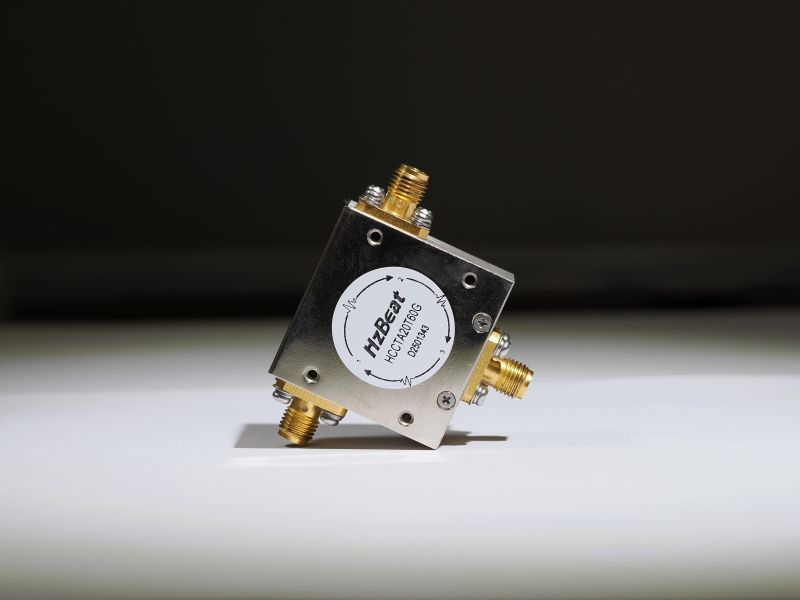
Compact radar, satellite communication, 5G, test and measurement, and high-power radio modules often leave very little space between an RF circulator and the rest of the electronics. That makes the question of magnetic components near RF circulators a real layout decision rather than a minor mechanical detail. A layout may look acceptable in CAD and still show higher insertion loss, weaker isolation or a shifted passband after the enclosure, power supply and mounting hardware are installed.
The safest engineering position is not that every magnetic component must be prohibited. It is that proximity must be treated as a controlled design variable. Component type, operating current, field direction, mounting material, shielding, temperature and the sensitivity of the selected circulator all matter. The following guidelines focus on placement and verification rather than circulator theory.
Which Nearby Components Require the Most Attention?
Power inductors and transformers
Switching power supplies are a common source of magnetic components near RF circulators. Shielded inductors usually produce less stray flux than open-core parts, but “shielded” does not mean zero leakage. Leakage can increase around an air gap, at high current or when the core approaches saturation. Transformers may also produce a time-varying field that changes with load.
Keep a high-current inductor or transformer away from the circulator body and RF ports. Avoid placing it directly beneath the circulator on the opposite side of a PCB, because the board itself provides almost no magnetic separation. If the power section must remain nearby, test at startup, light load, nominal load, current limit and the highest expected ambient temperature.
Motors, fans, relays and loudspeakers
Small motors, fans and loudspeakers often contain permanent magnets. Electromechanical relays combine magnetic material with an energized coil. These parts deserve more clearance than ordinary low-current shielded inductors. Their location may also change in a cable assembly or final enclosure, so review the full mechanical stack rather than the PCB alone.
Permanent magnets and magnetic connectors
Magnetic latches, magnetic charging connectors, mounting magnets and position-sensing magnets should be treated as strong local field sources. Moving a permanent magnet a few millimeters can materially change the field at the RF circulator. When the product includes a removable magnetic accessory, evaluate both its normal position and foreseeable worst-case positions.
Steel brackets, covers and screws
A component does not need to generate a field to cause concern. Ferromagnetic steel can redirect local flux and alter the environment around an RF circulator. Ordinary steel screws, sheet-steel brackets, spring clips and chassis parts should not be introduced late in production without a repeat test. HzBeat installation guidance recommends mounting circulators and isolators on a non-magnetic carrier or base.
Magnetic sensors and other sensitive devices
The interaction works in both directions. Hall sensors, magnetometers, electronic compasses and magnetic position sensors may be disturbed by the field around a conventional RF circulator. For those devices, the main risk may be sensor offset rather than degraded circulator performance. Place sensors using their own field-tolerance specification and verify them while the RF subsystem is assembled and operating.
How Much Spacing Is Required?
There is no universal safe distance for magnetic components near RF circulators. A fixed rule such as 5 mm, 10 mm or 25 mm can be either overly conservative or dangerously small. Required spacing depends on the circulator package, its magnetic shielding, the strength and orientation of the nearby field, the amount of ferromagnetic material, frequency range, bandwidth and allowable electrical drift.
Model-specific documents illustrate this variation. One Fairview Microwave millimeter-wave circulator datasheet instructs users to keep the device at least 0.2 inches from magnetic materials. That is approximately 5.08 mm, but it applies to the identified model and must not become a general rule for every coaxial, drop-in, SMD or waveguide circulator.
A Low Noise Factory datasheet reports the stray flux density for one shielded cryogenic circulator family at a defined distance and provides a minimum separation for two units of that family. It also defines external-field limits by the point at which passband shift and insertion-loss degradation become noticeable. This is the useful form of product data engineers should request: measurement distance, field orientation, shielding configuration and the electrical criterion used to define the limit.
Recommended RF Circulator Placement Strategy
1. Establish a preliminary keep-out area
Create a mechanical and PCB keep-out region around the RF circulator during the first layout, before space is consumed by the power supply or enclosure features. Include the volume above and below the board. Mark permanent magnets, motors, transformers, power inductors, relays and ferromagnetic structures as controlled items.
If supplier guidance is unavailable, begin with generous clearance and reduce it only after measurement. This approach gives the project a known-good baseline and makes later optimization much easier. It is particularly useful in broadband designs, where a small shift may affect one band edge before the center-frequency data appears abnormal.
2. Choose non-magnetic mounting materials
Use a non-magnetic carrier, baseplate and fasteners approved for the selected RF circulator. Aluminum, copper and brass are common candidates, subject to structural, corrosion and RF grounding requirements. Some stainless-steel grades are weakly magnetic after machining or cold working, so material names alone are not sufficient evidence.
Non-magnetic mounting must not compromise heat flow or grounding. A high-power RF circulator still needs a flat mounting surface, controlled fastener torque, a low-impedance RF ground and a thermal path suitable for forward and reflected power. Magnetic compatibility is one requirement within the complete installation, not a reason to ignore thermal and microwave requirements.
3. Prefer low-leakage magnetic parts
When power components must be nearby, compare their stray-field data rather than selecting only by inductance, current and package size. A closed magnetic path and a well-shielded package can reduce coupling. However, actual leakage depends on current and frequency, so test candidate inductors under the intended converter waveform.
4. Optimize orientation as well as distance
Magnetic coupling is directional. Rotating an inductor or changing the orientation of a motor may reduce the field component that matters at the circulator. Orientation can be a valuable tool when enclosure dimensions prevent additional spacing, but it must be verified. A favorable result in one axis does not prove tolerance to every assembly variation.
5. Avoid routing high-current loops through the keep-out area
Even components without a magnetic core can create a field when they carry current. Keep switching-current loops compact and away from the RF circulator. Route supply and return paths closely together to reduce loop area. Do not pass motor wiring, battery leads or pulsed load currents around the circulator housing simply because the schematic shows no direct connection.
| Nearby item | Primary layout concern | Recommended action |
|---|---|---|
| Shielded power inductor | Load-dependent AC leakage field | Increase spacing, optimize orientation and test at maximum current |
| Transformer | Leakage flux and load variation | Keep outside the initial keep-out area and test all operating modes |
| Motor or fan | Permanent magnet plus coil field | Use larger clearance and check actual installed orientation |
| Relay | Coil field and ferromagnetic frame | Separate from the circulator and test energized/de-energized states |
| Steel screw or bracket | Local flux redirection | Replace with verified non-magnetic hardware where specified |
| Hall sensor or compass | Sensor offset caused by circulator stray field | Follow sensor field limits and calibrate in the assembled product |
When Should Magnetic Shielding Be Used?
Magnetic shielding can help when packaging constraints leave limited space for magnetic components near RF circulators. High-permeability materials may guide low-level stray flux around a protected region, and some circulator manufacturers offer internal or optional external shields.
Shielding is not a universal cure. High-permeability material can saturate in a strong field, gaps and openings reduce performance, and adding material close to the circulator may itself alter the local magnetic path. Shield design also requires attention to mechanical stress, temperature, corrosion and manufacturability. Use shielding after the field source and coupling path have been characterized, then validate the shield in its production geometry.
Do not assume that a metal RF shield can also serve as a magnetic shield. Copper and aluminum are effective for many electric-field and high-frequency electromagnetic shielding tasks, but they do not provide the same low-frequency magnetic-flux path as a suitable high-permeability alloy.
How to Verify the Final Assembly
Visual inspection and spacing calculations are not enough. Verification should compare RF circulator performance before and after each relevant magnetic source or ferromagnetic structure is introduced.
- Measure the standalone circulator or the earliest available assembly and save insertion loss, isolation and return-loss traces across the full specified band.
- Install the intended baseplate, screws, cover and brackets. Repeat the measurement without changing cables or calibration reference planes.
- Add each nearby inductor, transformer, relay, motor or magnet at its final three-dimensional position. Test both powered and unpowered states.
- Operate variable magnetic components at minimum, nominal and maximum current, including startup, fault recovery and current-limit conditions.
- Repeat the comparison over the required temperature range. Include high-power operation when power or reflected energy can heat the circulator or nearby magnetic parts.
- Check all required forward paths, reverse isolation paths and return-loss parameters. Watch the band edges, not only a single center-frequency point.
- Move or rotate the suspected source to confirm that any observed change is repeatable and magnetically related rather than a connector or fixture error.
- Document the approved component, orientation, spacing, fastener material and shield configuration so production cannot substitute them silently.
A field probe or gaussmeter can add useful evidence, especially when comparing layout options. Record both field magnitude and direction at defined points around the RF circulator. The final acceptance criterion, however, should remain the RF performance and stability required by the system.
Design Review Checklist
- Has the exact circulator manufacturer supplied a magnetic placement or external-field limit?
- Are magnetic components near the RF circulator identified in both PCB and mechanical CAD?
- Does the keep-out review cover the space above and below the board?
- Are the carrier, cover, brackets, screws and assembly tools suitably non-magnetic?
- Have power inductors and transformers been tested at worst-case current and temperature?
- Have motors, relays and removable magnetic accessories been checked in every operating state?
- Has any magnetic shield been evaluated for saturation, openings and production tolerance?
- Were S-parameters measured after final enclosure assembly and at the required power level?
Frequently Asked Questions
Can an inductor be placed near an RF circulator?
Yes, but use a low-leakage shielded inductor, maximize separation and avoid placing it directly beneath the circulator. Verify the RF circulator at minimum and maximum inductor current, including startup and current-limit operation.
What is the safe distance between a circulator and magnetic components?
There is no universal safe distance. The correct value depends on the exact circulator, magnetic source, field orientation, shielding and permitted performance shift. Follow model-specific data and confirm the completed assembly by measurement.
Can steel screws be used to mount an RF circulator?
Ordinary ferromagnetic steel hardware should generally be avoided unless the circulator manufacturer approves it. Select verified non-magnetic fasteners while preserving RF grounding, mechanical strength and heat transfer.
Does magnetic shielding eliminate interference?
No. A shield can reduce low-level stray flux, but it may saturate in a strong field, and gaps or openings can reduce its effectiveness. Spacing, orientation and verification remain necessary.
Can two RF circulators be installed close together?
Some shielded product families permit close spacing, but the allowable distance is model-specific. Ask for the manufacturer’s circulator-to-circulator spacing data and verify isolation and insertion loss in the final orientation.
Conclusion
Magnetic components near RF circulators are acceptable only when proximity is deliberately engineered. Start with a conservative keep-out area, use verified non-magnetic mounting materials, select low-leakage power components, optimize orientation and avoid high-current loops around the housing. Where space is tight, evaluate purpose-designed magnetic shielding without treating it as a substitute for distance.
Most importantly, use the exact circulator datasheet and test the finished assembly. A distance that works for one product cannot be assumed safe for another frequency, package or shielding design. Comparing full-band S-parameters across operating current, temperature, power and mechanical configurations turns an uncertain placement decision into a controlled and repeatable RF design.
Need Help With RF Circulator Placement?
HzBeat supplies microstrip, drop-in, coaxial and waveguide RF circulators for communication, radar, SATCOM and test systems. Share your frequency band, power, available space, nearby magnetic sources and mounting structure for model-specific selection or customization support.
Visit HzBeat Official WebsiteTechnical References
- HzBeat: Circulators & Isolators Usage and Installation Guide
- Fairview Microwave FMCR1046 Product Datasheet
- Low Noise Factory: Circulator Magnetic Flux and External Field Data
- AFT Microwave: High-Power Circulator Installation Manual
Recommended Products
.jpg)
 Article Tags
Keith Wong
Marketing Director, Chengdu Hertz Electronic Technology Co., Ltd. (Hzbeat)
Keith has over 18 years in the RF components industry, focusing on the intersection of technology, healthcare applications, and global market trends.