Why RF Circulators Cannot Be Small, High-Power and Wideband
Explore why RF circulators struggle to combine small size, high power and wide bandwidth, from ferrite physics and thermal limits to practical RF design.
 Updated on: Jul 28, 2026
 Author:
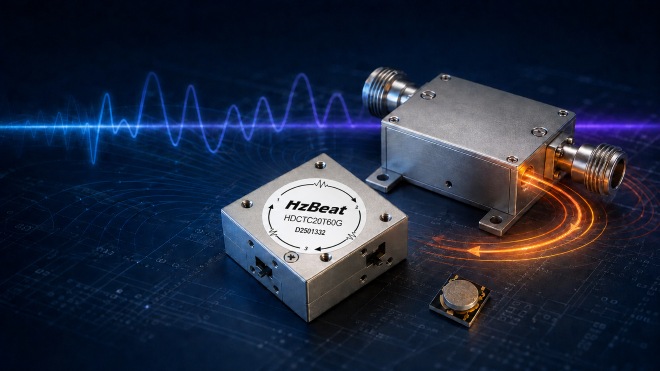
Introduction: A Three-Way Engineering Conflict
Modern radar, satellite communications, private wireless networks, test equipment and electronically steered arrays all place pressure on the RF front end. More channels must fit into less space. Transmitters are expected to deliver higher power or higher effective radiated power. At the same time, platforms increasingly need multiband or wideband operation. The circulator—often the component that lets a transmitter and receiver share an antenna while directing reflected energy away from sensitive circuitry—sits directly in the middle of these demands.
On a block diagram, a circulator looks simple: a three-port symbol with an arrow. In hardware, however, it is a distributed electromagnetic structure. A conventional junction circulator combines transmission lines, one or more ferrite elements, a magnetic bias system, conductors, grounding, a housing and carefully controlled impedance transitions. Its behavior depends on field patterns, material properties, geometry and temperature. Changing one part to improve footprint, power or bandwidth almost always changes the other two.
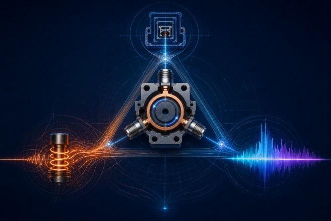
The Specifications That Reveal the Real Trade-Off
Size, rated power and frequency span are useful headline numbers, but they do not describe a circulator on their own. Engineers should read them alongside insertion loss, isolation, return loss or VSWR, connector or substrate interface, operating temperature and permitted load mismatch. A compact unit that reaches the desired frequency may still be unsuitable if its loss raises amplifier temperature or if its isolation deteriorates at the band edges.
Power ratings also require context. Continuous-wave and peak power stress a component differently, and a rating under a matched laboratory load may not represent operation with a highly reflective antenna. Pulse width, duty cycle, cooling surface, ambient pressure and allowable case temperature can all change the practical limit. Similarly, “wideband” should be expressed as a defined frequency range over which the insertion-loss, isolation and VSWR requirements are met at the same time.
The most informative comparison is therefore a performance envelope rather than a single best-case point. Buyers should request full-band S-parameter data, temperature behavior, power-test conditions and mechanical drawings. This approach exposes the compromises early and makes quotations from different RF circulator manufacturers meaningfully comparable.
Why a Miniature RF Circulator Is More Than a Packaging Exercise
At microwave frequencies, the dimensions of transmission-line structures are related to wavelength in the materials around them. A miniature RF circulator can reduce physical dimensions through higher-permittivity dielectrics, slow-wave structures, junction loading or multilayer layouts. A ferrite with suitable magnetic properties can also help concentrate the interaction. Yet electromagnetic miniaturization normally increases stored energy relative to transmitted energy, raising the effective quality factor and making the response more resonant.
A strongly resonant device can perform very well near its design frequency but deteriorate more rapidly away from it. Small geometrical errors then represent a larger fraction of critical dimensions. Tolerance in ferrite thickness, metallization, dielectric constant, air gaps, adhesive layers or magnet placement can shift the center frequency and change the isolation null. Manufacturing consistency therefore becomes harder just when the structure becomes less forgiving.
Miniaturization also reduces conductor width and ground area, which can increase current density and ohmic loss. Smaller housings have less external surface area and less thermal mass. Compact layouts may place ports, matching elements and magnets closer together, increasing unintended coupling. At high frequencies, connector launches and transitions can consume a meaningful fraction of the entire loss and size budget. A miniature RF circulator may shrink externally, but its electromagnetic and thermal requirements do not shrink at the same rate.
Why a High-Power RF Circulator Pushes Design in the Opposite Direction
A high-power RF circulator cannot be defined by one power number. Continuous-wave power is often limited by average heating, while pulsed operation can be limited by peak electric or magnetic fields even when average heat is modest. A severe load mismatch can send substantial reflected power into the circulator and its termination, so a robust design must consider the expected VSWR, pulse width, duty cycle, altitude and cooling conditions—not merely the transmitter's nominal output.
Loss that appears small in decibels can become a significant thermal load at high power. If a component dissipates even a small percentage of a kilowatt-class signal, that loss becomes heat inside the ferrite, conductors and interfaces. Temperature rise can change saturation magnetization, permeability and resonance conditions. The circulation response then moves away from its optimum point, potentially increasing loss further. Without sufficient thermal margin, this feedback can erode performance or reliability.
Peak fields create other constraints. Closely spaced conductors and sharp edges increase electric-field intensity, which can raise breakdown or multipactor concerns in specialized environments. High RF magnetic fields can approach nonlinear operating regions in the ferrite, producing loss, distortion or intermodulation. Designers respond with greater ferrite volume, wider conductors, smoother transitions, more generous spacing, better heat spreading and heavier housings. Every one of those remedies fights the requirement for minimum size and mass.
Material selection matters, but no material cancels geometry. A ferrite composition may offer an attractive combination of saturation magnetization, linewidth, dielectric properties and temperature behavior, yet the complete assembly must still remove heat and control fields at interfaces. The rating of a high-power RF circulator is therefore a system property, not simply a ferrite data-sheet value.
Why a Wideband RF Circulator Is Hard to Optimize
A wideband RF circulator must preserve phase and amplitude relationships among its junction modes across the specified range. Those relationships vary with frequency because the electrical length of the transmission lines, the ferrite response and the impedance of each discontinuity vary. A basic junction may therefore provide its best match and isolation across only a limited fractional bandwidth.
Engineers can broaden the response with multi-section transformers, dielectric loading, additional resonances, shaped ferrite elements, multiple junctions or more elaborate matching networks. These approaches can flatten performance, but they consume area and introduce more interfaces and tolerance-sensitive dimensions. Cascaded or multi-resonant designs may also add insertion loss, while extra dielectric and conductor volume must survive the same power stress.
Bandwidth specifications also require careful interpretation. A vendor may define the band by maximum insertion loss, minimum isolation and maximum VSWR simultaneously. Broadening one curve does not guarantee that all three limits are met over the same range. In a practical radio, group delay, phase tracking, intermodulation and temperature drift may narrow the useful range of a wideband RF circulator further.
The result is a familiar trade: compact resonant loading helps reduce size but tends to narrow the response; broadband matching increases size and complexity; high-power spacing and thermal construction increase volume again. The three goals form a triangle rather than three independent checkboxes.
| Priority | What the design tends to need | Typical pressure on the other goals |
|---|---|---|
| Small size | High loading, compact junctions, tighter integration and reduced magnetic volume | Higher field density, harder cooling, tighter tolerances and potentially narrower bandwidth |
| High power | Low loss, wider conductors, adequate ferrite volume, field clearance and strong heat paths | Larger housing, greater mass and more difficult broadband matching |
| Wide bandwidth | Multi-resonant behavior, broadband transitions and additional matching sections | More area, added interfaces, increased complexity and sometimes greater loss |
RF Circulator Manufacturers Take Different Routes to the Same Trade-Off
The supplier landscape is broader than any one materials company. TDK remains relevant as a major source of ferrite and ceramic materials knowledge, but system designers typically evaluate specialist ferrite circulator manufacturers whose portfolios include complete drop-in, coaxial, microstrip, surface-mount or waveguide assemblies. Each supplier emphasizes a different balance of catalog availability, customization, environmental qualification, frequency coverage and power handling.
HzBeat: multiple form factors and application-specific customization
HzBeat focuses on passive microwave RF components and presents product families spanning microstrip, drop-in, coaxial, waveguide and dual-junction formats. For compact modules and phased-array integration, designers can review the HzBeat microstrip circulator range. Embedded assemblies can start with its drop-in circulators, while connectorized test, telecom and radar paths may be better matched to coaxial circulators. Applications prioritizing low loss or elevated power at microwave and millimeter-wave frequencies can explore waveguide circulators.
These links are internal to the HzBeat website and help readers move from the engineering discussion to the relevant mechanical platform. HzBeat also advertises customization and test reporting, which matters because size, bandwidth and power targets often cannot be resolved by selecting a generic catalog part. Final suitability still depends on verified model-level specifications and the actual thermal and mismatch conditions of the system.
Smiths Interconnect
Offers waveguide, coaxial, stripline, microstrip and SMT ferrite devices, including products aimed at aerospace, defense and space-qualified applications.
DiTom Microwave
Focuses on in-stock and high-reliability isolators and circulators, with dedicated cryogenic, military, TVAC and space-oriented options.
JQL Technologies
Supplies RF and microwave components including coaxial and SMT circulators for wireless, public-safety and satellite markets.
UIY
Lists a broad component portfolio across coaxial, drop-in, microstrip and surface-mount formats over a wide frequency range.
Renaissance Electronics
Develops RF, microwave and millimeter-wave components, including custom circulators and waveguide products for demanding systems.
Raditek
Provides RF and microwave circulator options in several transmission formats, including microstrip and application-specific configurations.
A fair supplier comparison should not rank companies by one published maximum. Instead, compare the exact operating band, full-band insertion loss and isolation, CW and peak-power test conditions, mismatch survival, temperature range, mechanical interface, qualification evidence, lead time and customization support. This makes the selection technically useful rather than promotional.
Different Applications Choose Different Winners
5G, private networks and compact radios
Dense radio units prioritize footprint, cost and manufacturability. The circulator must coexist with filters, power amplifiers, antenna feeds and control electronics in a thermally crowded enclosure. Designers may accept a band-specific component or use multiple signal paths because a single ultra-wideband, high-power device would be too large or inefficient.
Radar and electronic warfare
Radar systems can place a premium on peak-power survival, isolation and low loss. The cost of allowing transmit energy into a sensitive receiver may be far greater than the cost of extra component volume. Waveguide or larger stripline architectures remain attractive where power and reliability dominate, even if they conflict with aggressive miniaturization.
Satellite and aerospace platforms
Space systems value low mass, but thermal paths, vacuum behavior, radiation environment and multipactor margins complicate the picture. Qualification across temperature can expose magnetic drift and mechanical-stress effects that a room-temperature data sheet does not show. A smaller component is useful only if it remains predictable throughout the mission environment.
Test and measurement
Broadband instrumentation favors frequency coverage and calibrated stability. Designers may accept lower power or a physically larger assembly to avoid changing hardware between bands. The appropriate compromise therefore follows the use case; there is no universal ranking of the three goals.
What Could Shift the Balance?
Future gains are likely to arrive through co-optimization rather than one breakthrough. Lower-loss ferrites and better temperature compensation can reduce the thermal penalty. Additive and multilayer manufacturing may enable three-dimensional field shaping that uses volume more efficiently. Improved permanent magnets can deliver the required bias in a more compact magnetic circuit. Advanced heat spreaders and direct attachment to cooled structures can increase continuous-wave capability without proportionally enlarging the RF junction.
At the architecture level, designers can distribute the problem. Instead of forcing one circulator to cover every band and power condition, a system may switch among optimized paths, combine filtering and circulation functions, or use balanced amplifier architectures that tolerate reflections differently. Active or time-varying non-reciprocal circuits offer integration opportunities, particularly for full-duplex radios, but they introduce their own challenges in noise, linearity, power consumption, switching products and transmitter-power tolerance.
For procurement teams, the practical lesson is to avoid asking only for “the smallest wideband high-power circulator.” A useful request for quotation should specify the frequency range; insertion-loss, isolation and VSWR limits; continuous and peak forward power; pulse format; maximum reflected power; load mismatch; operating temperature; cooling interface; connector or substrate environment; and allowable size and mass. Those details let the supplier identify which constraint is truly dominant.
Conclusion
RF circulators struggle to be small, high-power and wideband simultaneously because each objective asks the physical structure to behave differently. A miniature RF circulator concentrates electromagnetic energy and heat while increasing sensitivity to tolerances. A high-power RF circulator calls for low loss, larger conductors, adequate magnetic volume, voltage clearance and efficient cooling. A wideband RF circulator requires field and impedance relationships to remain controlled over frequency, often through additional matching structures that add size and complexity.
Advanced ferrites, ceramic processing and component integration can improve the available choices, while specialist suppliers such as HzBeat, Smiths Interconnect, DiTom, JQL, UIY, Renaissance Electronics and Raditek translate ferrite circulator technologies into different product formats. None of them can repeal the underlying physics. The best circulator is therefore not the one that claims to maximize all three headline attributes; it is the one whose size, bandwidth, loss, isolation, temperature stability and power behavior are honestly optimized for the complete RF system.
Frequently Asked Questions
What is an RF circulator?
An RF circulator is a passive non-reciprocal device that sends energy from each port to the next port in a defined sequence. A three-port unit can allow a transmitter and receiver to share an antenna while routing reflected energy toward a load or another protected path.
Why are high-power RF circulators usually larger?
High-power units need enough conductor area, ferrite volume, voltage spacing and thermal capacity to control current density, peak fields and temperature rise. Those requirements generally demand more physical volume.
Why does miniaturization often reduce bandwidth?
Compact designs commonly rely on stronger electromagnetic loading and more resonant structures. Their impedance and circulation conditions can then change more quickly with frequency, unless extra broadband matching is added.
Can one circulator cover several communication bands?
It is possible in some systems, but the required fractional bandwidth, isolation, power and size determine whether a single device is practical. Switched paths or multiple optimized circulators may provide a better system solution.
What specifications matter besides frequency and power?
Insertion loss, isolation, return loss or VSWR, continuous versus peak power, pulse duty cycle, reflected-power tolerance, intermodulation, temperature range, thermal interface and mechanical transitions all matter.
Which companies manufacture RF circulators?
Examples include HzBeat, Smiths Interconnect, DiTom Microwave, JQL Technologies, UIY, Renaissance Electronics and Raditek. Their catalogs, customization services and qualification capabilities differ, so selection should follow the application's frequency, power, bandwidth, interface and environment.
Are magnet-free circulators a complete replacement?
Not yet for every use case. Active, switched and time-varying approaches can be highly integrated, but they must be evaluated for linearity, noise, spurious signals, power consumption and tolerance of strong transmitter signals.
References and Further Reading
- TDK Electronics, Ferrites and Accessories Product Catalog. Official overview of ferrite materials and related product resources.
- HzBeat, RF Circulators and Isolators. Official product-family overview covering microstrip, drop-in, coaxial, waveguide and dual-junction formats.
- Smiths Interconnect, Isolators and Circulators. Official ferrite component portfolio.
- DiTom Microwave, RF Isolators and Circulators. Official overview of catalog and high-reliability product categories.
- JQL Technologies, Company and RF/Microwave Product Overview.
- UIY, RF Circulator and Isolator Portfolio.
- Renaissance Electronics, RF and Microwave Product Catalog.
- Raditek, Circulator Product Overview.
- IEEE Technology Navigator, Waveguide Components. Background on non-reciprocal ferrite junctions, circulators and high-power microwave use.
- IEEE Technology Navigator, Microwave Magnetics. Overview of gyromagnetic ferrite behavior and non-reciprocal devices.
- NASA Technical Reports Server, The Effect of Temperature Variation on Ferrite Circulator Operation. Technical discussion of temperature-dependent magnetic properties and Wye-junction operation.
- H. Bosma, “On Stripline Y-Circulation at UHF,” IEEE Transactions on Microwave Theory and Techniques, vol. 12, no. 1, 1964, pp. 61–72.
- D. M. Pozar, Microwave Engineering, 4th ed., Wiley, 2011. General reference for microwave networks, ferrite devices, matching and resonators.
- J. Helszajn, Nonreciprocal Microwave Junctions and Circulators, Wiley, 1975. Foundational treatment of circulator theory and design.
Editorial note: This technical article is provided for general information and SEO publishing. Manufacturer names are included for market context; inclusion does not establish equivalence among products or replace model-level engineering review. Verify all decisions against current manufacturer data and application testing. Replace the example canonical URL, publisher name and publication details before deployment.
Recommended Products
.jpg)
 Article Tags
Keith Wong
Marketing Director, Chengdu Hertz Electronic Technology Co., Ltd. (Hzbeat)
Keith has over 18 years in the RF components industry, focusing on the intersection of technology, healthcare applications, and global market trends.