How Does Temperature Affect RF Circulator Performance?
Learn how temperature affects ferrite RF circulators, including center-frequency drift, insertion loss, isolation, VSWR, bandwidth, power handling, and reliability.
 Updated on: Jul 31, 2026
 Author:
Temperature changes can shift an RF circulator's operating frequency, increase insertion loss, reduce isolation, worsen impedance matching, and narrow its safe power margin. This in-depth guide focuses on measurable performance changes, qualification testing, product selection, and the risks engineers must control in demanding RF systems.
Introduction
As wireless infrastructure, satellite links, radar platforms, and high-power RF equipment move toward higher frequencies and harsher environments, RF circulator temperature performance has become a critical part of component qualification. A device that looks excellent at 25°C may behave differently at the cold start of an outdoor radio, inside a hot airborne enclosure, or after prolonged exposure to reflected power.
The practical question is not simply whether an RF circulator can operate across a specified temperature range. Engineers need to know how much its insertion loss, isolation, VSWR, center frequency, bandwidth, and power capability change at each temperature extreme—and whether those changes still leave enough system margin.
This article examines those measurable effects without repeating basic circulator theory. It also explains how to read full-temperature data, structure a meaningful test plan, compare candidate components, and avoid common mistakes that turn a small laboratory drift into a system-level reliability problem.
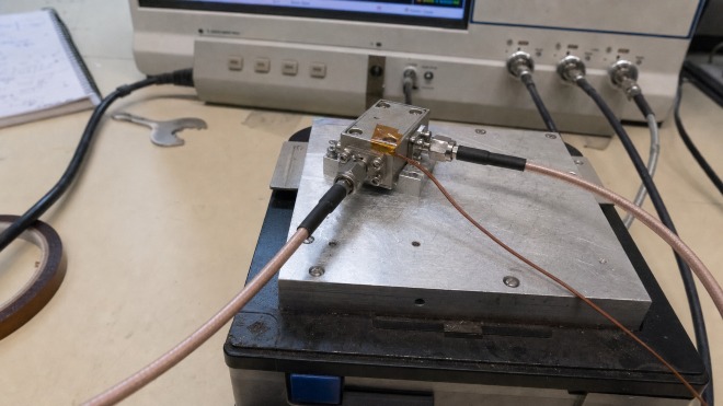
- Room-temperature typical values are not enough for serious RF circulator selection.
- Insertion loss, isolation, center frequency, VSWR, and bandwidth must be compared across the full operating range.
- Ambient temperature and the circulator's actual case temperature are rarely identical at high power.
- Band-edge channels and reflected-power events usually expose temperature margin first.
- A useful qualification combines temperature, RF power, mismatch, mounting, and thermal soak time.
Start With the Real Temperature Profile
Ambient temperature is only the first number
The temperature printed in an environmental specification normally refers to ambient air, but RF circulator temperature performance depends more directly on the temperature of the installed component. A circulator near a power amplifier, inside a sealed enclosure, or mounted on a weak thermal path may run substantially hotter than the surrounding air.
Cold start and hot steady state are different test conditions
A cold-start measurement captures the first minutes after power-up, while a hot steady-state measurement captures the condition reached after losses and reflected power have heated the assembly. Both matter. A radio can pass a brief chamber sweep yet fail after an hour at full duty cycle because the RF circulator case temperature continues to rise after the chamber sensor has stabilized.
Thermal gradients can hide local hot spots
The mounting flange, ferrite junction, connector body, and external load do not necessarily reach the same temperature. At high power, engineers should record case temperature at the specified reference point and inspect the termination or heat spreader for local hot spots. A single chamber reading cannot describe the complete thermal condition.
1. Center-Frequency Drift
Why band-edge channels deserve special attention
A circulator normally delivers its best combination of low insertion loss, high isolation, and good return loss around a designed center frequency. When ferrite magnetization or magnetic bias changes, the optimum operating point can shift along the frequency axis.
A small shift may be acceptable in a broadband device. In a narrowband, high-isolation, or millimeter-wave design, however, even modest drift can move the system frequency away from the optimum region. The center of the isolation response may shift, insertion loss may rise at the original frequency, and one edge of the specified band may no longer meet its limit.
The direction and magnitude of the drift are not universal. They depend on ferrite composition, magnetic-circuit design, frequency range, geometry, and any built-in temperature compensation. Manufacturer-supplied data over the complete temperature range should therefore take priority over a generic rule of thumb.
How to evaluate frequency drift
Plot isolation, insertion loss, and return loss on the same frequency axis for every temperature point. Then compare the movement of each response against the actual channel plan. A single value quoted at the nominal center frequency can conceal failure at the upper or lower channel. For a tunable or multi-band radio, repeat the comparison at every operating state.
2. Higher Insertion Loss
Small dB changes become meaningful at system level
Insertion loss measures the signal power lost between the input port and the intended output port. Temperature can increase insertion loss by changing magnetic loss, raising conductor resistance, altering dielectric loss, and moving the device away from its optimum impedance and resonance conditions.
A recent high-power study of S-band stripline circulators illustrates why material choice matters. For one ferrite implementation, measured insertion loss increased from approximately 0.38 dB to 0.64 dB during the test. A second material showed a larger change, from approximately 0.63 dB to 1.30 dB. The results demonstrate that two devices with similar thermal conditions can retain RF performance very differently because of their ferrite material and design.
Higher insertion loss also creates a feedback concern: more lost RF energy is converted to heat, which can raise device temperature and cause further degradation.
Convert insertion loss into heat and link-budget impact
Do not evaluate a loss increase only as a small decimal change. Translate it into lost transmitter power, reduced EIRP, added receiver noise figure, and heat generated inside the RF circulator. This conversion is particularly important in high-duty-cycle radar and satellite transmitters, where a few tenths of a decibel can materially change the thermal balance.
3. Reduced Isolation
Receiver protection is often the limiting requirement
Isolation indicates how effectively the circulator prevents energy from reaching an undesired port. In a shared-antenna transceiver, for example, the circulator must direct transmitter power toward the antenna while limiting leakage into the sensitive receiver path.
High isolation depends on the correct magnetic state and a precise balance of signal amplitude and phase. Temperature-induced detuning can prevent unwanted waves from cancelling fully at the isolated port. Isolation then falls, even if forward transmission still appears acceptable.
Reduced isolation can lead to:
- More transmitter leakage into the receiver;
- Receiver compression, desensitization, or damage;
- Higher self-interference in full-duplex systems;
- Reduced radar dynamic range and weak-target sensitivity;
- Greater exposure of the power amplifier to reflected signals.
Isolation over temperature is therefore particularly important in radar, base-station, satellite, and common-antenna transmit/receive architectures.
Check absolute leakage power, not isolation alone
The same isolation value has very different consequences at 1 W and 1 kW. Convert the worst-case full-temperature isolation into absolute leakage power and compare it with receiver compression, limiter, and damage limits. This exposes whether the RF circulator still protects downstream hardware during the hottest operating condition.
4. Degraded Return Loss and VSWR
Mismatch affects both performance and temperature
Most RF circulators are designed for a nominal 50-ohm environment. Temperature-dependent material properties and thermal expansion can shift the port impedance away from its intended value. The result may be poorer return loss and a higher voltage standing-wave ratio, or VSWR.
A mismatch sends more energy back toward the source. This reduces delivered power and can increase stress on the power amplifier, circulator, and terminating load. The risk becomes more significant at high power because reflected energy contributes additional heat.
Measure all ports with representative terminations
Full-temperature testing should verify every relevant port, not only the nominal input. Test cables, adapters, and external loads must have adequate return loss and power capacity, otherwise the fixture can create apparent RF circulator temperature drift that does not belong to the device itself.
5. Changes in Usable Bandwidth
Specified bandwidth and qualified bandwidth are not always equal
A circulator's usable bandwidth is normally defined by several limits at once, such as maximum insertion loss, minimum isolation, and maximum VSWR. Temperature can shift or reshape all three responses, reducing the portion of the band that meets system requirements.
A device may cover the target band at room temperature but fail an isolation limit near a band edge at its minimum or maximum rated temperature. For this reason, a headline frequency range should not automatically be treated as a guarantee of identical performance across the entire thermal range.
Define bandwidth using simultaneous limits
The qualified band should be the frequency range in which insertion loss, isolation, return loss, and power requirements are all satisfied at every required temperature. Reporting each parameter's best bandwidth separately can overstate the range that the complete RF system can actually use.
6. Power Handling and Long-Term Reliability
Forward power and reflected power create different stresses
In a high-power RF system, ambient temperature is only part of the thermal picture. Ferrite, conductor, and dielectric losses generate heat during normal transmission. Reflected power from a mismatched antenna or load may also be routed into an attached termination and create a concentrated heat source.
If heat is not removed effectively, the internal temperature can be much higher than the surrounding air or equipment chassis. Prolonged exposure may reduce permanent-magnet strength, age adhesives and seals, fatigue solder joints, and shorten connector or load life.
Approaching a ferrite material's Curie temperature is especially dangerous because its ordered magnetic state deteriorates. The circulator may then lose the nonreciprocal behavior required for correct signal routing.
Very low temperature is not automatically beneficial either. Cryogenic operation changes magnetic parameters, mechanical dimensions, and contact behavior. Research on single-crystal yttrium iron garnet across temperatures from 300 K down to 2 K underscores the need to characterize materials and devices specifically for cryogenic service rather than assuming that a standard commercial unit will behave normally.
Thermal cycling can reveal failures that a static test misses
A circulator may meet electrical limits at both temperature extremes but still develop drift after repeated cycling. Expansion and contraction can affect mounting pressure, solder joints, bonded interfaces, connectors, and the external load. Qualification for airborne, vehicle, and outdoor systems should therefore include repeated cycles and a room-temperature baseline check after the final cycle.
Application-Specific Temperature Risks
Radar and electronic warfare systems
Pulsed peak power, rapid duty-cycle changes, and wide instantaneous bandwidth can expose both thermal and RF limits. The important checks are worst-case isolation into the receiver, pulse insertion loss, load temperature during mismatch, and recovery after a high-power event.
Satellite and airborne equipment
These systems combine broad temperature excursions with restricted cooling and strict mass limits. Conductive thermal paths, mounting flatness, vibration, and thermal cycling deserve the same attention as room-temperature RF data. Component qualification should use the actual installation interface.
5G, 6G, and compact radio modules
Dense integration places the RF circulator close to power amplifiers and digital heat sources. Compact housings can develop gradients that are not visible in an ambient specification. Designers should model the complete module and verify the circulator's case temperature at maximum traffic load.
Outdoor and industrial wireless systems
Solar loading, sealed cabinets, winter cold start, fan aging, and dust-clogged filters can push the actual RF circulator temperature beyond the assumptions used during initial design. Field-oriented qualification should include realistic enclosure and airflow conditions.
How to Read an RF Circulator Datasheet for Temperature Performance
Separate typical values from guaranteed limits
A typical value is useful for estimating nominal performance but may not be guaranteed for every unit or temperature. Procurement specifications should identify which limits apply across the full operating range and which are valid only near room temperature.
Look for test conditions behind every power rating
Forward-power and reflected-power ratings depend on frequency, duty cycle, mounting temperature, load VSWR, airflow, and test duration. A high headline number is not meaningful unless those conditions match the intended system.
Match construction style to the thermal path
Drop-in, microstrip, SMT, coaxial, and waveguide products transfer heat into the system differently. Engineers comparing available formats can review the HzBeat RF circulator and isolator range and then request full-temperature data for the exact package, frequency band, and mounting configuration under review.
Request data at the actual frequencies of interest
A few marker values may be insufficient for a wideband or channelized system. Ask for full S-parameter sweeps at the minimum, nominal, and maximum case temperatures. If a connectorized unit is being considered, the practical selection points discussed in HzBeat's overview of coaxial RF circulators can help frame connector, mounting, power, and integration requirements.
How to Minimize Temperature-Related Degradation
- Select the correct temperature grade. The rated range should cover ambient extremes, internal self-heating, and nearby heat sources.
- Request full-temperature S-parameter data. Review insertion loss, isolation, return loss, VSWR, center frequency, and bandwidth at the minimum and maximum operating temperatures—not only at 25°C.
- Maintain design margin. Avoid placing the operating channel directly at the edge of the circulator's usable band, and allow margin in isolation, loss, forward power, and reflected-power capacity.
- Provide an effective thermal path. A flat metal mounting surface, suitable interface material, adequate clamping, heat sinking, and airflow can lower the device's steady-state temperature.
- Control load mismatch. Verify antenna and load VSWR and consider fault cases such as an open or short circuit. Confirm that both the circulator and termination can tolerate the resulting reflected power.
- Combine temperature and power testing. Low-power chamber measurements may not reveal high-power self-heating. Test under realistic frequency, RF power, mismatch, mounting, airflow, and duty-cycle conditions.
- Use compensated designs when needed. Ferrite selection, magnet design, matching networks, and temperature-compensation techniques can improve stability in demanding systems.
When a standard catalog part does not provide enough temperature margin, custom bandwidth, isolation, package, and thermal requirements should be defined together rather than optimized independently. HzBeat describes its available customization and environmental-validation capabilities in its RF circulator manufacturing overview. Final performance should still be confirmed against the approved product specification and application-level qualification data.
Recommended Temperature-Test Procedure
A practical qualification sequence should include the following steps:
- Calibrate the vector network analyzer at the intended reference planes.
- Mount the circulator using the production thermal and mechanical arrangement.
- Attach a calibrated temperature sensor close to the ferrite junction or specified case-temperature point.
- Measure S-parameters at room temperature to establish a baseline.
- Move through the required temperature points and allow adequate soak time at each point.
- Record insertion loss, isolation, return loss, VSWR, center frequency, and usable bandwidth.
- Repeat under representative forward and reflected power when the application is power sensitive.
- Return to room temperature and check for permanent drift or hysteresis.
Measurement cables and calibration standards can also drift with temperature. They should be kept outside the chamber where practical, stabilized before measurement, or characterized separately so that cable behavior is not mistaken for circulator drift.
Minimum data to record at every temperature point
- Ambient, fixture, and RF circulator case temperature;
- Soak time and evidence that thermal equilibrium was reached;
- Insertion loss, isolation, return loss, VSWR, and center frequency;
- Forward power, reflected power, duty cycle, and load condition;
- Supply and airflow conditions for nearby active hardware;
- Calibration method, cable arrangement, and measurement uncertainty;
- Visual inspection results before and after thermal cycling.
Use pass/fail limits that reflect the complete system
A component-level pass limit should connect directly to system performance. Maximum RF circulator insertion loss should preserve the link budget; minimum isolation should keep leakage below receiver limits; maximum VSWR should remain safe for the power amplifier; and the load temperature should stay below its reliability limit. This approach prevents a test report from passing every individual number while the assembled radio still lacks margin.
RF Circulator Temperature-Performance Selection Checklist
Electrical requirements
- Operating band and channel-edge frequencies;
- Maximum insertion loss across temperature;
- Minimum isolation across temperature;
- Maximum input and output VSWR;
- CW, pulsed, peak, and average power;
- Expected antenna or load mismatch.
Thermal and environmental requirements
- Minimum and maximum ambient temperature;
- Maximum allowable circulator case temperature;
- Heat-sink material, flatness, interface material, and clamping method;
- Airflow, enclosure sealing, altitude, and nearby heat sources;
- Thermal-cycle count, vibration, shock, and humidity requirements.
Evidence to request from the supplier
- Full-temperature S-parameter plots or Touchstone files;
- Definition of typical versus guaranteed specifications;
- Power-rating conditions and thermal mounting instructions;
- Lot acceptance, screening, and traceability options;
- Custom test data for nonstandard temperature or mismatch conditions.
Common Mistakes in Temperature Qualification
Testing only at 25°C
Room-temperature data cannot demonstrate RF circulator temperature performance. At minimum, verify the cold, nominal, and hot conditions, with additional points where the response changes rapidly or system margin is small.
Using chamber air temperature as device temperature
Measure the specified case location. Chamber air can stabilize long before a heavy fixture, termination, or heat spreader reaches equilibrium.
Ignoring the test fixture
Cable movement, adapter drift, fixture expansion, and poor load match can imitate changes in the RF circulator. Stabilize and characterize the setup, and use port extension or de-embedding where appropriate.
Testing temperature and power separately
A chamber sweep at low power and a power test at room temperature do not reproduce the combined worst case. The most useful validation applies the expected thermal environment, RF power, duty cycle, and mismatch together.
Checking specifications without system margin
Passing a catalog limit does not guarantee a robust design. Include production spread, aging, calibration uncertainty, cable and antenna variation, thermal interface degradation, and realistic fault conditions in the margin analysis.
Conclusion
Temperature affects an RF circulator through changes in ferrite magnetic properties, bias field, conductor and dielectric loss, and mechanical dimensions. The resulting performance changes may include center-frequency drift, higher insertion loss, lower isolation, worse VSWR, reduced usable bandwidth, and lower power-handling margin.
The exact magnitude and direction of these changes depend on the material, magnetic circuit, geometry, frequency band, and compensation strategy. Engineers should therefore evaluate full-temperature data and realistic thermal-power testing instead of relying only on typical room-temperature specifications.
For general communications equipment, a properly rated circulator with adequate margin may be sufficient. High-power, millimeter-wave, radar, aerospace, and cryogenic applications require closer attention to S-parameter stability, mismatch survival, thermal design, and long-term reliability.
Frequently Asked Questions
Does a rise in temperature always cause an RF circulator to fail?
No. A circulator should continue to operate within its specified temperature range, although insertion loss, isolation, VSWR, and center frequency may change. Serious degradation or permanent damage becomes more likely when the maximum rated temperature is exceeded.
Does a circulator always perform better at a lower temperature?
No. Lower conductor resistance may help in some cases, but low temperature also changes ferrite magnetic properties, bias conditions, mechanical dimensions, and connector behavior. A standard commercial circulator may shift away from its design point.
Which parameters are most sensitive to temperature?
Commonly affected parameters include center frequency, insertion loss, isolation, return loss, VSWR, bandwidth, and power handling. Narrowband designs may be especially sensitive to frequency and isolation drift, while high-power designs require close attention to loss and self-heating.
Is ambient temperature the same as the circulator's actual temperature?
Usually not. RF losses create self-heating, and nearby amplifiers, power supplies, restricted airflow, and reflected power can raise the case and junction temperature above ambient. Thermal design should use measured or modeled device temperature rather than ambient alone.
How can temperature drift be measured?
Measure S-parameters with a calibrated vector network analyzer while the device temperature is controlled and recorded. Allow thermal stabilization at every set point and compare center frequency, S11, forward transmission, and isolation-port response. High-power applications should also be tested at representative power and mismatch levels.
Why does a circulator heat up at high RF power?
Ferrite, conductor, and dielectric losses convert part of the transmitted RF energy into heat. Reflected power from a mismatched antenna or load may add substantial heat to the termination and device assembly.
What should buyers check when selecting a wide-temperature circulator?
Check the rated temperature range, maximum full-temperature insertion loss, minimum isolation, maximum VSWR, center-frequency drift, forward-power and reflected-power ratings, mounting requirements, and the thermal resistance of the intended installation.
References
- “Broadband S-Band Stripline Circulators: Design, Fabrication, and High-Power Characterization.”
- H. Wang et al., “An Integrated Miniaturized Self-Biased Circulator Based on the Low-Temperature D2W Bonding Technique,” Electronics Express, 2025.
- A. Ashley, D. Psychogiou, and Z. Popović, “Bandwidth Design of Ferrite-Based Circulators.”
- “Low Loss Ferrite Y-Junction Circulator Based on Empty Substrate Integrated Coaxial Line at Ku-Band,” including temperature measurements from 20°C to 90°C.
- “Evaluation of Circular Complex Permeability in Single-Crystal Yttrium Iron Garnet at Cryogenic Temperatures.”
- HzBeat, “What Is a Coaxial Circulator?”
- HzBeat, “Leading China RF Circulator Manufacturer & Supplier.”
Recommended Products
.jpg)
 Article Tags
Keith Wong
Marketing Director, Chengdu Hertz Electronic Technology Co., Ltd. (Hzbeat)
Keith has over 18 years in the RF components industry, focusing on the intersection of technology, healthcare applications, and global market trends.