RF Circulator vs Duplexer: What’s the Difference?
RF circulator vs duplexer: learn the key differences in working principle, Tx/Rx separation, insertion loss, isolation, applications, and how to choose the right RF component.
 Updated on: Aug 20, 2026
 Author:
In RF and microwave systems, both RF circulators and duplexers can be used to manage signals between transmit and receive paths. Because both devices may appear near the antenna or RF front end, they are sometimes assumed to perform the same function.
However, an RF circulator and a duplexer operate on fundamentally different principles.
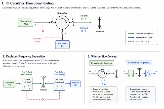
Key Difference: An RF circulator routes RF energy according to signal direction, while a duplexer separates transmit and receive signals according to frequency.
Understanding this difference is important when designing radar systems, communication equipment, transceivers, satellite systems, and other RF front ends.
What Is an RF Circulator?
An RF circulator is typically a three-port non-reciprocal passive component that routes RF energy sequentially from one port to the next.
Typical signal flow: Port 1 → Port 2 → Port 3 → Port 1
This means that a signal entering Port 1 is primarily directed to Port 2, while Port 3 is isolated from Port 1. Because of this directional behavior, an RF circulator can allow a transmitter and receiver to share the same antenna while helping prevent transmitted power from directly entering the receiver.
In practical RF systems, circulators may also be used for:
- Transmit/receive signal routing
- Power amplifier protection
- Reflected power management
- Antenna sharing
- RF path isolation
- Test and measurement systems
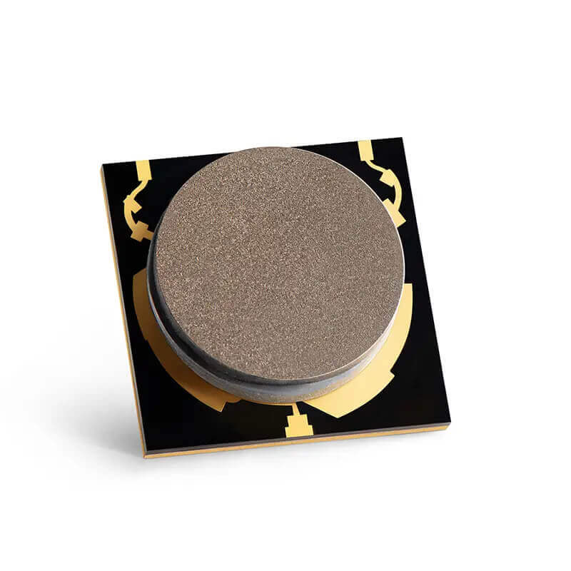
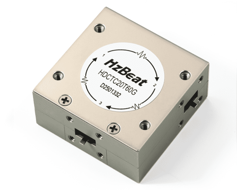
RF circulators are available in coaxial, drop-in, microstrip, surface-mount, and waveguide structures depending on frequency, power, integration, and mechanical requirements.
What Is a Duplexer?
A duplexer is a frequency-selective RF device that allows two different frequency bands to share a common antenna or RF path.
It normally contains filters designed for separate transmit and receive frequency bands. The transmit filter passes the TX band toward the antenna while suppressing the RX band, while the receive filter passes the RX band toward the receiver while rejecting the TX band.
Duplexers are especially common in FDD (Frequency Division Duplex) communication systems where transmit and receive signals operate simultaneously at different frequencies.
RF Circulator vs Duplexer: Key Differences
| Parameter | RF Circulator | Duplexer |
|---|---|---|
| Operating Principle | Non-reciprocal signal routing | Frequency-selective filtering |
| Typical Ports | 3 ports | TX, RX and common antenna ports |
| Signal Separation | Based on propagation direction | Based on frequency |
| TX/RX Frequency Requirement | Can support the same or closely related frequency range depending on system design | Normally requires separate TX and RX frequency bands |
| Main Function | Route RF power between ports | Separate frequency bands |
| Typical Applications | Radar, RF front ends, PA protection, test systems | FDD communication, radios, base stations |
| Reflected Power Handling | Can route reflected power away from the source | Not primarily designed for directional reflected-power routing |
The simplest way to remember it: RF circulator = directional signal routing
Duplexer = frequency-based signal separation
Can an RF Circulator Replace a Duplexer?
Not always. A circulator and a duplexer solve different RF problems. If transmit and receive signals operate in different frequency bands and strong frequency selectivity is required, a duplexer may be more appropriate.
A circulator does not provide the same type of frequency rejection. Instead, it provides isolation between ports through non-reciprocal signal routing.
Can a Duplexer Replace an RF Circulator?
Not necessarily. A duplexer depends on frequency separation. If the transmitter and receiver operate at the same frequency or within a range where effective filtering is difficult, a duplexer may not provide the required Tx/Rx separation.
Circulators are also useful when the goal is reflected-power management. An RF isolator can be implemented using a circulator with one port terminated and placed after a power amplifier to help protect the amplifier from reflected energy.
When Should You Use an RF Circulator?
Shared Antenna Operation
A transmitter and receiver may need to connect to the same antenna while maintaining separation between RF paths.
Same-Frequency or Closely Spaced Signal Routing
When frequency separation alone cannot easily distinguish transmit and receive paths, directional routing can be useful.
High-Power RF Handling
Circulators are widely used in radar, RF transmitters, power amplifiers, and microwave systems where significant RF power must be routed.
Reflected Power Management
A circulator can route reflected RF power away from sensitive transmit components.
When Should You Use a Duplexer?
Tx and Rx Use Different Frequency Bands
This is the classic application for an FDD communication system.
High Frequency Selectivity Is Required
Filters inside the duplexer can strongly suppress signals outside the required passbands.
Simultaneous Transmission and Reception Are Required
Because TX and RX occupy different frequency bands, both paths can operate through the same antenna simultaneously.
Can a System Use Both a Circulator and a Duplexer?
Yes.
RF circulators and duplexers are not necessarily competing technologies. In complex RF architectures, circulators, isolators, filters, and duplexers can be used together.
Example: PA → RF Isolator → Duplexer → Antenna
In this architecture, the isolator primarily helps protect the PA from reflected energy, while the duplexer provides frequency-selective separation between the Tx and Rx bands.
Why Is the Isolation Mechanism Different?
The word isolation appears in the specifications of both circulators and duplexers, but it does not describe exactly the same physical mechanism.
In a circulator, isolation is created by the device's non-reciprocal behavior. Power is encouraged to travel from one port to the next in the designed circulation direction, while transmission toward the isolated port is strongly suppressed. In an ideal three-port model, the forward path has low loss and the reverse or undesired path has high attenuation. Practical devices are therefore evaluated using parameters such as insertion loss, isolation, return loss or VSWR, and operating bandwidth.
In a filter-based duplexer, isolation mainly comes from the frequency response of the TX and RX filter branches. Each branch is designed to pass its wanted band and reject the other branch's band. Real duplexer products are therefore commonly specified by passband insertion loss together with out-of-band rejection or TX-to-RX isolation.
Engineering takeaway: two devices can both list “isolation” in dB, but the system designer should still ask what is being isolated, over which frequencies, and by what mechanism.
What Happens When the Antenna Is Mismatched?
Antenna mismatch is another area where circulators and duplexers behave differently. A poor antenna match produces reflected power. Return loss and VSWR are common ways to quantify this mismatch, and RF measurement equipment can be used to characterize return loss, insertion loss, impedance, and related network behavior. Forward and reflected power are also commonly used when evaluating antenna-port mismatch.
In a three-port circulator used for Tx/Rx routing, energy reflected back from the antenna enters the antenna port and is routed toward the next port according to the circulation direction. That is useful because the reflection does not simply travel straight back toward the transmitter, but the system still needs to consider what is connected to the receiving port. In high-power radar or transmitter designs, a limiter, protection network, or other receiver protection may still be required.
When a circulator is configured as an isolator by terminating one port, the terminated path can absorb reflected energy and help present a more stable load to the source. This is why isolators are frequently placed after RF power amplifiers. It is more accurate to describe this as reflected-power management rather than assuming that every three-port circulator automatically protects every component in the RF chain.
By contrast, a duplexer is primarily a frequency-selective network. Its main task is to keep the TX and RX bands separated. Antenna mismatch still affects system return loss and power transfer, but the duplexer's normal function is not to route reflected energy into a dedicated termination.
Practical Example: Radar vs FDD Communication
Example 1: Radar Transmit/Receive Path
Consider a radar in which the transmitter and receiver share the same antenna and operate around the same RF band. The system must send a high-power transmit pulse to the antenna and then direct the returning echo toward a sensitive receiver. Frequency-selective separation alone may not solve the problem because the transmit and receive signals are not necessarily assigned to widely separated frequency bands.
A circulator is a natural candidate because it can establish a directional path such as transmitter → antenna → receiver. The designer must then evaluate isolation, pulse or CW power, insertion loss, antenna mismatch, receiver protection, operating temperature, and mechanical integration.
Example 2: FDD Base-Station or Radio Front End
Now consider an FDD radio where uplink and downlink occupy different allocated frequency bands. In this case, the design challenge is not mainly the direction of propagation; it is keeping two frequency bands sufficiently separated while both use a common antenna.
A duplexer is therefore typically more appropriate. Commercial RF duplexers are designed around defined uplink/downlink bands and emphasize low insertion loss plus high rejection between those bands. Qorvo, for example, describes its Band 8 TC-SAW duplexer in terms of uplink/downlink operation, low insertion loss, and high rejection for small-cell applications.
What Should Engineers Compare Before Making the Choice?
Instead of comparing only the component names, it is more useful to start from the RF system requirement. The following questions usually reveal which architecture makes more sense:
- Are Tx and Rx at the same frequency, overlapping frequencies, or clearly separated bands?
- Does the system need direction-based routing, frequency-selective rejection, or both?
- How much TX-to-RX isolation is actually required across the full operating band?
- What insertion loss can the RF link budget tolerate?
- What are the CW power, peak power, pulse width, and duty-cycle requirements?
- What happens under high VSWR or antenna mismatch?
- Does the receiver require additional limiter or protection circuitry?
- Is size, connector type, microstrip integration, or waveguide interface a major constraint?
This system-first approach also explains why the answer is sometimes both. A duplexer may perform the required frequency separation while an isolator elsewhere in the transmitter chain improves load isolation for the power amplifier. RF front ends are built from functions, not from mutually exclusive component labels.
RF Circulator or Duplexer: Which One Should You Choose?
Choose an RF circulator when you primarily need:
- Directional RF signal routing
- Shared-antenna Tx/Rx routing
- Reflected-power management
- Power amplifier protection
- High-power RF handling
Choose a duplexer when you primarily need:
- Separation between two frequency bands
- FDD transmit and receive operation
- High rejection between TX and RX bands
- Frequency-selective filtering
- Simultaneous Tx/Rx through one antenna
What Parameters Matter When Selecting an RF Circulator?
Frequency Range
The circulator must cover the required operating frequency range and bandwidth.
Insertion Loss
Lower insertion loss means less RF power is lost as the signal passes through the circulator.
Isolation
Isolation indicates how effectively unwanted RF energy is suppressed between isolated ports.
VSWR
Low VSWR indicates better impedance matching and lower reflection within the RF path.
Power Handling
Both CW and peak power requirements should be considered, particularly in radar and high-power transmitter systems.
Operating Temperature
Circulator performance can change with temperature because ferrite and magnetic properties influence device behavior.
Mechanical Structure
Coaxial, drop-in, microstrip, surface-mount, and waveguide circulators are suited to different RF architectures and installation requirements.
A Note on the Terms “Duplexer” and “Diplexer”
RF terminology is not always perfectly consistent across industries. In many wireless communication contexts, duplexer refers to a three-port filter assembly that allows separate transmit and receive frequency bands to share one antenna. The word diplexer is also commonly used for a three-port frequency-multiplexing network that combines or separates two bands.
For this article, “duplexer” specifically means the filter-based Tx/Rx device used to separate different transmit and receive bands. Stating this definition avoids confusing it with a circulator-based antenna-sharing function.
Conclusion
RF circulators and duplexers can both appear in transmit/receive RF systems, but they should not be treated as interchangeable components.
RF circulator = directional signal routing Duplexer = frequency-based signal separation
A circulator is often preferred when an RF system needs directional routing, reflected-power management, antenna sharing, or high-power operation. A duplexer is typically preferred when transmit and receive signals occupy separate frequency bands and strong frequency-selective isolation is required.
HzBeat provides RF circulators and isolators covering 20 MHz to 200 GHz, including coaxial, drop-in, microstrip, surface-mount, and waveguide configurations. Standard and customized solutions can be developed according to frequency range, insertion loss, isolation, VSWR, power handling, interface, size, and environmental requirements.
Questions? Feel Free to Reach Out Via Message. Tell us your frequency band, target IL/Isolation/VSWR, power level and timeline — we’ll match the best topology and deliver S-parameters.
FAQ
What is the main difference between an RF circulator and a duplexer?
An RF circulator routes signals according to propagation direction, while a duplexer separates signals according to frequency.
Can an RF circulator replace a duplexer?
Not in every application. A circulator provides directional isolation but does not provide the same frequency-selective rejection as a duplexer.
Can a duplexer replace an RF circulator?
Not necessarily. A duplexer relies on frequency separation and cannot perform all directional routing or reflected-power management functions of a circulator.
Can a system use both an RF circulator and a duplexer?
Yes. An isolator may be placed after a power amplifier for reflected-power protection, while a duplexer separates the TX and RX frequency bands before the antenna.
Which is better for an FDD communication system?
A duplexer is commonly used when TX and RX operate simultaneously in separate frequency bands. However, circulators or isolators may still be used elsewhere in the RF chain for routing, isolation, or amplifier protection.
References
- Keysight Technologies. CIRCULATOR — Genesys System Model Documentation. Keysight technical documentation .
- Qorvo. QPQ6108 Band 8 TC-SAW Duplexer — product information describing uplink/downlink duplexing, insertion loss and rejection. Qorvo product documentation .
- Qorvo. RF Filters and Duplexers — overview of SAW/BAW RF filtering technologies and front-end filtering applications. Qorvo RF filter resources .
- Keysight Technologies. How to Measure Return Loss With a Spectrum Analyzer — overview of return loss and VNA measurement capabilities including insertion loss and impedance. Keysight measurement guide .
- Analog Devices. AN-2593: ADRV904x Transceiver VSWR — discussion of forward and reflected power and antenna-port return loss in RF systems. Analog Devices application note .
References are provided for further technical reading. Component-level performance and system suitability should always be verified against the specific product datasheet and application requirements.
Recommended Products
.jpg)
 Article Tags
Keith Wong
Marketing Director, Chengdu Hertz Electronic Technology Co., Ltd. (Hzbeat)
Keith has over 18 years in the RF components industry, focusing on the intersection of technology, healthcare applications, and global market trends.