Wideband RF Circulators for Microwave Systems
An in-depth engineering article on the wideband RF circulator: what it is, why microwave systems use it, how it differs from a standard RF circulator, packaging trade-offs, design materials, supplier landscape, and a practical selection guide.
Why does a wideband RF circulator matter in modern radar, satellite communication, electronic warfare, test equipment, and compact RF front ends? Because microwave systems no longer live inside narrow frequency islands. They are asked to span wider bands, survive harsher mismatch conditions, handle higher power density, and fit into smaller, lighter architectures. That is where the microwave circulator stops being a background component and becomes a design decision.
Introduction
A modern RF circulator is not glamorous. It does not blink, compute, or advertise itself. Yet in many microwave systems, it decides whether a power amplifier lives comfortably or dies young, whether the receiver sees a clean echo or a reflection-laden mess, and whether a broadband architecture behaves like a disciplined instrument or a stubborn bucket of parasitics. In the age of wideband radar, multi-band satcom, software-defined radios, and increasingly dense RF packaging, the old “good enough over a narrow slice” mindset breaks down. Designers need broader operating windows, more integration freedom, and more predictable mismatch protection.
This article explains what a wideband RF circulator is, where it makes sense, how it differs from a standard narrowband microwave circulator, what materials and processes shape its performance, how microstrip, drop-in, coaxial, and waveguide versions compare, which suppliers are active in this space, and how to select the right product without being seduced by a single headline spec. The goal is simple: fewer romantic assumptions, more engineering clarity.
1. What Is a Wideband RF Circulator?
A circulator is a non-reciprocal three-port passive component that routes energy sequentially from Port 1 to Port 2, Port 2 to Port 3, and Port 3 back to Port 1. In most practical microwave systems, that directional behavior is used to separate transmit and receive paths, protect active devices from reflected power, or create isolation when a matched load is attached to the third port.
A wideband RF circulator performs that same function over a meaningfully larger fractional bandwidth than a conventional narrowband design. In practical terms, this may mean operation across an entire band, such as 2–4 GHz or 4–8 GHz, or even broader spans like 2–6 GHz, 6–18 GHz, or other “full band” implementations. The word “wideband” is not magic. It means the designer has worked harder to maintain acceptable insertion loss, isolation, VSWR, thermal behavior, and bias stability over a larger frequency window.
Most commercial high-performance circulators used in RF and microwave hardware are ferrite-based devices. They rely on magnetized ferrite materials and carefully shaped electromagnetic fields to achieve non-reciprocal behavior. In broad terms, the ferrite is the heart, the junction is the stage, the magnetic bias is the discipline, and the packaging is the reality check. When all four cooperate, the microwave circulator behaves. When they do not, the spec sheet begins to sound like fiction written by marketing in a hurry.
2. What Are the Advantages of a Wideband RF Circulator?
The first advantage is obvious: one device can support a wider operating span. But the deeper advantages are more architectural than verbal.
2.1 Fewer Band-Specific Parts
A wideband solution reduces the need to segment a system into multiple narrow operating zones. That helps in multi-band platforms, development rigs, broadband test benches, EW subsystems, and upgradable product families.
2.2 More Flexible System Integration
Designers gain room to absorb frequency drift, production tolerance, environmental shifts, and future firmware-defined operating modes. A narrowband RF circulator may pass qualification on paper yet become awkward when the system roadmap stretches. A wideband unit gives the architecture more breathing room.
2.3 Better Platform Reuse
OEMs increasingly want common hardware platforms that serve multiple regional bands, customer variants, or mission profiles. A wideband RF circulator helps consolidate BOMs and reduces the operational burden of maintaining too many adjacent variants.
2.4 Stronger Protection Across the Intended Band
When a PA, LNA, driver stage, or measurement port faces load mismatch or reflected energy, protection must remain credible across the actual operating band, not just at the center frequency. Wideband behavior matters because reflections rarely schedule an appointment only at the easiest frequency.
2.5 Lower Redesign Pressure
Systems evolve. Bands widen. Standards move. Satellite payloads and phased-array front ends change allocation, waveform, and mission profile. A narrow component can become the bottleneck that forces a partial redesign. A broadband microwave circulator delays that pain.
Bandwidth flexibility
Supports wider operational windows and future band planning.
Platform simplification
Reduces part fragmentation across similar product families.
Protection continuity
Keeps mismatch handling and routing behavior useful over more of the real band.p>
3. When Do You Need a Wideband RF Circulator?
Not every system needs one. Sometimes a narrowband RF circulator is cheaper, smaller, and easier to optimize. The case for a wideband unit becomes stronger in these scenarios:
- Broadband radar: especially where pulse compression, agile waveforms, or wide instantaneous bandwidth are involved.
- Satellite communication and ground terminals: where multiple bands or wide channel plans must be supported with stable duplexing behavior.
- Electronic warfare and spectrum monitoring: where wide operational awareness matters more than narrow efficiency.
- Test and measurement: VNAs, signal chains, instrumentation fixtures, and RF benches often need broad coverage rather than one sweet spot.
- Multi-band communication systems: especially if one hardware platform serves several frequency plans.
- Compact integrated front ends: where replacing several narrow parts with one broader component improves packaging logic.
If the system bandwidth is genuinely narrow, power is fixed, the operating frequency never moves, and cost sensitivity dominates, a standard narrowband microwave circulator may be the more rational choice. Engineering maturity includes knowing when not to buy the fancier part.
4. Wideband vs. Standard Circulator: What Is the Difference, and Why Use Wideband?
The difference is not merely “more bandwidth.” It is a different optimization problem.
| Aspect | Standard / Narrowband RF Circulator | Wideband RF Circulator |
|---|---|---|
| Operating goal | Best performance around a narrower center band | Usable performance over a much larger fractional bandwidth |
| Insertion loss | Often easier to minimize at center frequency | May be slightly higher because the design must stay balanced across the band |
| Isolation flatness | Typically peaks near optimized region | Needs to remain acceptable across a broader range, often with trade-offs |
| Design complexity | Lower | Higher, due to matching, biasing, ferrite tuning, and packaging interactions |
| System flexibility | Lower | Higher for multi-band, upgradeable, or agile platforms |
| Typical use case | Fixed-frequency, cost-focused applications | Radar, satcom, EW, broadband test systems, compact multi-band architectures |
Why use a wideband device? Because the system-level value can outweigh the component-level compromise. You may accept somewhat harder design work or a modest performance trade-off at one point in exchange for a smoother, safer, more scalable RF chain across the real operating range. That is often a smart bargain.
5. Design, Process, and Materials of a Wideband Microwave Circulator
Wideband circulator design is where theory meets mechanical stubbornness. The non-reciprocal effect originates in magnetized ferrite media, but the final performance depends on electromagnetic junction geometry, conductor structure, magnetic bias control, assembly precision, and thermal management.
5.1 Core Materials
Ferrite materials are central because their gyromagnetic behavior under magnetic bias makes non-reciprocity possible. Material choice affects saturation behavior, loss, temperature stability, bandwidth potential, and power handling. In practical design, ferrite selection is tied closely to target band, field strength, and junction form.
Permanent magnets provide the DC bias required for the ferrite to operate in its non-reciprocal mode. The bias must be controlled carefully. Too little bias and the device becomes sloppy; too much and the intended balance can shift. Wideband behavior often requires especially disciplined magnetic circuit design.
Conductive structures such as center conductors, transmission traces, housing walls, and waveguide cavities shape the field distribution. Copper, plated metal alloys, and carefully chosen conductive surfaces influence loss and repeatability.
Dielectrics and films matter as well. In some high-power designs, PTFE or related dielectric layers can help manage field distribution, insulation spacing, and power stress. Substrates in microstrip or stripline-like implementations also directly affect impedance stability and bandwidth behavior.
5.2 Junction Architecture
Many ferrite circulators use Y-junction or related junction topologies. Geometry is not decorative. The dimensions of the ferrite puck or ferrite region, transmission arms, housing cavity, ridge form, or connector transition all influence bandwidth, insertion loss, and isolation. A wideband RF circulator typically requires more careful broadband matching and more disciplined field uniformity than a narrowband cousin.
5.3 Manufacturing Process
The manufacturing process usually involves precision ferrite preparation, metal machining or etching, magnet assembly, alignment, tuning, and RF verification. Small dimensional errors can detune broadband performance. In higher-frequency or higher-power designs, packaging tolerances, surface finish, and interface flatness matter even more. What looks like a simple block of metal is often a lesson in how expensive micrometers become once GHz show up.
5.4 Thermal and Power Considerations
Broadband operation is never divorced from power handling. Designers must evaluate average power, peak power, mismatch exposure, thermal path, and environmental temperature. A circulator that is “wideband” at room temperature on a clean bench may behave differently inside a sealed chassis, a vibrating airborne platform, or a radar cabinet with poor airflow and abundant bad intentions.
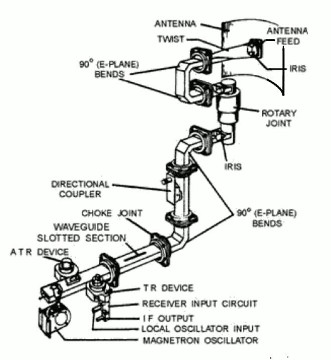
.jpg)
6. Packaging Trade-Offs: Microstrip, Drop-In, Coaxial, and Waveguide
Choosing the package is often as important as choosing the bandwidth. The package determines how the microwave circulator integrates, cools, connects, and survives.
6.1 Microstrip Wideband Circulator
Microstrip versions are attractive when low profile, low mass, and PCB-level integration are priorities. They are well suited for compact modules, phased-array subsystems, hybrid RF assemblies, and high-density front ends. Their strengths are integration efficiency and broadband potential in planar structures. Their trade-offs often include lower ultimate power handling than waveguide and stronger dependence on substrate, assembly, and thermal design.
6.2 Drop-In Wideband Circulator
Drop-in devices are widely used in compact RF modules where engineers want a packaged ferrite component that inserts into a machined housing or module base. They often strike a useful balance among size, power, ruggedness, and manufacturability. In modern radar, defense, 5G, and high-density microwave modules, the drop-in format is popular because it respects space without pretending thermal management is optional.
6.3 Coaxial Wideband Circulator
Coaxial versions are easy to integrate in connectorized systems and benches. They are common in lab setups, instrumentation, lower-frequency ranges, and many general-purpose RF chains. They can be robust, user-friendly, and straightforward to swap. Their limitation is that connectorized convenience does not automatically make them the best answer for the highest-density or highest-power integrated architectures.
6.4 Waveguide Wideband Circulator
Waveguide circulators are favored when low insertion loss and high power handling dominate the decision. They are common in radar, satcom, high-frequency links, and demanding microwave infrastructures. Dual-ridge waveguide implementations are especially relevant for wideband performance because the ridge structure can expand usable bandwidth relative to conventional rectangular solutions. The trade-off is obvious: waveguide parts are larger, more mechanically constrained, and less friendly to ultra-compact packaging.
| Package | Strengths | Limitations | Best-Fit Scenarios |
|---|---|---|---|
| Microstrip | Low profile, light weight, PCB/hybrid integration, broad planar usefulness | Power and thermal limits versus waveguide; substrate sensitivity | Compact front ends, phased arrays, integrated modules |
| Drop-in | Good compactness, rugged packaging, practical for dense modules | Requires mechanical cavity planning and thermal path attention | Radar modules, defense electronics, compact high-performance assemblies |
| Coaxial | Connectorized convenience, easy bench use, broad availability | Larger connector overhead, less elegant for deeply integrated layouts | Lab, instrumentation, general RF systems, serviceable field units |
| Waveguide | Low loss, strong power handling, excellent for demanding microwave paths | Bulky, mechanically constrained, less suitable for compact PCB systems | Radar, satcom, high-power microwave links |
There is no universally superior package. There is only the package that best serves the power, thermal, size, bandwidth, and integration logic of your system. Engineering, once again, declines to offer a fairy tale ending.
7. Supplier Landscape: Major Companies and HzBeat
The wideband RF circulator market is not a single-lane road. Suppliers differ by packaging depth, customization capability, qualification level, stock model strategy, and willingness to optimize for real-world application conditions rather than catalog theater.
7.1 Smiths Interconnect
Smiths Interconnect publicly lists broad circulator and isolator offerings across coaxial, drop-in, microstrip/SMT, stripline, and waveguide formats, with positioning toward defense, aerospace, and demanding RF/microwave applications. For buyers who prioritize long history, qualification culture, and broad portfolio depth, Smiths is an important reference point.
7.2 UIY
UIY offers a wide circulator and isolator portfolio covering coaxial, drop-in, microstrip, and waveguide families with broad frequency coverage and customization options. The company is visible across commercial and industrial RF catalog channels and is often encountered when engineers search for configurable ferrite components across many bands.
7.3 RF-Lambda
RF-Lambda maintains product lines for coaxial, drop-in, and waveguide circulators and isolators and is often considered when engineers need a broad catalog source with standard RF/microwave infrastructure coverage. It is especially visible in connectorized and catalog-oriented sourcing workflows.
7.4 MECA Electronics
MECA is a long-established supplier of RF/microwave passive components and offers circulators in commonly used frequency and connector ranges. In many procurement contexts, it appears as a practical choice for conventional connectorized RF hardware, especially where stock availability and mainstream ranges matter.
7.5 HzBeat
HzBeat’s positioning is especially relevant when the conversation moves from ordinary to awkward—that is, when customers need wideband RF circulator solutions with customization, miniaturization, and multi-package coverage rather than a one-size-fits-all part number. Public HzBeat product pages highlight microstrip, drop-in, coaxial, and waveguide solutions, including examples such as 2–40 GHz microstrip coverage, 2–6 GHz and 6–18 GHz broadband drop-in configurations, broadband coaxial options, and dual-ridge waveguide products for ultra-wideband microwave applications.
From a market-positioning standpoint, HzBeat’s strongest talking points are not vague slogans but practical engineering themes: ultra-wideband capability, compact structure, and cross-package customization. For customers who need an RF component vendor that can work with packaging realities and band-specific requirements instead of simply quoting the nearest shelf unit, that matters.
| Supplier | Visible Strength | Typical Fit |
|---|---|---|
| Smiths Interconnect | Broad portfolio across multiple package types, strong defense/aerospace positioning | Qualified, high-reliability and high-spec RF/microwave programs |
| UIY | Wide catalog and customization across many ferrite formats | Commercial, industrial, and custom multi-band sourcing |
| RF-Lambda | Catalog breadth in coaxial, drop-in, and waveguide lines | Standardized RF component procurement and engineering evaluation |
| MECA Electronics | Established RF passive vendor with practical connectorized circulator lines | Conventional RF system builds and serviceable connectorized chains |
| HzBeat | Ultra-wideband focus, miniaturization, cross-package custom support | Projects requiring broadband performance plus packaging flexibility |
8. How to Select the Right Wideband RF Circulator
A smart selection workflow starts by resisting the temptation to ask only three questions: frequency, price, and delivery. That is how projects end up writing apology emails later.
8.1 Define the True Bandwidth
State the usable frequency range, not just the nominal center. Include guard bands, drift, and future operating headroom.
8.2 Check Insertion Loss Across the Entire Band
Do not be hypnotized by a single “typical” point. Review max loss over the intended temperature range and under realistic mismatch assumptions if available.
8.3 Evaluate Isolation Honestly
Minimum isolation matters, but so does flatness. A wideband RF circulator with a charming peak and ugly edges may be the wrong part for an agile or broadband system.
8.4 Match the Package to the Platform
Choose microstrip, drop-in, coaxial, or waveguide based on integration logic, not habit. Bench convenience and deployed-system suitability are rarely the same thing.
8.5 Review Power, Temperature, and Thermal Path
Ask about average power, peak power, reverse power exposure, operating temperature, and mounting recommendations. Broadband performance is meaningful only if the heat can leave the party.
8.6 Clarify Direction and Porting
Clockwise and counterclockwise options matter. So do connectors, flange standards, footprint constraints, and grounding strategy.
8.7 Ask About Customization
If your project sits between catalog bands, unusual environmental requirements, or tight mechanical envelopes, supplier customization capability is often more valuable than a big PDF catalog.
8.8 Request Data That Looks Like Engineering
Useful vendor data includes S-parameters, mechanical drawings, temperature behavior, power notes, and ideally application guidance. If the documentation sounds too smooth, it may have been polished until the truth fell out.
9. Conclusion
A wideband RF circulator is more than a broader spec line on a datasheet. It is an enabling component for microwave systems that need flexibility, broadband routing discipline, and credible protection across more of the real operating range. Compared with a narrowband RF circulator, it usually demands more design effort, more careful matching, and more thoughtful material and packaging decisions. But in radar, satcom, EW, test and measurement, and compact multi-band RF hardware, the value is often unmistakable.
The right question is not “Is wideband better?” The right question is “Does my system benefit enough from wider operational certainty to justify the part?” If the answer is yes, then package style, ferrite design, thermal path, isolation flatness, and supplier customization become the real decision factors. That is where informed engineering separates itself from checkbox procurement.
For teams evaluating suppliers, the landscape includes established names with deep portfolios and newer or more specialized manufacturers with stronger customization agility. In that conversation, HzBeat’s value proposition is straightforward: wideband coverage, miniaturized structures, and cross-package support tailored to demanding RF and microwave applications. No fireworks. Just the kind of sentence engineers usually trust more.
10. FAQ
Q1. Is a wideband RF circulator always better than a narrowband one?
No. If your system runs in a tightly fixed band and cost or peak center-frequency performance dominates, a narrowband RF circulator may be the better choice.
Q2. Which package is best for a compact microwave module?
Usually microstrip or drop-in. Microstrip favors low-profile integration, while drop-in formats often provide a stronger balance among compactness, ruggedness, and practical power handling.
Q3. Why do waveguide circulators remain important in broadband microwave systems?
Because they can offer low insertion loss and high power handling, especially in radar and satellite communication paths where compact PCB packaging is not the top priority.
Q4. What usually limits broadband circulator performance?
Ferrite behavior, magnetic bias optimization, junction geometry, matching structure, thermal conditions, and packaging transitions all shape the final bandwidth and loss/isolation balance.
Q5. What should buyers ask suppliers before ordering?
Ask for frequency range, insertion loss and isolation across the full band, power ratings, operating temperature, package details, direction, S-parameters, mechanical drawings, and customization capability.
Q6. Can one supplier cover all four package types?
Some can. Public product portfolios from companies such as Smiths Interconnect, UIY, and HzBeat indicate support across multiple circulator structures, though depth and customization style vary.
11. References
- Smiths Interconnect. Isolators and Circulators.
- Smiths Interconnect. Microstrip Isolators and Circulators.
- UIY. RF/Microwave Products.
- UIY. Drop-in Circulator.
- UIY. Waveguide Circulator.
- RF-Lambda. Circulator (Coaxial / Drop-In).
- RF-Lambda. Waveguide Circulator/Isolator.
- MECA Electronics. RF Circulator.
- HzBeat. Typical Microstrip Circulator.
- HzBeat. Broadband Drop-In Circulator.
- HzBeat. Broadband Coaxial Circulator.
- HzBeat. Dual-Ridge Waveguide Circulator.
- Ashley, A. et al. Bandwidth Design of Ferrite-Based Circulators.
- Oskouei, H.R.D. et al. Design and Construction of Ferrite Waveguide Circulator.
- Tang, T. et al. Design of X-Band Circulator and Isolator for High-Peak-Power Applications.
Recommended Products

.jpg)


Keith Wong
Marketing Director, Chengdu Hertz Electronic Technology Co., Ltd. (Hzbeat)
Keith has over 18 years in the RF components industry, focusing on the intersection of technology, healthcare applications, and global market trends.