RF Circulators vs. RF Isolators in Radar & Comms
A practical and thorough guide to circulators and isolators: principles, key parameters (IL/Isolation/RL/Bandwidth/Power), packaging (waveguide/coax vs microstrip/stripline), radar & communication use cases, selection checklist, and HzBeat product examples with figure-by-figure explanations.
1. Introduction
The comparison between an RF circulator and an RF isolator is one of the most common questions in practical RF and microwave engineering, yet it is also one of the easiest topics to oversimplify. Many articles stop at “a circulator has three ports, an isolator has two,” but that level of explanation is not enough for real design work. The real engineering issue is not only the number of ports. The real issue is what the RF chain needs the component to do.
In a radar system, an RF circulator may be the device that lets the transmitter and receiver share one antenna path while maintaining directional control of signal flow. In the same radar system, an RF isolator may be placed near the low-noise receive chain or other vulnerable stages to absorb unwanted reverse energy and improve stability. In a communication system, the RF isolator is often the preferred tool for protecting a power amplifier from reflected power caused by antenna mismatch, while the RF circulator becomes valuable when the system architecture needs duplexing, routing, or controlled non-reciprocal flow among ports.
That is why the title of this article matters. RF Circulators vs. RF Isolators in Radar & Comms is not just a general component comparison. It is a system-level question. To answer it properly, the article must connect the component physics to two real application worlds: radar systems and communication systems. Those are related worlds, but not identical ones. Radar often begins with questions of duplexing, antenna sharing, echo sensitivity, and receiver survivability. Communication often begins with questions of power amplifier stability, mismatch tolerance, spectral cleanliness, and reliable field operation.
This article therefore does six things in one complete flow. First, it defines what an RF circulator and an RF isolator are in engineering terms. Second, it explains the underlying non-reciprocal operating principle. Third, it shows why the two devices are related but not interchangeable. Fourth, it discusses in detail how they are used in radar systems. Fifth, it explains how they are used in communication systems. Sixth, it closes with specification reading, packaging choices, and a practical selection checklist so that the discussion does not stay trapped in theory.
2. One-minute Overview
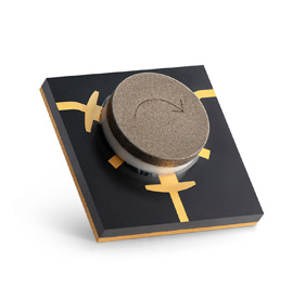
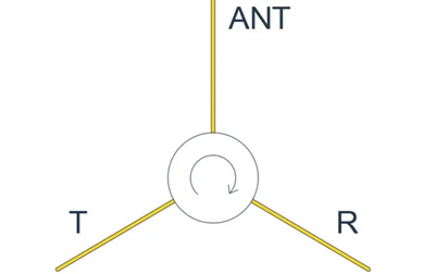
An RF circulator is typically a three-port ferrite device in which power entering one port is guided to the next port in a defined direction. In a clockwise version, power might flow 1→2, 2→3, and 3→1. In a counterclockwise version, the sequence is reversed. The key point is that transmission is intentionally non-reciprocal. This makes the RF circulator useful for routing transmit and receive paths, sharing a single antenna, or creating directional flow inside a microwave network.
An RF isolator is usually implemented by taking a circulator-like non-reciprocal junction and terminating one port with a matched load. The result is a device that behaves like a two-port component: forward energy passes through, while reverse energy is diverted into the load and dissipated as heat. That makes the RF isolator useful for protecting a power amplifier, an oscillator, an LNA, or any other sensitive RF stage from reflected power and poor load conditions.
If you want the shortest possible engineering mnemonic, it is this: an RF circulator routes, an RF isolator protects. But the rest of the article matters because in real radar systems and real communication systems, routing and protection are often intertwined. Designers must know when a circulator alone is enough, when an isolator is needed, and when both should appear in the same chain.
3. RF Circulator vs RF Isolator: The Core Difference
At the component level, the relationship between an RF circulator and an RF isolator is close enough that people often treat them as interchangeable in conversation. At the system level, that assumption can cause design mistakes. The core difference is that the RF circulator is primarily a directional routing device, while the RF isolator is primarily a reverse-power management and protection device.
| Comparison Item | RF Circulator | RF Isolator |
|---|---|---|
| Primary function | Directional signal routing among ports | Forward transmission and reverse-power absorption |
| Typical configuration | Three-port non-reciprocal device | Two-port behavior, often from a circulator with one terminated port |
| Main system role | Duplexing, antenna sharing, controlled routing | Protection, mismatch tolerance, stability improvement |
| Reverse energy | Sent to a different port | Sent into a matched load and dissipated as heat |
| Typical radar use | Shared TX/RX antenna path | Receiver-side protection or auxiliary-stage isolation |
| Typical communication use | Routing, duplexing, specialized non-reciprocal flow | PA protection and load stabilization |
This is why a circulator cannot fully replace an isolator in a chain where absorbed reverse energy is required, and an isolator cannot replace a circulator in a chain that fundamentally needs multi-port directional routing. In short, the two components are cousins, not twins.
4. How an RF Circulator and an RF Isolator Work
4.1 How an RF Circulator Works
An RF circulator operates by using ferrite material under magnetic bias to create non-reciprocal signal behavior. In ordinary passive reciprocal networks, if a signal can move efficiently from A to B, it can usually move with similar behavior from B to A. A circulator is different. Because of the ferrite physics and magnetic bias conditions, the device encourages energy to travel preferentially from one port to the next in a loop-like sequence.
This non-reciprocal behavior is why the RF circulator is so useful in radar systems and other front ends that need one antenna to serve more than one function. In a simple radar duplexing scenario, transmitter energy enters the circulator and exits toward the antenna. Reflected target echoes returning from the antenna then enter that antenna-facing port and are directed toward the receiver path instead of back into the transmitter. The result is elegant: one passive ferrite component enables controlled signal flow between transmitter, antenna, and receiver.
However, the RF circulator is not magic. Its real performance depends on frequency, magnetic bias, ferrite properties, impedance matching, junction topology, temperature behavior, packaging consistency, and mechanical assembly. A circulator that looks excellent on a datasheet but is poorly integrated can lose isolation, drift in return loss, or introduce more insertion loss than expected.
4.2 How an RF Isolator Works
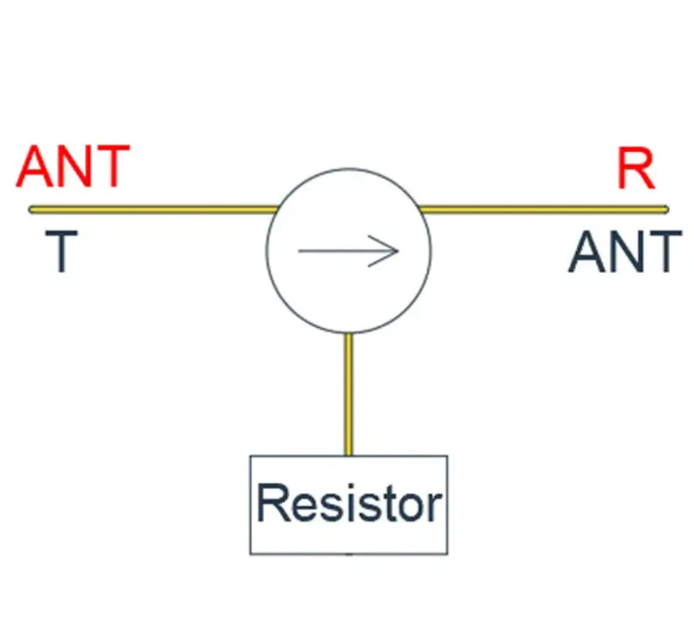
An RF isolator is based on the same non-reciprocal physics, but its practical role is different. By terminating the third port of the non-reciprocal junction in a matched load, the device behaves as a one-way component. Forward energy passes through the desired path. Reverse energy is not simply reflected backward; it is sent to the termination and dissipated.
That simple change has deep system consequences. In a communication transmitter chain, it means the power amplifier sees a more controlled environment even when the antenna match becomes poor. In a radar receive path, it means a sensitive stage can be shielded from energy that should not be allowed to return into the circuit. In any RF system where reverse energy leads to gain ripple, instability, oscillation risk, or performance drift, the RF isolator provides a much more controlled answer than “hoping the load behaves.”
The important caution is thermal. An isolator does not make reverse power disappear. It converts that reverse energy into heat in the termination. So the RF isolator is not only an RF component. It is also a thermal design component, and the load must be treated accordingly.
5. RF Circulators and RF Isolators in Radar Systems
If the article title mentions radar, then the radar section must do more than name-drop the word. Radar is one of the clearest places to see why an RF circulator and an RF isolator are different.
5.1 Shared-Antenna Operation and Duplexing
Many radar systems use a common antenna aperture for transmission and reception. That makes the circulator or another duplexing function essential. A duplexer is the network that allows transmitter and receiver paths to share one antenna. In lower-power or certain practical radar architectures, the duplexer can be implemented with a circulator. That is one reason the RF circulator is so closely associated with radar front ends.
In this role, the RF circulator is not just a passive accessory. It helps define the signal path architecture. It supports single-antenna operation, reduces hardware count, reduces interconnect complexity, and preserves a compact front-end layout. Those benefits matter in conventional radar, compact sensing radar, FMCW radar, and many phased-array subassemblies.
5.2 Receiver Protection and Sensitivity
Radar systems often transmit strong signals and then attempt to detect extremely weak return echoes. That means the receiver chain—especially the earliest LNA stages—must be protected from overload, leakage, and poor load behavior. This is where the RF isolator becomes relevant.
Even if the main TX/RX routing job is handled by an RF circulator, an RF isolator may still be needed near the low-noise receive chain or other sensitive stages. The reason is practical: reflected power, poor antenna behavior at extreme scan angles, switching transients, and front-end mismatch conditions can all threaten the stability or safety of the receive chain. By absorbing reverse energy instead of allowing it to bounce around the network, the RF isolator helps preserve receiver integrity.
5.3 Phased-Array Radar and T/R Modules
In phased-array radar, the conversation becomes even more interesting. A phased-array front end may involve a very large number of transmit/receive channels, each with tight size, loss, thermal, and repeatability constraints. In these systems, the value of a compact RF circulator or RF isolator is not just the individual device function; it is the cumulative impact across many channels. A small insertion loss penalty repeated across numerous channels can matter. A mismatch problem repeated across many power amplifiers can matter even more.
Microwaves101’s discussion of T/R modules is useful here because it points out that a circulator enables antenna sharing, while an isolator can be used to shield a power amplifier from poor impedance behavior and to prevent mismatch-related load-pull effects from degrading radar performance. In some designs, these functions may be integrated into a four-port assembly or solved through related protection strategies, but the logic remains the same: the circulator addresses routing, while the isolator addresses stability and protection.
5.4 Pulse Radar, FMCW Radar, and Real Integration Trade-Offs
In pulse radar, the contrast between strong transmit power and weak receive echoes can be extreme, which makes both routing and protection crucial. In FMCW radar, size and integration can become especially important because front-end packaging and low-loss signal flow directly influence sensitivity and repeatability. In active phased-array systems, the number of channels and the sensitivity to thermal and mechanical variation push the designer toward components that not only meet nominal performance but also maintain repeatability over temperature, vibration, rework, and production spread.
| Radar Design Need | Component More Closely Associated | Why |
|---|---|---|
| Shared TX/RX antenna path | RF Circulator | Provides directional routing between transmitter, antenna, and receiver |
| Receiver-side protection | RF Isolator | Absorbs reverse energy that could disturb or damage sensitive stages |
| Compact duplexing function | RF Circulator | Supports one-antenna architectures with reduced path complexity |
| Mitigation of mismatch-related instability | RF Isolator | Creates a more controlled impedance environment for vulnerable stages |
So in radar systems, the article title becomes highly literal: RF circulators vs RF isolators is not a theoretical “which is better” debate. It is a question of which function the radar chain needs at a given location.
6. RF Circulators and RF Isolators in Communication Systems
The communication side of the title deserves equal weight. A good article on RF circulators vs RF isolators in communication systems must explain why the communication engineer often starts from a different pain point than the radar engineer.
6.1 Power Amplifier Protection
In many communication systems, the most immediate reason to deploy an RF isolator is to protect the power amplifier. Real antennas are not perfect loads. Field conditions change. Installations vary. Connectors loosen. Nearby structures change the effective match. When the load seen by the PA moves away from its intended impedance, reflected power can return into the chain. That reverse energy can affect amplifier efficiency, output consistency, linearity, thermal behavior, and long-term reliability.
This is why the RF isolator is common in base-station hardware, microwave radio links, satellite terminals, and other communication transmit chains. By absorbing reverse energy instead of sending it back into the active device, the RF isolator gives the PA a more stable environment. In many systems, that translates into fewer surprises in the field.
6.2 Communication Systems Still Need Circulators
It would be a mistake, however, to conclude that communication systems are “about isolators only.” A communication front end may still need an RF circulator when directional signal routing or non-reciprocal path management is required. This can occur in shared-path architectures, duplexing arrangements, specialized microwave links, certain satellite communication subsystems, and other assemblies where simply protecting the PA is not enough. In those cases, the RF circulator provides a controlled way to move energy among multiple ports.
6.3 Satellite Communication and Ground Systems
Satellite communication is a particularly useful bridge between the communication and radar worlds. Official ESA and NASA materials on satellite communications and ground stations remind us that large communication systems often depend on high-reliability RF chains, large antennas, and carefully managed uplink/downlink paths. In such systems, components that preserve low loss, provide stable routing, and improve mismatch tolerance remain central even if they are not always visible from the outside.
NASA’s Deep Space Network is a useful communication example because it is, fundamentally, a giant radio-frequency telecommunication system based on large antennas that transmit, receive, and track extremely weak signals over enormous distances. That context highlights why components such as an RF circulator or RF isolator matter so much in communication engineering: when the link budget is demanding and the signals are precious, uncontrolled reflections and poor front-end behavior become very expensive problems.
6.4 Communication Metrics: Stability, Linearity, Reliability
Communication engineers often frame the circulator/isolator choice around slightly different language than radar engineers. Instead of talking first about duplexing or receiver overload, they may talk about amplifier stability, VSWR tolerance, spectral cleanliness, and field reliability. Those are not different physics; they are different failure modes inside a different system objective.
If the chain’s main concern is preventing reflected power from punishing the PA, the RF isolator is usually the cleaner answer. If the chain needs non-reciprocal routing among ports, the RF circulator becomes the more natural device. Once again, the two are related, but they do not do the same job.
| Communication Design Need | Component More Closely Associated | Why |
|---|---|---|
| PA protection from reflected power | RF Isolator | Absorbs reverse energy and reduces load-pull sensitivity |
| Directional signal routing | RF Circulator | Creates controlled multi-port non-reciprocal flow |
| Improved mismatch tolerance | RF Isolator | Stabilizes the RF chain when the antenna or load is imperfect |
| Specialized duplexing or shared-path control | RF Circulator | Supports architectures needing routing rather than only protection |
7. Key Specifications: Insertion Loss, Isolation, VSWR, Bandwidth, Power
Whether the device is an RF circulator or an RF isolator, the datasheet numbers only matter if they are interpreted in context. A component is not selected on one heroic specification alone. It is selected on how the specification stack interacts with the actual radar or communication architecture.
7.1 Insertion Loss
Insertion loss matters because every fraction of a decibel in the wrong place hurts system margin. In a radar receiver path, extra insertion loss directly degrades sensitivity. In a communication transmitter chain, extra insertion loss reduces available power to the antenna and raises effective inefficiency. For that reason, insertion loss is not a cosmetic number. It is a system-budget number.
7.2 Isolation
Isolation is central because it expresses how well undesired coupling is suppressed. In a circulator, isolation is tied to how effectively the non-reciprocal routing is maintained. In an isolator, isolation contributes to how well reverse energy is kept out of the protected path. Microwaves101 also notes a useful engineering rule of thumb: circulator isolation is closely tied to return loss behavior, which is one reason that matching and termination quality matter so much.
7.3 VSWR and Return Loss
Return loss and VSWR matter because they indicate how well the component is matched to the surrounding network. A mismatch at the wrong interface can create ripple, worsen apparent isolation, or degrade stage-to-stage behavior. In communication systems, poor matching can aggravate PA stress. In radar systems, it can quietly undermine the clean path you thought your architecture would have.
7.4 Bandwidth
Bandwidth determines whether the device remains useful across the actual operating band. A broader band may simplify a bill of materials or support multi-standard communication use, but wider bandwidth often comes with trade-offs in insertion loss, size, or isolation. Designers should treat bandwidth as a system choice, not a bragging number.
7.5 Power Handling and Thermal Reality
Power handling is especially important in radar transmit chains and communication PA outputs. But power handling should never be read without thermal context. Peak power, average power, duty cycle, heat sinking, and reverse-power conditions must all be considered together. For an RF isolator in particular, the termination load must survive what the system can send into it under worst-case mismatch conditions.
8. Packaging and Integration: Waveguide, Coaxial, Microstrip, Stripline
Not all RF circulators and RF isolators look alike because not all systems ask the same thing of them. The package format is part of the engineering decision.
| Form | Main Advantages | Main Cautions | Typical Fit |
|---|---|---|---|
| Waveguide | Excellent high-power handling, strong field control, robust in severe RF environments | Bulky, heavier, higher mechanical complexity | High-power radar and demanding microwave infrastructure |
| Coaxial | Mature, connector-friendly, reliable in medium/high-power paths | Larger than planar approaches, less ideal for dense PCB integration | Communication equipment, test benches, legacy assemblies |
| Microstrip | Compact, light, PCB-compatible, strong integration efficiency | More sensitive to assembly, stress, and thermal path quality | Phased-array modules, compact radar, SATCOM, dense RF boards |
| Stripline | Good shielding potential and multilayer compatibility | Requires disciplined stack-up and manufacturing control | Layered embedded microwave modules |
This package choice often reflects the radar or communication platform itself. A harsh high-power radar platform may lean toward waveguide or a robust coaxial form. A compact 5G, SATCOM, or phased-array module may lean toward microstrip because board-level integration and reduced size are decisive. But smaller is not automatically better. Miniaturization usually makes thermal, mechanical, and consistency discipline more important, not less.
9. Selection and Procurement Checklist
- Define the actual system problem. Is the chain primarily asking for routing, protection, or both?
- Confirm the true operating band. Do not select only by nominal center frequency; include usable bandwidth and edge behavior.
- Check insertion loss where it hurts most. In radar receive paths and communication transmit paths, small losses matter.
- Evaluate isolation with realistic matching conditions. Isolation is only as good as the practical network around it.
- Review power handling together with duty cycle and thermal path. Especially for the RF isolator load, this is non-negotiable.
- Match package format to platform needs. High power, compactness, reworkability, and production repeatability all matter.
- Ask for consistency, not just headline specs. Lot-to-lot behavior and temperature performance matter in real deployments.
10. HzBeat Product Relevance
| Product Direction | Application Value | Typical Scenarios |
|---|---|---|
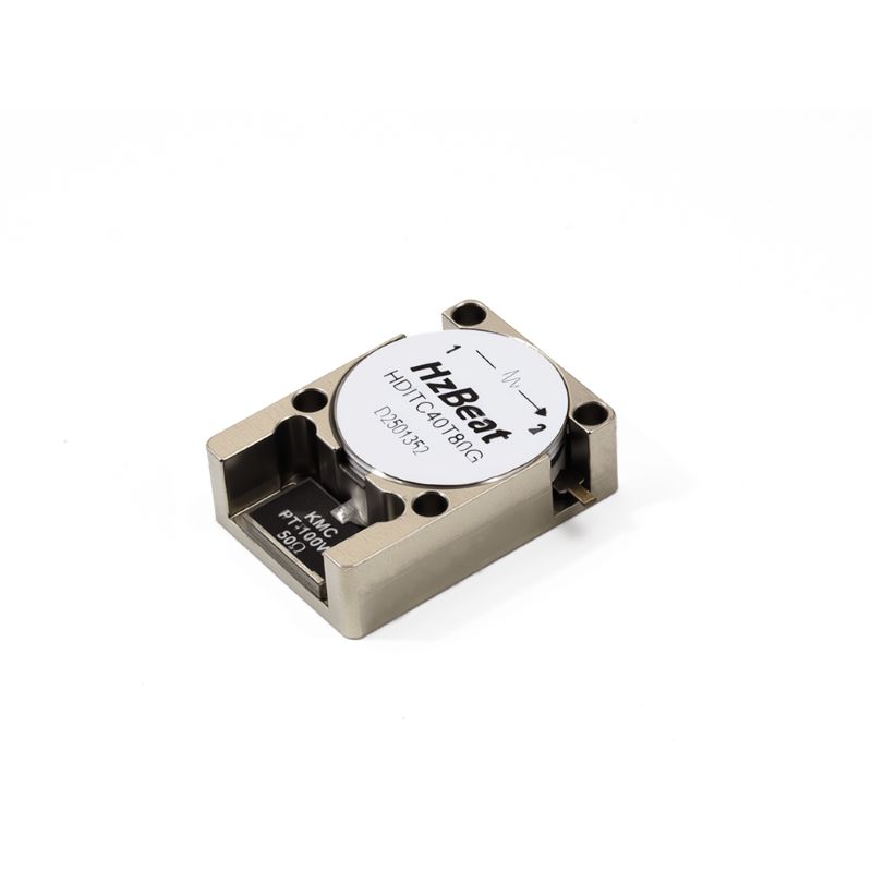
| Typical Microstrip Circulator | Suitable for directional signal routing and transmit/receive path management in compact RF front ends. | Radar front ends, wireless communication systems, integrated RF modules |
| Broadband Variants | Provide wider usable frequency coverage and better architecture flexibility in multi-band or broadband systems. | Wideband radar platforms, multi-standard communication equipment, SATCOM subsystems |
| Miniaturized Variants | Support high-density integration and help reduce front-end size without changing the basic non-reciprocal function. | Phased-array modules, compact communication boards, space-constrained microwave assemblies |
11. FAQ
Can an RF circulator replace an RF isolator?
Not completely. An RF circulator can route reverse energy to another port, but an RF isolator is designed to absorb reverse energy in a matched load. If the system requirement is true reverse-power protection, the RF isolator is usually the correct choice.
Why is an RF circulator so common in radar systems?
Because radar systems often need one antenna to handle both transmit and receive paths. The RF circulator provides directional routing that makes this practical without requiring separate antennas in many architectures.
Why is an RF isolator so common after a power amplifier?
Because the RF isolator protects the PA from reflected power caused by load mismatch, antenna behavior, or other real installation problems. This improves stability and reliability.
Can a radar system use both an RF circulator and an RF isolator?
Yes. The RF circulator may provide the duplexing or routing function, while the RF isolator may protect a sensitive stage or improve the impedance environment for a vulnerable part of the chain.
Which matters more: insertion loss or isolation?
Both matter, but in different ways. Insertion loss hurts efficiency and sensitivity. Isolation protects signal integrity and stability. The correct priority depends on where the device sits in the radar or communication system.
12. Conclusion
RF circulators and RF isolators are both essential non-reciprocal microwave components, but they are not different labels for the same function. An RF circulator is fundamentally about directional routing. An RF isolator is fundamentally about reverse-power absorption and protection.
That distinction becomes most meaningful when viewed through the lens of the article title itself. In radar systems, the RF circulator is often associated with shared-antenna TX/RX routing, while the RF isolator is associated with receiver-side protection, mismatch control, or other stability-driven roles. In communication systems, the RF isolator is frequently deployed after the power amplifier to reduce the consequences of reflected power, while the RF circulator appears where directional path control or specialized duplexing is needed.
So the practical answer to “RF circulators vs. RF isolators in radar & comms” is not “one is better.” The real answer is more mature: they solve different problems. Robust RF systems are built by assigning the right function to the right ferrite device, then validating that choice against real loss, isolation, bandwidth, power, temperature, packaging, and production constraints.
13. References
- Pozar, David M. Microwave Engineering, Wiley.
- Collin, Robert E. Foundations for Microwave Engineering, McGraw-Hill.
- Microwaves101 — Circulators.
- Microwaves101 — Isolators.
- Microwaves101 — Duplexers.
- Microwaves101 — Transmit/Receive Modules.
- Microwaves101 — Dual Junction Circulators.
- Pasternack datasheet examples for RF circulators showing transceiver/antenna routing and the use of matched termination to create isolator behavior.
- NASA — What is the Deep Space Network?
- USGS — Deep Space Network communications antenna at Goldstone.
- ESA — Satellite communications and ground-station resources.
- HzBeat — Typical Microstrip Circulator and related RF circulator / RF isolator technical resources.
Recommended Products

.jpg)

Keith Wong
Marketing Director, Chengdu Hertz Electronic Technology Co., Ltd. (Hzbeat)
Keith has over 18 years in the RF components industry, focusing on the intersection of technology, healthcare applications, and global market trends.