Where Does Reflected Energy Go in High-Power Radar? Understanding the Circulator Protection Path
Follow antenna reflections through the circulator, receiver protector, and matched load—and understand where RF energy finally becomes heat.
 Updated on: Sep 10, 2026
 Author:
A high-power radar may launch kilowatts—or megawatts of peak RF power—through the same antenna that later listens for extremely weak echoes. When some of that transmitted wave returns toward the source, the energy does not disappear. Its destination is set by impedance, nonreciprocal routing, and the protection devices connected to the circulator.
The short answer
In an isolator, the third port of a circulator is deliberately terminated in a matched load. That load is the element intended to turn reverse RF power into heat. In a radar duplexer, however, the third port is normally part of the receive path. A receiver-protection network must therefore handle the strong transient that can precede the useful echo.
The engineering question is not simply “How much isolation does the circulator provide?” It is “What power, pulse energy, voltage, and temperature appear at every node for every allowed mismatch and fault?”
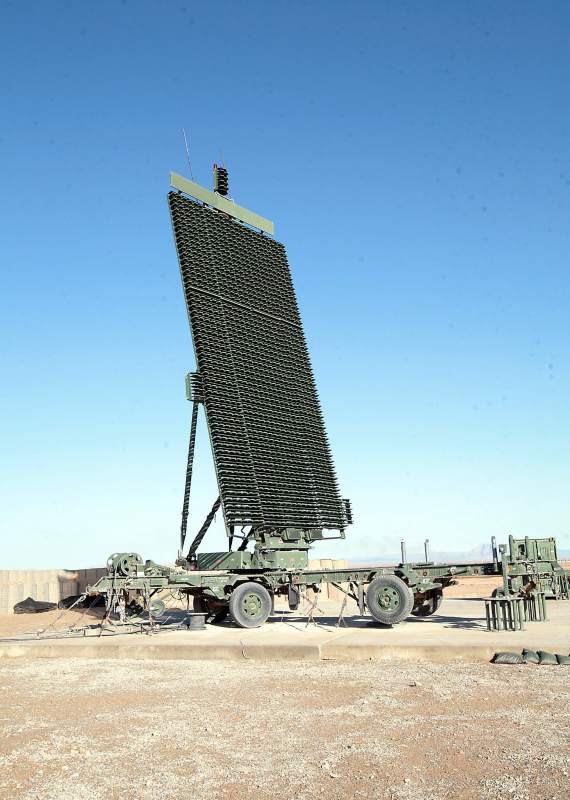
Do not confuse three different energies
1. The intended transmitted field
Most accepted power is radiated by the antenna. It propagates through space; only a very small portion intercepted and scattered by a target returns to the radar as a useful echo.
2. The antenna/feed mismatch reflection
Imperfect impedance match at the antenna, radome, rotary joint, feed, or a fault sends part of the incident wave back down the transmission line almost immediately.
3. Direct transmit-to-receive leakage
A real circulator has finite reverse isolation. Some transmitter power therefore reaches the receive port even before antenna reflection, and parasitic coupling can add further leakage.
The second and third components are usually the dominant front-end protection problem during transmission. The useful target echo arrives later and is normally many orders of magnitude weaker. Calling all three “reflected energy” hides the timing and the hardware path that matter most.
How a three-port circulator routes the waves
A ferrite circulator is a passive, nonreciprocal microwave network. A static magnetic bias makes its transmission direction-dependent. With one common port convention, the preferred sequence is 1 → 2, 2 → 3, and 3 → 1. Renumbering or reversing the magnetic bias reverses the apparent rotation, so the arrows on the actual component—not a generic drawing—govern the installation.
For an ideal circulator, each port is matched, forward insertion loss is zero, and reverse isolation is infinite. Real hardware departs from all three conditions. Its insertion loss dissipates a small share of forward power; finite isolation leaks power into the nominally isolated port; and finite port return loss creates additional reflections. The ferrite junction must also remain below its peak-power, average-power, temperature, and magnetic-bias limits.
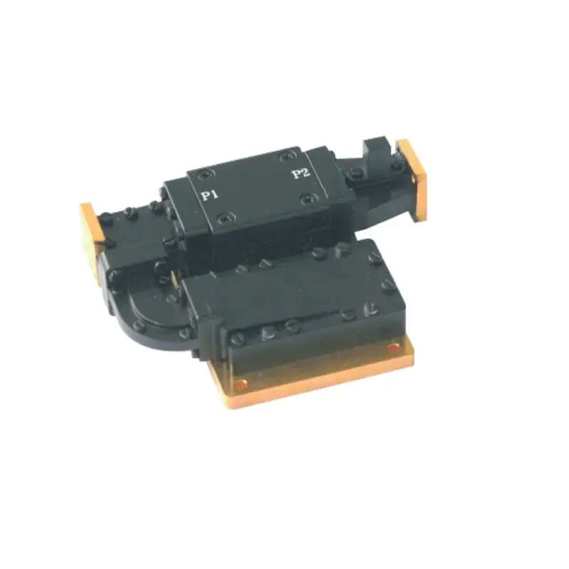
The protection path: routing is only the first layer
1. The circulator separates directions
During the transmit pulse, the circulator preferentially couples the transmitter to the antenna. A wave returning from the antenna enters the antenna port in the reverse physical direction but follows the circulator’s next permitted route—normally toward the receiver port, not back to the power amplifier.
2. A receiver protector clamps, switches, reflects, or absorbs
The receive branch may include a gas-discharge TR device, a high-power PIN-diode limiter, a lower-power limiter, an absorptive protection switch, filters, or combinations of them. These elements are cascaded because no single number describes protection. Important quantities include turn-on threshold, spike leakage energy, flat leakage power, recovery time, pulse width, duty cycle, and survivable peak and average input power.
3. Residual power reaches the LNA
The LNA must survive whatever remains after direct circulator leakage, antenna reflection, protector insertion loss, turn-on delay, and protector leakage are combined. Phase matters: multiple leakage paths are coherent at RF and can add or cancel. Using only scalar isolation values may therefore underestimate a worst-case voltage or current peak.
4. Reflected power may circulate again
A reflective limiter behaves approximately like a changing mismatch when it turns on. Power sent back toward the circulator can be routed onward—often toward the transmitter port—and may make additional trips if other ports are poorly matched. Designers sometimes add another circulator, an isolator, or an absorptive switch so that this rejected power has a defined high-power load rather than an uncontrolled standing-wave path.
Follow the power with three simple quantities
For a real, positive reference impedance Z0, evaluated at one reference plane:
A perfect match has Γ = 0 and no reflected wave. An ideal open or short has |Γ| = 1 and reflects all incident power, although with different phase. Return loss is better when its positive dB value is larger: 20 dB return loss means 1% reflected power; 10 dB means 10%; 3 dB means approximately 50%.
Worked example: why “only 10% reflected” can still be severe
Assume a radar produces a 1 MW peak pulse at 1% duty cycle. Ignore path loss for a first-order estimate and let the antenna return loss degrade to 10 dB.
Reflected: 100 kW peak, 1 kW average
That is the power launched back toward the circulator before accounting for its insertion loss or the receiver protector. A component may survive the peak but overheat on average, or tolerate the average but break down at the peak electric field. Both ratings—and pulse energy—must be checked.
| Return loss | |Γ| | Reflected power | At 1 MW peak |
|---|---|---|---|
| 20 dB | 0.10 | 1% | 10 kW |
| 10 dB | 0.316 | 10% | 100 kW |
| 6 dB | 0.501 | 25.1% | 251 kW |
| 3 dB | 0.708 | 50.1% | 501 kW |
| 0 dB | 1.00 | 100% | 1 MW |
For a realistic budget, apply complex S-parameters rather than subtracting catalog dB values blindly. Include the circulator’s frequency- and temperature-dependent S21, S32, S31, all relevant reflection coefficients, electrical lengths, and nonlinear limiter state. Then verify the model with calibrated high-power measurements and safe fault cases.
What can still go wrong?
The load is not truly matched at the operating frequency
A resistor marked 50 Ω is not automatically a broadband microwave match. Package size, pads, heat spreaders, and transitions add reactance. A high-power termination can reflect enough energy to degrade the intended protection path.
Isolation is treated as a shield rather than a finite ratio
At megawatt peak levels, even tens of decibels of isolation may leave substantial instantaneous leakage. Isolation also varies across bandwidth, temperature, drive level, magnetic field, and manufacturing tolerance.
Peak power is checked but pulse energy and average power are ignored
Breakdown, multipaction, arcing, ferrite nonlinearity, and semiconductor voltage stress are linked to peak conditions. Heating of ferrite, waveguide loss, terminations, and limiter junctions depends strongly on duty cycle, pulse width, cooling, and thermal time constants.
The protector recovers too slowly
A limiter that survives the transmit pulse can still desensitize the receiver if it remains lossy during the earliest desired echo. Protection and minimum detectable range are therefore coupled through recovery time.
A fault changes the entire route
An open feed, arc, iced radome, damaged rotary joint, disconnected load, or mistuned antenna can move the reflection coefficient close to unity. Protection must be designed for credible faults, not just nominal antenna VSWR.
An engineer’s checklist for tracing the energy
- Confirm the actual circulator rotation and port assignment from the manufacturer’s drawing.
- Separate direct TX→RX leakage from antenna-return power and from genuine target echoes.
- Calculate Γ, return loss, VSWR, peak reflected power, pulse energy, and average reflected power.
- Use complex, large-signal data where paths are coherent or limiters are nonlinear.
- Rate the circulator, limiter, switches, transitions, and load for frequency, pulse width, duty cycle, temperature, altitude, and cooling.
- Account for limiter spike leakage, flat leakage, recovery time, and the LNA’s actual survival limit.
- Check whether rejected power is absorbed or merely reflected into another path.
- Monitor forward and reflected power and define a fast transmitter foldback or shutdown threshold.
- Verify nominal and fault cases with calibrated directional measurements and appropriate high-power safety controls.
FAQ
Does a circulator absorb the reflected power?
A circulator primarily routes it to the next port. A matched termination connected to that port can absorb the routed power and dissipate it as heat. A real circulator also dissipates some power through its internal losses.
Does the third port always connect to a dummy load?
No. In a three-port isolator arrangement it connects to a load; in a shared-antenna radar duplexer it usually connects to the receiver-protection branch. The complete circuit determines where the energy goes.
Can a circulator alone protect the receiver?
Finite transmitter leakage and antenna mismatch reflections can expose the receive branch to substantial power. Receiver protection must be selected for that exposure, including transient leakage and recovery time.
Why do peak and average power both matter?
Peak conditions affect breakdown and instantaneous device stress. Average power affects sustained heating. Pulse duration and energy also matter, so a single wattage rating cannot describe every waveform.
References
- IEEE Technology Navigator — “Circulators”. Overview of nonreciprocal routing, radar duplexer use, and isolators.
- Analog Devices — “RF Demystified: Understanding Wave Reflections”. Reflection coefficient, return loss, and power transfer.
- Analog Devices AN-2558 — “RF Switch Performance with Arbitrary Loads”. LNA protection, termination mismatch, phase, and leakage uncertainty.
- Analog Devices — “Log Amps and Directional Couplers Enable VSWR Detection”. High-VSWR damage risk and transmitter protection.
- Keysight — Circulator model documentation. Practical insertion-loss and isolation parameters.
- Keysight — “Reflection Measurements”. S-parameter reflection definitions and open/short behavior.
- IEEE IEDM — “A High Power X-band Receiver Protector”. Peak/average limiter handling, leakage, and recovery metrics.
- Microwave Journal — “Receiver Protection in S-Band Radars”. Cascaded high- and low-power limiter architecture.
- NASA TechPort — Hybrid circulator project. Ferrite nonreciprocity and radar applications.
- Skyworks — “Broadband Isolator for Interstage Applications”. Example of separate forward- and reverse-power ratings.
Recommended Products
.jpg)
 Article Tags
Keith Wong
Marketing Director, Chengdu Hertz Electronic Technology Co., Ltd. (Hzbeat)
Keith has over 18 years in the RF components industry, focusing on the intersection of technology, healthcare applications, and global market trends.