SMT RF Circulator Reflow Soldering: 10 Key Guidelines
Learn SMT RF circulator reflow soldering guidelines for profiling, PCB pads, solder paste, void control, inspection, reliability, and RF testing.
 Updated on: Aug 18, 2026
 Author:
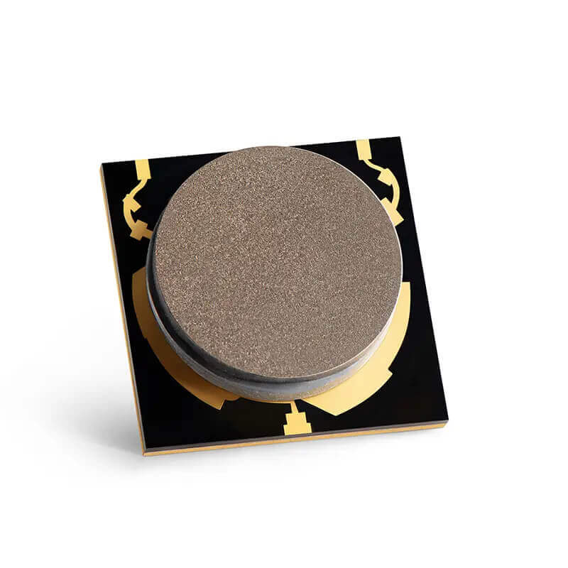
As RF front ends become smaller and more highly integrated, surface-mount circulators help reduce assembly size and support repeatable automated production. The challenge is that a ferrite circulator combines a magnetic circuit, RF conductors, grounding interfaces, and a metal package with substantially more thermal mass than many nearby passive components.
A successful SMT circulator reflow soldering process must create mechanically sound, low-impedance solder joints while protecting the component from excessive thermal or mechanical stress. That balance is why profile development, footprint control, and post-assembly RF verification deserve more attention than they would for an ordinary chip resistor.
The oven setpoint alone does not define a safe process. The decisive values are the temperatures and durations measured at the actual circulator terminals and package.

Why SMT Circulator Assembly Needs Special Control
An SMT RF circulator combines ferrite material, a magnetic bias structure, conductors, matching features, and a metal housing in a compact package. Excessive temperature or time at temperature can affect internal interfaces and may shift insertion loss, isolation, return loss, or center frequency. At the same time, the package may heat more slowly than nearby chip components because of its greater thermal mass.
The goal is therefore not simply to melt the solder. A robust process must form repeatable electrical and mechanical joints while keeping the component inside its approved thermal envelope.
Why an RF Circulator Is Different from an Ordinary SMT Passive
A resistor or capacitor is usually evaluated mainly for solderability, package integrity, and electrical value after assembly. An RF circulator has a more complex relationship with its mounting environment. Port transitions, local ground inductance, ferrite bias conditions, package stand-off, and the symmetry of the three signal paths can all influence measured microwave behavior. A joint may look acceptable under magnification while the assembled RF path still shows added insertion loss or degraded return loss.
The metal cover and internal magnetic structure also give the RF circulator a different thermal response from small surrounding components. During ramp and soak, the PCB pads may approach the target temperature before the body of the component has equalized. During cooling, the package and PCB can contract at different rates. The approved process should therefore control both the maximum exposure and the temperature difference across the local assembly.
These effects do not mean that an SMT RF circulator is difficult to manufacture. They mean that the process window must be developed with the actual component and board instead of assumed from a generic SMT recipe. Once the footprint, stencil, placement rotation, oven profile, and inspection criteria are qualified, the same controls can support repeatable automated production.
1. Develop the Reflow Profile Around the Actual Assembly
Start with the circulator datasheet and the solder-paste supplier's guidance. Then instrument a representative production board with thermocouples located as close as practical to the circulator terminals and critical ground pad. Oven air temperature is not a substitute for measured component temperature. IPC-7530B provides industry guidance for temperature profiling, while package-assembly guidance from NXP and Analog Devices likewise emphasizes measurements on the actual assembly.
| Profile stage | What to control | Main risk |
|---|---|---|
| Ramp and preheat | Heating rate and board temperature uniformity | Thermal shock, paste slump, or an excessive temperature gradient |
| Soak | Flux activation and temperature equalization | Premature flux exhaustion or uneven heating |
| Reflow | Time above liquidus and peak component temperature | Incomplete wetting or excessive thermal exposure |
| Cooling | Controlled solidification and handling delay | Disturbed joints, excess intermetallic growth, or mechanical stress |
Do not publish or apply one universal peak-temperature number for every SMT circulator. Package construction and approved limits vary by part number. If the solder paste requires conditions outside the component rating, change the materials or process rather than exceeding the rating.
How to Validate the Profile Before Volume Production
Use a fully populated production-representative PCB rather than a bare coupon. Copper density, ground planes, nearby shields, connectors, large inductors, and heat-spreading structures can change the heating rate around the RF circulator. Attach thermocouples securely at a signal terminal, the ground or thermal interface where accessible, and a nearby reference component. Poor thermocouple attachment can create misleading readings, so the attachment method should be documented with the profile.
Record the complete time-temperature curve, not only the peak value. Review ramp rate, soak behavior, time above the alloy liquidus, peak package temperature, and cooling rate against both the solder-paste specification and the RF circulator limit. The colder joint must receive enough thermal energy for wetting, while the hottest measured point must remain inside the component rating. If the temperature spread is excessive, conveyor speed, zone settings, board orientation, or local copper balance may need adjustment.
Repeat the measurement after meaningful changes to the PCB stack-up, panelization, component population, solder alloy, stencil, oven loading, or carrier fixture. A previously approved recipe is evidence for one assembly configuration; it is not automatically valid for a substantially different thermal load.
2. Use the Recommended PCB Land Pattern
Signal pads, ground pads, solder-mask openings, and via placement all influence solder-joint integrity and RF performance. Follow the manufacturer's footprint drawing whenever one is available. A casual footprint change can alter grounding inductance, impedance transitions, and heat flow during reflow. IPC-7352 provides general land-pattern guidance, but it does not replace the approved footprint for the specific circulator.
Thermal or grounding vias beneath a center pad may be useful, but open vias can wick solder away from the joint. Filled, capped, tented, or otherwise engineered vias may be needed depending on the board stack-up and assembly process. Confirm the final design with the PCB fabricator and assembly provider.
Preserve the RF Reference Plane Around All Three Ports
Each RF circulator port should transition into its controlled-impedance transmission line with minimal discontinuity. Keep the ground reference continuous, avoid unnecessary neck-downs, and maintain consistent launch geometry where the product drawing permits. Via fences may help control return current and suppress unwanted coupling, but their size and spacing should be chosen for the operating frequency and PCB fabrication capability.
Symmetry deserves special attention. Unequal pad extensions, copper areas, or trace widths can create different wetting forces during reflow and different electrical parasitics after assembly. The final footprint must balance manufacturability with RF behavior; neither a generic IPC land pattern nor an electromagnetic layout created without assembly input is sufficient on its own.
3. Control Solder-Paste Volume
Stencil thickness and aperture geometry determine how much paste reaches each joint. Too little paste can produce weak joints or poor grounding. Too much can cause floating, tilt, bridging, solder beads, or excessive voiding. IPC-7525C and IPC-7527 cover stencil design and solder-paste printing at the industry-guidance level.
For a large exposed ground pad, a window-pane aperture pattern often provides better paste control and gas escape than one fully open aperture. The optimum area ratio and coverage depend on stencil thickness, paste type, pad geometry, and the permitted stand-off height, so trial builds and X-ray inspection are important.
4. Verify Placement Accuracy and Circulation Direction
A circulator is a non-reciprocal three-port device. Correct mechanical placement does not guarantee correct signal routing: the required port sequence and circulation direction must match the RF design. Check the product drawing, pin-one or port markings, centroid data, rotation, and pick-and-place program before releasing the job.
Use a nozzle and placement force suitable for the package. Excessive force can displace paste or damage the component, while inaccurate centering can create uneven solder fillets and RF transitions.
5. Reduce Voids Beneath Ground and Thermal Pads
Voids can reduce mechanical contact, disrupt the heat path, and increase RF ground impedance. Their effect depends on size, location, and distribution rather than percentage alone. Optimize stencil segmentation, paste chemistry, soak conditions, via design, and—where justified—the oven atmosphere.
Define acceptance criteria based on the component drawing, product reliability requirements, and RF test results. A generic void limit should not replace application-specific engineering judgment.
6. Manage Cooling, Cleaning, and Mechanical Stress
Allow the assembly to cool and the solder to solidify before handling. Board depaneling, screw installation, connector mating, and enclosure assembly can bend the PCB and load the solder joints. Fixtures and process order should prevent those forces from reaching the circulator.
If cleaning is required, confirm that the chemistry and method are compatible with the component. Avoid unapproved immersion or aggressive ultrasonic cleaning. With no-clean flux, evaluate whether residue near RF pads creates a reliability risk under humidity, contamination, or high electric field.
Moisture sensitivity, maximum reflow cycles, baking requirements, hand-soldering limits, and allowable cleaning methods are product-specific. Always use the latest approved datasheet and supplier process specification for the exact part number.
7. Inspect the Joints—and Test the RF Path
Use visual inspection or automated optical inspection for accessible fillets and polarity or orientation checks. X-ray inspection is useful for hidden ground pads, void distribution, bridging, and insufficient solder. Electrical continuity testing can identify opens and shorts, but it cannot demonstrate compliant microwave performance.
For qualification builds and critical production, measure insertion loss, isolation, return loss or VSWR, and circulation direction after reflow. Compare results with a known-good baseline and account for connector, fixture, and PCB transition losses. RF testing is the most direct way to confirm that assembly has not compromised the finished signal path.
Build an RF Circulator Acceptance Baseline
A useful acceptance baseline starts with several known-good units assembled using the approved process. Measure the complete three-port S-parameter response across the required frequency band and record the fixture configuration, calibration plane, cable arrangement, torque, and ambient temperature. The baseline should distinguish component behavior from losses or mismatch introduced by connectors, launches, adapters, and PCB transmission lines.
For a three-port RF circulator, test every relevant direction rather than checking only one forward path. Confirm the intended circulation sequence, forward insertion loss, reverse isolation, and return loss at each port. If the application is sensitive to temperature or RF power, repeat representative measurements under the required conditions. A low-power room-temperature sweep cannot by itself qualify a high-power radio exposed to a wide thermal range.
Production testing does not always require a full laboratory characterization of every unit. Depending on risk and volume, the manufacturer may use a combination of visual inspection, X-ray sampling, continuity checks, limited RF screening, and periodic full S-parameter audits. The control plan should be based on failure consequences, process capability, historical yield, and customer requirements.
Pre-Production Checklist
- Confirm the exact circulator part number and latest assembly specification.
- Review peak temperature, time-above-liquidus, ramp rate, and permitted reflow-cycle count.
- Verify the PCB footprint, ground-pad design, solder mask, and via treatment.
- Approve stencil thickness, aperture pattern, paste alloy, and flux chemistry.
- Check package orientation, port sequence, centroid, and placement rotation.
- Profile a populated production-representative board with thermocouples.
- Inspect initial builds visually and by X-ray where joints are hidden.
- Run post-reflow RF tests and document acceptance limits.
- Lock the approved oven recipe and monitor process drift.
Conclusion
Reliable SMT circulator reflow soldering depends on balancing solder-joint formation with protection of a precision RF component. The most important controls are a measured reflow profile, an approved land pattern, consistent solder-paste deposition, correct circulation orientation, void management, low-stress handling, and post-assembly RF verification.
Before mass production, validate the complete process using the actual PCB, stencil, solder paste, placement equipment, and reflow oven. For part-specific mounting guidance or circulator selection, contact HzBeat and provide the intended frequency band, power level, PCB structure, and assembly conditions.
FAQ
Can one standard lead-free reflow profile be used for every SMT circulator?
No. The approved thermal limits can vary by package and part number. Use the component specification together with the solder-paste requirements, and confirm the result on a production-representative board.
Why should the temperature be measured on the circulator?
The component's thermal mass and its location on the PCB can make its actual temperature different from the oven setpoint or nearby small components. Thermocouple measurements reveal the real exposure.
Is visual inspection sufficient after reflow?
Not for every design. Hidden ground joints may require X-ray inspection, and only RF measurement can directly confirm insertion loss, isolation, matching, and correct circulation after assembly.
What causes an SMT circulator to tilt during reflow?
Common causes include uneven paste deposits, unbalanced pad heating, inaccurate placement, excessive paste volume, or asymmetric wetting forces. Stencil, footprint, placement, and profile should be reviewed together.
References and Further Reading
- IPC, IPC Document Revision Table. See IPC J-STD-001J, Requirements for Soldered Electrical and Electronic Assemblies, April 2024.
- IPC, Status of Standardization. See IPC-7530B, Guidelines for Temperature Profiling for Mass Soldering Processes (Reflow & Wave), January 2025.
- IPC, IPC Document Revision Table. See IPC-7352, Generic Guideline for Land Pattern Design, July 2023.
- IPC, IPC Document Revision Table. See IPC-7525C, Stencil Design Guidelines, November 2021.
- IPC, IPC Document Revision Table. See IPC-7527, Requirements for Solder Paste Printing, May 2012.
- NXP Semiconductors, AN1902: Assembly Guidelines for QFN and SON Packages, Rev. 9, April 2021. Includes PCB design, stencil, thermal-via, reflow, inspection, cleaning, and rework guidance for bottom-terminated packages.
- Analog Devices, Power Module Land Grid Array (LGA) Packaging and Its Applications. Discusses solder-paste deposition, segmented stencil openings, thermocouple profiling at actual joint locations, cleaning, and X-ray inspection.
- Analog Devices, Reliable PCB Assembly of Land Grid Array Packages in Planar Phased Array Antennas. Practical high-frequency assembly guidance for solder-mask, stencil, footprint, and solder-volume control.
- Indium Corporation, Profiling Basics—Reflow Phases. Overview of pre-reflow, reflow, time above liquidus, peak temperature, and cooling considerations.
- Indium Corporation, Matching a Reflow Profile to a Solder Paste Spec. Worked example comparing a measured oven profile with solder-paste requirements.
Application note: These references provide general electronics-assembly guidance. The approved datasheet and process limits for the exact SMT circulator part number remain the controlling requirements.
Recommended Products
.jpg)
 Article Tags
Keith Wong
Marketing Director, Chengdu Hertz Electronic Technology Co., Ltd. (Hzbeat)
Keith has over 18 years in the RF components industry, focusing on the intersection of technology, healthcare applications, and global market trends.