T-Type vs Y-Type Microstrip Circulator: Key Differences in Bandwidth, Isolation, and PCB Design
Authoritative engineering comparison of T-Type and Y-Type microstrip circulators. Detailed bandwidth analysis, isolation theory, manufacturing tolerance control, and PCB layout optimization with real RF engineering insights and visible images.
This page is written for engineering decision-making and practical integration. For a baseline overview of what an RF circulator is and how it works, see: What is an RF Circulator and How Does it Work?
In modern RF and microwave systems, the microstrip circulator is a foundational non-reciprocal component used to route signals directionally and to protect transmit chains from reflected power caused by antenna mismatch, load variation, or switching transients. In radar front-ends, 5G base station radios, satellite communication terminals, and laboratory test setups, the “right” microstrip circulator is rarely chosen by datasheet numbers alone. Geometry, layout sensitivity, manufacturability, and stability across environmental and production variations often dominate the real-world outcome.
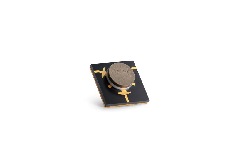
Two dominant structural configurations exist in PCB-level ferrite circulators: the T-Type microstrip circulator and the Y-Type microstrip circulator. Both rely on biased ferrite physics, but their field symmetry and impedance transitions differ, which influences bandwidth, isolation, insertion loss, and practical PCB layout constraints. This article provides a structured, engineering-level comparison, including the often-overlooked impact of manufacturing tolerances and assembly repeatability.
If you want to compare real product families while reading, you can reference the Typical Microstrip Circulator Series and the compact-module context provided by SMD Drop-in Circulators.
1. Microstrip Circulator Fundamentals
A microstrip circulator is a three-port passive non-reciprocal device that routes energy from Port 1 → Port 2, Port 2 → Port 3, and Port 3 → Port 1 (or the reverse direction) depending on bias orientation. The core mechanism is gyromagnetic behavior in ferrite material under a DC magnetic bias field. Once biased, ferrite exhibits an anisotropic permeability tensor, enabling directional coupling between ports.
Compared to coaxial and waveguide circulators, microstrip circulators are optimized for planar PCB integration, making them valuable where size, weight, and assembly compatibility matter. However, PCB-level integration introduces additional parasitics, and those parasitics may shift matching, ripple isolation curves, or reduce effective bandwidth if not controlled.
2. Structural Differences: T-Type vs Y-Type Microstrip Circulator
2.1 T-Type Microstrip Circulator Structure
The T-Type microstrip circulator uses a three-arm junction arranged in a T-like geometry. This topology is often favored for compact routing, shorter trace length, and simpler port transitions when PCB space is limited. While the T-shaped arrangement can be implemented in multiple variants, its practical advantage is that it frequently reduces board complexity and eases integration into tight RF modules.
Typical structural characteristics include:
- Compact geometry: Often easier to fit into space-constrained RF boards.
- Routing simplicity: Port transitions can be shorter and more direct.
- Moderate broadband capability: Commonly optimized for narrower-to-mid fractional bandwidth requirements.
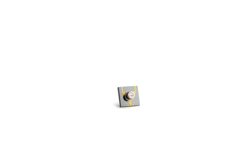
2.2 Y-Type Microstrip Circulator Structure
The Y-Type microstrip circulator adopts a symmetric three-branch configuration, typically spaced at 120 degrees. This geometry improves electromagnetic symmetry at the junction and can enhance broadband matching stability when implemented with consistent substrate and ground references. Because many broadband behaviors depend on symmetry, the Y-type topology is widely used when performance consistency across a wide band is prioritized.
- Improved field symmetry: More uniform energy distribution across the ferrite region.
- Enhanced broadband stability: Better impedance behavior at band edges when properly matched.
- Higher sensitivity to imbalance: Symmetry requirements impose stricter layout and manufacturing discipline.
3. Bandwidth Performance and What Actually Limits It
Bandwidth is typically defined as the frequency range over which insertion loss (IL), isolation (ISO), and return loss (VSWR) remain within acceptable limits. In microstrip circulators, bandwidth is not a single-variable outcome. It emerges from the combined effect of ferrite material parameters, the bias field strength and uniformity, junction geometry, and PCB parasitics.
A practical engineering view of bandwidth limitation includes:
- Impedance transition stability: Broad bandwidth requires consistent effective impedance from port traces into the junction region.
- Mode purity at the junction: Unwanted mode excitation can introduce ripple in S-parameters.
- Ferrite resonance behavior: Material linewidth and bias tuning determine loss and isolation shape.
- PCB parasitics: Pads, solder, vias, and housing boundaries create frequency-dependent loading.
| Comparison Item | T-Type Microstrip Circulator | Y-Type Microstrip Circulator |
|---|---|---|
| Typical Fractional Bandwidth | ~10–20% | ~20–30%+ (design-dependent) |
| Edge Frequency Stability | Moderate | Higher (with good symmetry) |
| Broadband Matching Effort | Often simpler, may require tuning | More sensitive, symmetry-driven |
| Layout Sensitivity | Lower | Higher |
A common engineering rule-of-thumb is that Y-type structures can produce flatter performance across the band, especially near frequency edges, because symmetry reduces localized impedance variation. That said, if a Y-type layout is not well balanced, its “theoretical advantage” can evaporate quickly.
4. Isolation and Insertion Loss: Mechanisms and Practical Stability
Isolation is a system-protection parameter. In transmit/receive modules and power-sensitive chains, isolation determines how much reflected energy leaks back toward the transmitter port. In practice, engineers care about isolation not only at a single frequency point but across the operating band and across environmental shifts (temperature, mounting pressure, bias drift).
Insertion loss is typically a combination of ferrite loss (material linewidth, resonance tuning), conductor loss, dielectric loss, and mismatch-related loss across the junction transitions. A good broadband microstrip circulator must control all of these while maintaining stable isolation.
Typical performance expectations in many RF bands are:
- Isolation: commonly ~18–23 dB for many implementations; broadband-optimized designs may maintain higher stability across the band.
- Insertion loss: often ~0.3–0.6 dB (highly band/material dependent).
- Return loss / VSWR: strongly affected by PCB transitions, pads, solder, and ground continuity.
5. PCB Layout and Integration: What Engineers Should Control First
PCB layout is where microstrip circulator designs either succeed quietly or fail noisily. The same part number can perform differently on two boards because PCB parasitics change effective impedance transitions and junction boundary conditions. In microstrip implementations, even small physical changes translate into measurable S-parameter shifts.
5.1 The Four Most Important PCB Variables
- Ground reference integrity: via fences, ground continuity, and return current paths must be stable.
- Port transition geometry: pads, launch geometry, and line width continuity govern reflection performance.
- Symmetry discipline (especially for Y-Type): equal-length routing and consistent ground environments matter.
- Solder and assembly parasitics: solder volume introduces parasitic capacitance and inductive discontinuities.
5.2 T-Type Layout Characteristics
- Routing simplicity: often easier to implement in compact modules.
- Lower sensitivity to minor imbalance: small asymmetries may not catastrophically degrade performance.
- Useful in space-driven designs: common in compact RF modules and dense integration layouts.
5.3 Y-Type Layout Characteristics
- Symmetry requirement: branch balance and identical port environments are critical.
- Higher sensitivity to imbalance: mismatched trace widths or inconsistent via placement can create ripple.
- Best suited for broadband modules: when layout symmetry is achievable and controlled.
If your board is extremely space constrained and requires more forgiving integration behavior, T-type structures often provide practical advantages. For wideband performance where symmetry can be protected in design and production, Y-type configurations can deliver stronger bandwidth consistency.
6. High-Frequency Behavior (Ku/Ka/mmWave): Why Symmetry Becomes Harder
At higher frequencies, physical dimensions become electrically larger. This makes the junction region more sensitive to small geometry changes, material variations, and assembly tolerances. When you move into Ku/Ka or approach millimeter-wave regimes, trace width tolerance, substrate thickness stability, and housing boundary conditions become more critical.
In many high-frequency implementations, Y-type geometries can maintain better electromagnetic balance and deliver more stable broadband behavior. However, achieving that stability demands tighter manufacturing control and more careful PCB integration.
In systems where waveguide integration is used for lower loss and higher power handling, waveguide alternatives may be evaluated: Junction Waveguide Circulators.
7. Application Scenarios: Which One Fits Better?
- Wideband radar front-ends: Y-Type microstrip circulator is often preferred due to broadband stability and edge performance.
- 5G/6G carrier aggregation: Y-Type can support multi-band performance if integration symmetry is maintained.
- Compact RF modules: T-Type offers routing and footprint advantages when space dominates decisions.
- Test & measurement systems: both structures work, selection depends on bandwidth target and board constraints.
8. Manufacturing Process and Tolerance Control Impact Analysis
While electromagnetic theory defines the ideal behavior of a microstrip circulator, real-world performance is ultimately determined by manufacturing precision. In both T-Type and Y-Type microstrip circulators, dimensional tolerance, ferrite material consistency, and assembly accuracy directly influence bandwidth stability, insertion loss flatness, and isolation performance.
8.1 Ferrite Material Control
The ferrite disc is the core functional element in any microstrip circulator. Its saturation magnetization (Ms), linewidth (ΔH), and dielectric constant uniformity significantly impact non-reciprocal behavior. Small variations can shift resonance, introduce loss, or change the “shape” of the isolation curve across frequency.
- Saturation Magnetization Variation: affects center frequency alignment and tuning margin.
- Linewidth Broadening: increases insertion loss and reduces isolation peak performance.
- Material Uniformity: influences broadband impedance stability and ripple behavior.
In Y-Type microstrip circulators, where electromagnetic symmetry is central to wideband performance, ferrite parameter uniformity becomes even more important. If material consistency drifts, isolation peaks can shift and broadband flatness may degrade.
8.2 PCB Dimensional Tolerance
Microstrip line width tolerance directly impacts characteristic impedance (Z0). At microwave frequencies, even small absolute variations can shift impedance enough to produce measurable return loss and isolation ripple. Substrate thickness and dielectric constant variations add another layer of uncertainty.
In T-Type microstrip circulators, minor dimensional asymmetry may degrade isolation slightly but often remains manageable. In Y-Type microstrip circulators, trace imbalance disrupts angular symmetry, potentially reducing broadband matching stability.
- Trace Width Tolerance: tighter control improves repeatability (example engineering target: ±0.02 mm depending on stack-up and frequency).
- Substrate Thickness Variation: thickness stability supports consistent effective dielectric constant.
- Dielectric Constant Uniformity: reduces frequency-dependent mismatch and ripple.
8.3 Magnet Bias Alignment
Proper magnet bias alignment is essential to achieve optimal gyromagnetic behavior. Off-center placement or tilt introduces field imbalance, which can shift the operating point and distort isolation/insertion loss behavior. Mechanical fixtures, assembly pressure control, and magnet seating repeatability all matter.
Y-Type microstrip circulators are generally more sensitive to magnet misalignment because their broadband behavior depends on balanced field distribution. T-type designs may tolerate minor offsets slightly better, but alignment remains critical for production stability.
8.4 Solder Volume and Parasitic Capacitance
During PCB integration, solder joints and pad geometry create parasitic capacitance at port interfaces. Excess solder can increase capacitive loading, shifting impedance matching and affecting VSWR. This effect is often visible as increased ripple or degraded return loss near band edges.
In high-frequency designs, small additional capacitance can shift matching enough to change the isolation curve shape. Y-Type microstrip circulators, due to symmetry requirements, tend to be more sensitive to inconsistent solder volumes across ports.
8.5 CNC Machining and Metal Housing Precision
For packaged microstrip circulators, metal housing and ground reference surfaces affect boundary conditions and return current behavior. CNC machining precision influences flatness and seating pressure distribution. Surface plating uniformity also impacts conductivity and long-term stability.
- Housing flatness: flatness helps maintain consistent ferrite-to-ground spacing and mechanical pressure distribution.
- Plating consistency: uniform conductivity supports stable RF ground behavior.
- Magnetic circuit integrity: consistent mechanical assembly supports bias repeatability.
In wideband Y-Type designs, uneven seating or housing-induced asymmetry can perturb field distribution. Manufacturing control in mechanical dimensions is therefore part of RF performance control.
8.6 Yield Stability and Production Repeatability
From a manufacturing perspective, T-Type microstrip circulators often achieve higher yield tolerance because the topology is less symmetry-dependent. Y-Type microstrip circulators can deliver superior bandwidth and isolation stability, but require tighter process control to achieve consistent results across lots.
This trade-off explains why Y-type structures are frequently used in high-performance broadband RF systems, while T-type structures remain attractive in compact designs where routing simplicity and robust manufacturability are prioritized.
Conclusion
T-Type and Y-Type microstrip circulators both serve essential roles in RF system architecture. The optimal selection depends on bandwidth requirements, isolation stability expectations, PCB space constraints, operating frequency range, and the level of manufacturing/assembly control available.
For moderate bandwidth and compact integration, the T-Type microstrip circulator often provides a practical, routing-friendly solution with strong repeatability. For broadband and high-frequency systems, the Y-Type microstrip circulator offers superior electromagnetic symmetry and improved stability across band edges—especially when PCB symmetry and manufacturing tolerances are tightly controlled.
FAQ
Which structure provides wider bandwidth in a microstrip circulator?
In many broadband designs, Y-Type microstrip circulators can achieve wider fractional bandwidth due to symmetrical geometry, provided the layout and manufacturing tolerances preserve symmetry.
Is a T-Type microstrip circulator easier for PCB routing?
Yes. T-Type structures often require less symmetry discipline and can fit more easily into space-constrained layouts.
Why does solder volume change microstrip circulator performance?
Excess solder introduces parasitic capacitance and discontinuities at port transitions, impacting VSWR and potentially reducing isolation flatness near frequency edges.
What manufacturing factor most commonly causes lot-to-lot variation?
Ferrite parameter consistency (such as linewidth and saturation magnetization), combined with magnet alignment repeatability and PCB stack-up tolerance, are common contributors to lot-to-lot variation.
Where can I compare typical microstrip circulator options?
You can review typical PCB-integrated families here: Typical Microstrip Circulator Series.
References
1. D. M. Pozar, Microwave Engineering, 4th Edition.
2. IEEE Transactions on Microwave Theory and Techniques (MTT) – ferrite non-reciprocal device research and circulator implementations.
3. IEEE ferrite device technical papers on gyromagnetic resonance and biased ferrite permeability tensors.
4. HzBeat internal RF validation practices (VNA-based S-parameter verification and production repeatability checks).

Sara
Sara is a Brand Specialist at Hzbeat, focusing on RF & microwave industry communications. She transforms complex technologies into accessible insights, helping global readers understand the value of circulators, isolators, and other key components.