What Happens If an RF Circulator Is Connected Backwards?
Learn what happens when an RF circulator is connected backwards, including signal loss, poor isolation, load overheating, and possible PA or receiver damage.
 Updated on: Aug 24, 2026
 Author:
.jpg)
Introduction
An RF circulator is a directional microwave component. If its ports are connected incorrectly, RF power may be routed to the wrong destination instead of simply passing through in the opposite direction.
The result can be severe signal loss, termination overheating, poor isolation, or damage to a power amplifier or receiver. Understanding the circulator's fixed signal path is therefore essential before connecting a transmitter, antenna, receiver, or termination load.
How Does an RF Circulator Route Signals?
A three-port RF circulator is a passive, non-reciprocal device that directs RF energy sequentially between its ports. A typical circulation direction is:
- A signal entering Port 1 exits through Port 2.
- A signal entering Port 2 exits through Port 3.
- A signal entering Port 3 exits through Port 1.
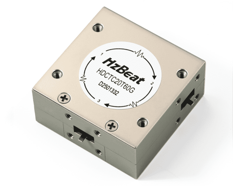
The reverse paths provide isolation rather than normal transmission. Because both clockwise and counterclockwise circulators are available, engineers should check the port numbers, circulation arrow, product label, and datasheet before installation.
For more information, read How to Identify the Port Direction of an RF Circulator.
What Happens When the Input and Output Are Reversed?
Consider a circulator designed to transmit from Port 1 to Port 2, with Port 3 connected to a 50-ohm termination. If the RF source is connected to Port 2 and the intended output remains connected to Port 1, the signal will not travel efficiently from Port 2 to Port 1.
Instead, most of the RF power follows the normal circulation path from Port 2 to Port 3. This incorrect connection can cause the following problems.
1. Severe Output Signal Loss
Port 2 to Port 1 is the isolated direction in this example. Only a small leakage signal may reach the intended output, making the system appear to have unusually high insertion loss.
- Very low transmitted power
- Reduced communication range
- Abnormally high measured insertion loss
- Poor receiver sensitivity
- Unstable or unexpected test results
2. RF Power Is Directed Into the Termination
If Port 3 is fitted with a matched load, power entering Port 2 will be routed toward that load. During low-power testing, this may only cause a missing output signal. In a high-power system, however, the load may overheat or fail if it is not rated for the applied continuous or peak power.
3. Power-Amplifier Protection May Be Lost
RF circulators are commonly used to prevent reflected energy from returning to a power amplifier. When the ports are connected incorrectly, this protection path may no longer work as intended.
- Power-amplifier overheating
- Gain compression or unstable operation
- Reduced component lifetime
- Permanent damage to the PA output stage
4. Transmitter-to-Receiver Isolation Can Decrease
In systems where a transmitter and receiver share one antenna, incorrect port assignments can direct transmitter energy toward the receiver. This may cause receiver compression, desensitization, interference, inaccurate measurements, or permanent front-end damage.
Will a Backward Connection Always Damage the Circulator?
Not necessarily. Connecting a circulator incorrectly does not automatically damage its ferrite junction, especially during a low-power test. The actual risk depends on:
- Input power and reflected-power levels
- Termination power rating
- Operating frequency and port VSWR
- Circulator peak and average power capacity
- Pulse width, duty cycle, mounting, and heat dissipation
In many cases, the third-port termination, power amplifier, or receiver is at greater immediate risk than the circulator itself. Prolonged operation with excessive absorbed or reflected power can nevertheless overheat the circulator and degrade its RF performance.
Can the Ports Be Rotated Without Causing a Problem?
It is important to distinguish between reversing two connections and rotating all three port assignments correctly. For a circulator with a Port 1 → Port 2 → Port 3 → Port 1 direction, the following configurations all use a forward transmission path:
- Input Port 1, output Port 2, termination Port 3
- Input Port 2, output Port 3, termination Port 1
- Input Port 3, output Port 1, termination Port 2
Common Signs of an Incorrect Circulator Connection
- Output power is much lower than expected.
- The source produces normal power, but little reaches the output.
- The third-port termination becomes hot very quickly.
- Measured insertion loss is much higher than the datasheet value.
- Reverse isolation is lower than expected.
- Reflected power or VSWR is unusually high.
- The receiver becomes overloaded during transmission.
How to Check and Correct the Installation
- Identify Port 1, Port 2, and Port 3 on the circulator.
- Check the circulation arrow printed on the product label.
- Confirm whether the device is clockwise or counterclockwise.
- Compare the system connections with the datasheet diagram.
- Install a suitable 50-ohm termination on the required port.
- Verify that the load can handle the expected RF power.
- Use a vector network analyzer to check each transmission path.
- Begin testing at low power before increasing to full power.
- Monitor the circulator and termination temperatures.
See the RF Isolator and Circulator Installation Guide for additional recommendations.
Conclusion
When an RF circulator is connected backwards, the signal does not simply pass through with a small additional loss. It follows the circulator's fixed routing direction and may be delivered to the termination or another unintended circuit.
The resulting problems can include severe signal attenuation, termination overheating, poor isolation, receiver overload, and loss of power-amplifier protection. Always verify the port numbers, circulation arrow, operating frequency, termination rating, and datasheet connection diagram before applying RF power.
For RF circulator selection, customization, or technical support, visit the HzBeat official website.
Frequently Asked Questions
Can an RF circulator work in both directions?
No. A standard RF circulator has a fixed circulation direction. Clockwise and counterclockwise versions may be available, but one device cannot normally reverse its direction during operation.
Why is there almost no output after swapping two ports?
The new connection may place the signal on the circulator's isolation path. Most of the energy will travel to the next port in the specified circulation direction instead of reaching the intended output.
Can an incorrect connection damage the 50-ohm load?
Yes. If the circulator sends transmitter power directly into the load, the load may overheat or fail when its average or peak power rating is exceeded.
How can I confirm the correct signal direction?
Check the arrow, port numbering, product label, and datasheet. A vector network analyzer can also verify which adjacent-port path has low insertion loss and which path provides isolation.
References
- HzBeat. How Do I Identify the Port Direction of an RF Circulator?
- HzBeat. RF Isolator & Circulator Installation Guide: Direction, Matching, Heat Dissipation, and Testing.
- TDK Product Center. Isolators/Circulators CU Series: Product Overview.
- Engineering LibreTexts. Ferrite Components: Circulators and Isolators.
Recommended Products
 Article Tags
Keith Wong
Marketing Director, Chengdu Hertz Electronic Technology Co., Ltd. (Hzbeat)
Keith has over 18 years in the RF components industry, focusing on the intersection of technology, healthcare applications, and global market trends.