Home/ Microstrip Circulator/ Surface Mount Technology Microstrip Circulator
Surface Mount Technology Microstrip Circulator
X Band, Ku Band. (8GHz-18GHz)
- The Surface Mount Technology (SMT) Microstrip Circulator series is designed for easy integration into surface mount assemblies, providing flexibility for a wide range of electronic applications.
- These circulators are characterized by their compact size, high performance, and compatibility with SMT assembly processes.
- They are ideal for modern communication systems, phased array antennas, and RF front-end modules where space-saving and efficient assembly are critical. The SMT Microstrip Circulator series ensures reliable signal routing and isolation with seamless SMT-based integration.
Key Features & Advantages
- Ultra-Compact and Lightweight: Employs LTCC and integrated design, allowing for very small sizes (e.g., 3.2x2.5x1.2mm) and weights of just a few tenths of a gram, greatly saving PCB space. Ideal for highly integrated modules.
- Surface-Mount Package: Compliant with SMT process requirements, can be directly mounted onto PCBs via reflow soldering. Highly suitable for automated, large-scale production, significantly reducing assembly cost and time.
- Excellent High-Frequency Performance: The planar structure delivers outstanding performance in high-frequency and ultra-high-frequency bands (e.g., C, X, Ku, Ka bands), with low parasitic parameters and stable performance.
- High Reliability: All-solid-state structure, no moving parts, resistant to vibration and shock. LTCC material offers good thermal stability and long operational lifetime.
- Excellent Consistency: Manufactured using semiconductor-like processes, offering far better batch-to-batch consistency and product repeatability than coaxial or stripline circulators.
Typical Applications
- Radar Systems: Used in T/R Modules to switch between transmit and receive paths, protecting the low-noise amplifier from high-power transmit signals.
- Mobile Communication Infrastructure: Isolation of transmit and receive signals in 5G/4G Base Station Massive MIMO antenna systems.
- Point-to-Point / Point-to-Multi-point Radios: In microwave relay communication and satellite communication terminals, enabling single-antenna operation for both transmit and receive functions.
- Test & Measurement Equipment: Used in equipment like signal sources and spectrum analyzers for signal routing and isolation.
- IoT & Drones: Enables efficient RF signal management in devices with stringent size and weight constraints.
Electrical Performance Table and Product Appearance
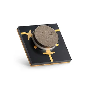
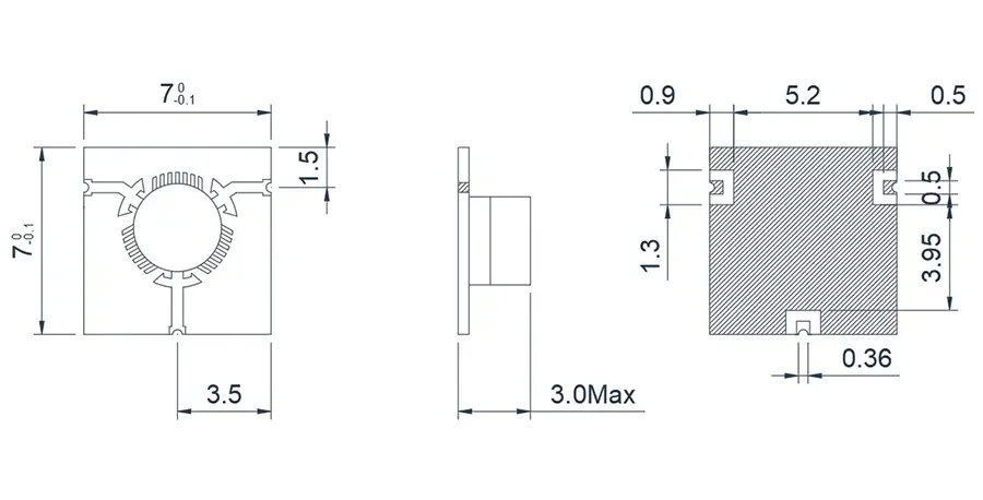
8.0~12.0GHz Surface Mount Technology Microstrip 'T' junction Circulator
Model
Frequency(GHz)
BW Max
Insertion loss(dB) Max
Isolation(dB)Min
VSWR Max
operating temperature(℃ )
PK/CW/RP(Watt)
Direction
HMCTE80T120G⬇
8.0~12.0
FULL
0.6
18
1.3
-55~+85℃
20/10
Clockwise
HMCTF80T120G⬇
8.0~12.0
FULL
0.6
18
1.3
-55~+85℃
20/10
Counter Clockwise
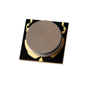
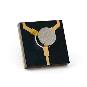
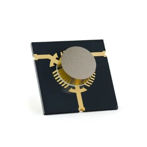
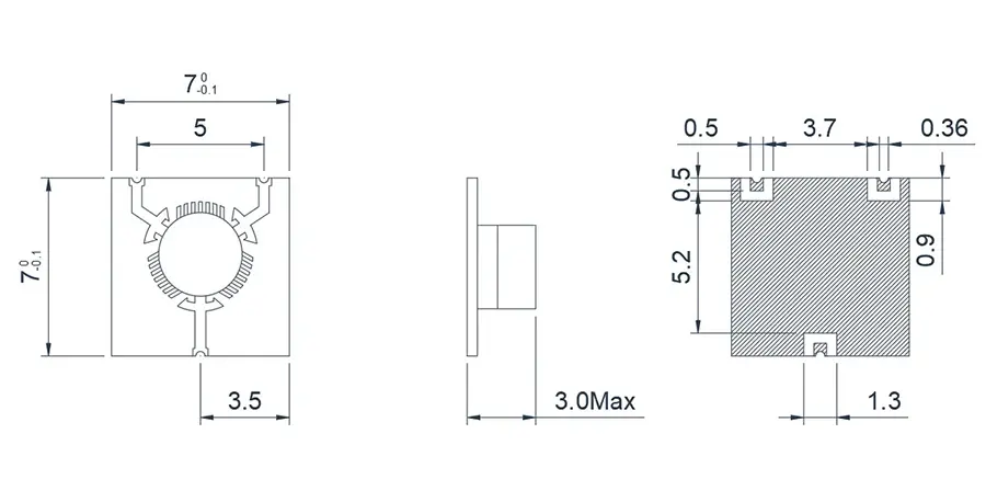
8.0~12.0GHz Surface Mount Technology Microstrip 'Y' junction Circulator
Model
Frequency(GHz)
BW Max
Insertion loss(dB) Max
Isolation(dB)Min
VSWR Max
operating temperature(℃ )
PK/CW/RP(Watt)
Direction
HMCYE80T120G⬇
8.0~12.0
FULL
0.6
18
1.3
-55~+85℃
20/10
Clockwise
HMCYF80T120G⬇
8.0~12.0
FULL
0.6
18
1.3
-55~+85℃
20/10
Counter Clockwise
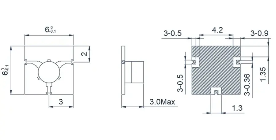
14.0~18.0GHz Surface Mount Technology Microstrip 'T' junction Circulator
Model
Frequency(GHz)
BW Max
Insertion loss(dB) Max
Isolation(dB)Min
VSWR Max
operating temperature(℃ )
PK/CW/RP(Watt)
Direction
HMCTE140T180G⬇
14.0~18.0
FULL
0.6
18
1.3
-55~+85℃
20/10
Clockwise
HMCTF140T180G⬇
14.0~18.0
FULL
0.6
18
1.3
-55~+85℃
20/10
Counter Clockwise
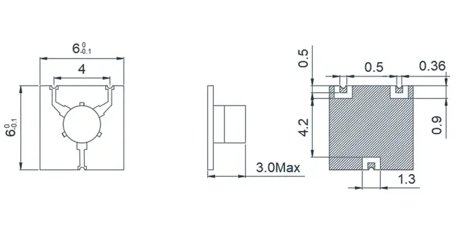
14.0~18.0GHz Surface Mount Technology Microstrip 'Y' junction Circulator
Model
Frequency(GHz)
BW Max
Insertion loss(dB) Max
Isolation(dB)Min
VSWR Max
operating temperature(℃ )
PK/CW/RP(Watt)
Direction
HMCYE140T180G⬇
14.0~18.0
FULL
0.6
18
1.3
-55~+85℃
20/10
Clockwise
HMCYF140T180G⬇
14.0~18.0
FULL
0.6
18
1.3
-55~+85℃
20/10
Counter Clockwise
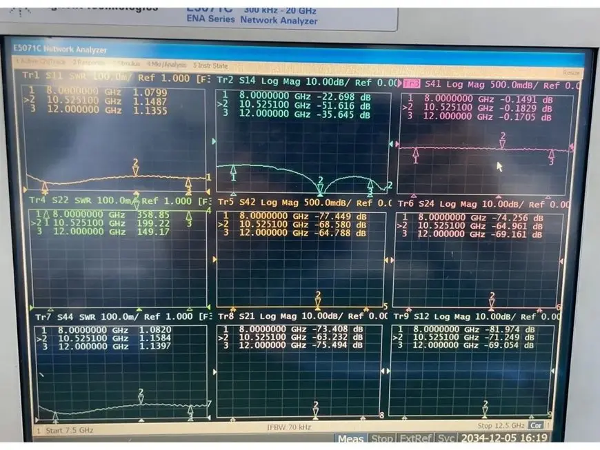
HMCYE80T120G 8.0GHz-12.0GHz
HMCYE80T120G 8.0GHz-12.0GHz
About HzBeat
HzBeat is a leading RF component manufacturer specializing in RF circulators and isolators, as a global supplier of RF circulators and isolators (20MHz–200GHz), we providing microstrip, drop-in, coaxial, and waveguide solutions for communication systems, radar, satellite, and medical imaging.
For detailed technical documentation, sample requests, or customization needs, please do not hesitate to contact us. — we respond within 24 hours to ensure you get precise solutions for your design.
Customization & Selection Guide
- Operating Band:Ensure it covers all frequencies required by your system.
- Power Handling Capacity:Select based on your system's transmit power (average and peak), allowing a certain margin.
- Performance Requirements:Define specific requirements for Insertion Loss, Isolation, and VSWR/Return Loss.
- Environmental Conditions:Consider operating temperature range, vibration, humidity, etc.
- Cost & Delivery:Balance cost and project timeline while meeting performance requirements.
Why Choose Our Product
- Profound Technical Expertise:We have over 18 years of R&D experience in ferrite materials and microwave magnetics.
- Fully Automated Production Lines:Ensure consistent excellence and reliability in every unit.
- Professional Application Support:Our engineering team provides timely technical selection, customization, and failure analysis services.
- Competitive Pricing & Lead Times:Economies of scale from mass production enable us to respond quickly to your orders.
Related Products
Questions? Feel Free to Reach Out Via Message.
Tell us frequency band, target IL/Isolation/VSWR, power level and timeline — we’ll match the best topology and deliver S-parameters.We will contact you within 24 hours.
| Model | Frequency(GHz) | BW Max | Insertion loss(dB) Max | Isolation(dB)Min | VSWR Max | operating temperature(℃ ) | PK/CW/RP(Watt) | Direction |
|---|---|---|---|---|---|---|---|---|
| HMCTE80T120G⬇ | 8.0~12.0 | FULL | 0.6 | 18 | 1.3 | -55~+85℃ | 20/10 | Clockwise |
| HMCTF80T120G⬇ | 8.0~12.0 | FULL | 0.6 | 18 | 1.3 | -55~+85℃ | 20/10 | Counter Clockwise |
8.0~12.0GHz Surface Mount Technology Microstrip 'Y' junction Circulator
Model
Frequency(GHz)
BW Max
Insertion loss(dB) Max
Isolation(dB)Min
VSWR Max
operating temperature(℃ )
PK/CW/RP(Watt)
Direction
HMCYE80T120G⬇
8.0~12.0
FULL
0.6
18
1.3
-55~+85℃
20/10
Clockwise
HMCYF80T120G⬇
8.0~12.0
FULL
0.6
18
1.3
-55~+85℃
20/10
Counter Clockwise
14.0~18.0GHz Surface Mount Technology Microstrip 'T' junction Circulator
Model
Frequency(GHz)
BW Max
Insertion loss(dB) Max
Isolation(dB)Min
VSWR Max
operating temperature(℃ )
PK/CW/RP(Watt)
Direction
HMCTE140T180G⬇
14.0~18.0
FULL
0.6
18
1.3
-55~+85℃
20/10
Clockwise
HMCTF140T180G⬇
14.0~18.0
FULL
0.6
18
1.3
-55~+85℃
20/10
Counter Clockwise
14.0~18.0GHz Surface Mount Technology Microstrip 'Y' junction Circulator
Model
Frequency(GHz)
BW Max
Insertion loss(dB) Max
Isolation(dB)Min
VSWR Max
operating temperature(℃ )
PK/CW/RP(Watt)
Direction
HMCYE140T180G⬇
14.0~18.0
FULL
0.6
18
1.3
-55~+85℃
20/10
Clockwise
HMCYF140T180G⬇
14.0~18.0
FULL
0.6
18
1.3
-55~+85℃
20/10
Counter Clockwise
HMCYE80T120G 8.0GHz-12.0GHz
HMCYE80T120G 8.0GHz-12.0GHz
About HzBeat
HzBeat is a leading RF component manufacturer specializing in RF circulators and isolators, as a global supplier of RF circulators and isolators (20MHz–200GHz), we providing microstrip, drop-in, coaxial, and waveguide solutions for communication systems, radar, satellite, and medical imaging.
For detailed technical documentation, sample requests, or customization needs, please do not hesitate to contact us. — we respond within 24 hours to ensure you get precise solutions for your design.
Customization & Selection Guide
- Operating Band:Ensure it covers all frequencies required by your system.
- Power Handling Capacity:Select based on your system's transmit power (average and peak), allowing a certain margin.
- Performance Requirements:Define specific requirements for Insertion Loss, Isolation, and VSWR/Return Loss.
- Environmental Conditions:Consider operating temperature range, vibration, humidity, etc.
- Cost & Delivery:Balance cost and project timeline while meeting performance requirements.
Why Choose Our Product
- Profound Technical Expertise:We have over 18 years of R&D experience in ferrite materials and microwave magnetics.
- Fully Automated Production Lines:Ensure consistent excellence and reliability in every unit.
- Professional Application Support:Our engineering team provides timely technical selection, customization, and failure analysis services.
- Competitive Pricing & Lead Times:Economies of scale from mass production enable us to respond quickly to your orders.
Related Products
Questions? Feel Free to Reach Out Via Message.
Tell us frequency band, target IL/Isolation/VSWR, power level and timeline — we’ll match the best topology and deliver S-parameters.We will contact you within 24 hours.
| Model | Frequency(GHz) | BW Max | Insertion loss(dB) Max | Isolation(dB)Min | VSWR Max | operating temperature(℃ ) | PK/CW/RP(Watt) | Direction |
|---|---|---|---|---|---|---|---|---|
| HMCYE80T120G⬇ | 8.0~12.0 | FULL | 0.6 | 18 | 1.3 | -55~+85℃ | 20/10 | Clockwise |
| HMCYF80T120G⬇ | 8.0~12.0 | FULL | 0.6 | 18 | 1.3 | -55~+85℃ | 20/10 | Counter Clockwise |
14.0~18.0GHz Surface Mount Technology Microstrip 'T' junction Circulator
Model
Frequency(GHz)
BW Max
Insertion loss(dB) Max
Isolation(dB)Min
VSWR Max
operating temperature(℃ )
PK/CW/RP(Watt)
Direction
HMCTE140T180G⬇
14.0~18.0
FULL
0.6
18
1.3
-55~+85℃
20/10
Clockwise
HMCTF140T180G⬇
14.0~18.0
FULL
0.6
18
1.3
-55~+85℃
20/10
Counter Clockwise
14.0~18.0GHz Surface Mount Technology Microstrip 'Y' junction Circulator
Model
Frequency(GHz)
BW Max
Insertion loss(dB) Max
Isolation(dB)Min
VSWR Max
operating temperature(℃ )
PK/CW/RP(Watt)
Direction
HMCYE140T180G⬇
14.0~18.0
FULL
0.6
18
1.3
-55~+85℃
20/10
Clockwise
HMCYF140T180G⬇
14.0~18.0
FULL
0.6
18
1.3
-55~+85℃
20/10
Counter Clockwise
HMCYE80T120G 8.0GHz-12.0GHz
HMCYE80T120G 8.0GHz-12.0GHz
About HzBeat
HzBeat is a leading RF component manufacturer specializing in RF circulators and isolators, as a global supplier of RF circulators and isolators (20MHz–200GHz), we providing microstrip, drop-in, coaxial, and waveguide solutions for communication systems, radar, satellite, and medical imaging.
For detailed technical documentation, sample requests, or customization needs, please do not hesitate to contact us. — we respond within 24 hours to ensure you get precise solutions for your design.
Customization & Selection Guide
- Operating Band:Ensure it covers all frequencies required by your system.
- Power Handling Capacity:Select based on your system's transmit power (average and peak), allowing a certain margin.
- Performance Requirements:Define specific requirements for Insertion Loss, Isolation, and VSWR/Return Loss.
- Environmental Conditions:Consider operating temperature range, vibration, humidity, etc.
- Cost & Delivery:Balance cost and project timeline while meeting performance requirements.
Why Choose Our Product
- Profound Technical Expertise:We have over 18 years of R&D experience in ferrite materials and microwave magnetics.
- Fully Automated Production Lines:Ensure consistent excellence and reliability in every unit.
- Professional Application Support:Our engineering team provides timely technical selection, customization, and failure analysis services.
- Competitive Pricing & Lead Times:Economies of scale from mass production enable us to respond quickly to your orders.
Related Products
Questions? Feel Free to Reach Out Via Message.
Tell us frequency band, target IL/Isolation/VSWR, power level and timeline — we’ll match the best topology and deliver S-parameters.We will contact you within 24 hours.
| Model | Frequency(GHz) | BW Max | Insertion loss(dB) Max | Isolation(dB)Min | VSWR Max | operating temperature(℃ ) | PK/CW/RP(Watt) | Direction |
|---|---|---|---|---|---|---|---|---|
| HMCTE140T180G⬇ | 14.0~18.0 | FULL | 0.6 | 18 | 1.3 | -55~+85℃ | 20/10 | Clockwise |
| HMCTF140T180G⬇ | 14.0~18.0 | FULL | 0.6 | 18 | 1.3 | -55~+85℃ | 20/10 | Counter Clockwise |
14.0~18.0GHz Surface Mount Technology Microstrip 'Y' junction Circulator
Model
Frequency(GHz)
BW Max
Insertion loss(dB) Max
Isolation(dB)Min
VSWR Max
operating temperature(℃ )
PK/CW/RP(Watt)
Direction
HMCYE140T180G⬇
14.0~18.0
FULL
0.6
18
1.3
-55~+85℃
20/10
Clockwise
HMCYF140T180G⬇
14.0~18.0
FULL
0.6
18
1.3
-55~+85℃
20/10
Counter Clockwise
HMCYE80T120G 8.0GHz-12.0GHz
HMCYE80T120G 8.0GHz-12.0GHz
About HzBeat
HzBeat is a leading RF component manufacturer specializing in RF circulators and isolators, as a global supplier of RF circulators and isolators (20MHz–200GHz), we providing microstrip, drop-in, coaxial, and waveguide solutions for communication systems, radar, satellite, and medical imaging.
For detailed technical documentation, sample requests, or customization needs, please do not hesitate to contact us. — we respond within 24 hours to ensure you get precise solutions for your design.
Customization & Selection Guide
- Operating Band:Ensure it covers all frequencies required by your system.
- Power Handling Capacity:Select based on your system's transmit power (average and peak), allowing a certain margin.
- Performance Requirements:Define specific requirements for Insertion Loss, Isolation, and VSWR/Return Loss.
- Environmental Conditions:Consider operating temperature range, vibration, humidity, etc.
- Cost & Delivery:Balance cost and project timeline while meeting performance requirements.
Why Choose Our Product
- Profound Technical Expertise:We have over 18 years of R&D experience in ferrite materials and microwave magnetics.
- Fully Automated Production Lines:Ensure consistent excellence and reliability in every unit.
- Professional Application Support:Our engineering team provides timely technical selection, customization, and failure analysis services.
- Competitive Pricing & Lead Times:Economies of scale from mass production enable us to respond quickly to your orders.
Related Products
Questions? Feel Free to Reach Out Via Message.
Tell us frequency band, target IL/Isolation/VSWR, power level and timeline — we’ll match the best topology and deliver S-parameters.We will contact you within 24 hours.
| Model | Frequency(GHz) | BW Max | Insertion loss(dB) Max | Isolation(dB)Min | VSWR Max | operating temperature(℃ ) | PK/CW/RP(Watt) | Direction |
|---|---|---|---|---|---|---|---|---|
| HMCYE140T180G⬇ | 14.0~18.0 | FULL | 0.6 | 18 | 1.3 | -55~+85℃ | 20/10 | Clockwise |
| HMCYF140T180G⬇ | 14.0~18.0 | FULL | 0.6 | 18 | 1.3 | -55~+85℃ | 20/10 | Counter Clockwise |
HMCYE80T120G 8.0GHz-12.0GHz
HMCYE80T120G 8.0GHz-12.0GHz
About HzBeat
HzBeat is a leading RF component manufacturer specializing in RF circulators and isolators, as a global supplier of RF circulators and isolators (20MHz–200GHz), we providing microstrip, drop-in, coaxial, and waveguide solutions for communication systems, radar, satellite, and medical imaging.
For detailed technical documentation, sample requests, or customization needs, please do not hesitate to contact us. — we respond within 24 hours to ensure you get precise solutions for your design.
Customization & Selection Guide
- Operating Band:Ensure it covers all frequencies required by your system.
- Power Handling Capacity:Select based on your system's transmit power (average and peak), allowing a certain margin.
- Performance Requirements:Define specific requirements for Insertion Loss, Isolation, and VSWR/Return Loss.
- Environmental Conditions:Consider operating temperature range, vibration, humidity, etc.
- Cost & Delivery:Balance cost and project timeline while meeting performance requirements.
Why Choose Our Product
- Profound Technical Expertise:We have over 18 years of R&D experience in ferrite materials and microwave magnetics.
- Fully Automated Production Lines:Ensure consistent excellence and reliability in every unit.
- Professional Application Support:Our engineering team provides timely technical selection, customization, and failure analysis services.
- Competitive Pricing & Lead Times:Economies of scale from mass production enable us to respond quickly to your orders.