High power handling capability: This waveguide component is designed to withstand high-power microwave and millimeter-wave signals, making it suitable for applications requiring high-power transmission.
Differential phase shift: The ability to introduce a specific phase shift, typically used for modulating and controlling the phase of microwave signals.
Waveguide structure: Waveguides are structures used to transmit microwave and millimeter-wave signals, offering low transmission loss and high power handling capability.
Typical Applications
Radar Systems (High-power transmission with precise phase control)
Communication Base Stations (Phase control and high-power RF signal management)
Satellite Communication Systems (High-power waveguide transmission and phase shifting)
High-Power RF Systems (Thermal and electromagnetic compatibility critical applications)
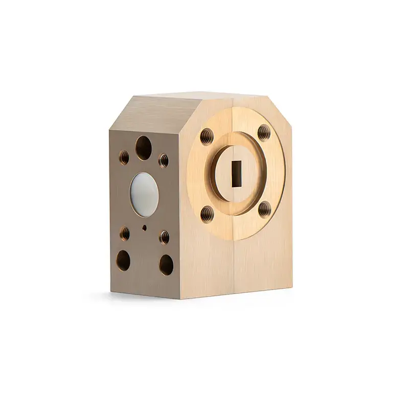
Electrical Performance Table and Product Appearance
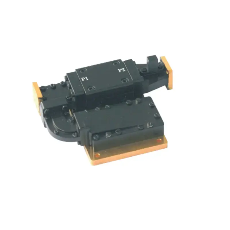
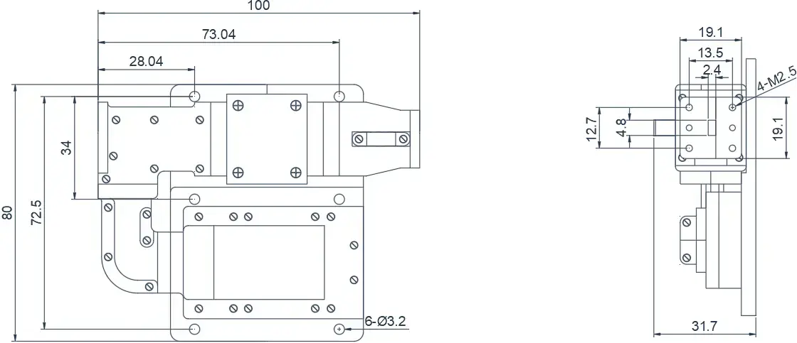
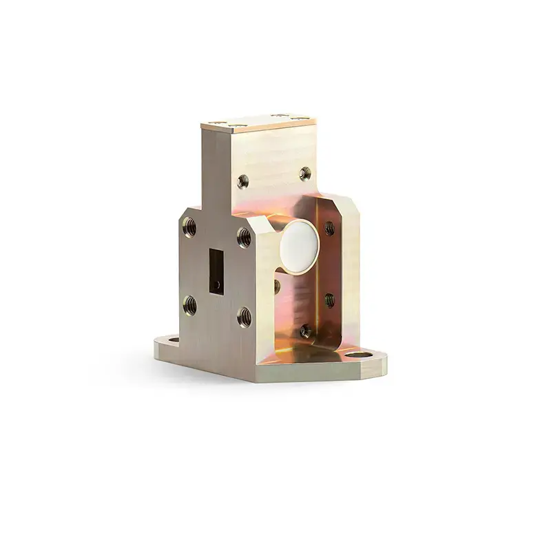
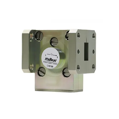
The following are case products of the Differential Phase-Shift High Power Waveguide Isolator. The Differential Phase-Shift High Power Waveguide Isolator is capable of withstanding high-power microwave signals and offers a power handling capacity improvement of one to two orders of magnitude compared to regular junction circulators.These products can be customized according to your requirements.
HzBeat is a leading RF component manufacturer specializing in RF circulators and isolators, as a global supplier of RF circulators and isolators (20MHz–200GHz), we providing microstrip, drop-in, coaxial, and waveguide solutions for communication systems, radar, satellite, and medical imaging.
For detailed technical documentation, sample requests, or customization needs, please do not hesitate to contact us. — we respond within 24 hours to ensure you get precise solutions for your design.
Customization & Selection Guide
Operating Band:Ensure it covers all frequencies required by your system.
Power Handling Capacity:Select based on your system's transmit power (average and peak), allowing a certain margin.
Performance Requirements:Define specific requirements for Insertion Loss, Isolation, and VSWR/Return Loss.
Environmental Conditions:Consider operating temperature range, vibration, humidity, etc.
Cost & Delivery:Balance cost and project timeline while meeting performance requirements.
Why Choose Our Product
Profound Technical Expertise:We have over 18 years of R&D experience in ferrite materials and microwave magnetics.
Fully Automated Production Lines:Ensure consistent excellence and reliability in every unit.
Professional Application Support:Our engineering team provides timely technical selection, customization, and failure analysis services.
Competitive Pricing & Lead Times:Economies of scale from mass production enable us to respond quickly to your orders.
Tell us frequency band, target IL/Isolation/VSWR, power level and timeline — we’ll match the best topology and deliver S-parameters.We will contact you within 24 hours.