Home/ Drop-in Isolator/ High Power Drop-in Isolator
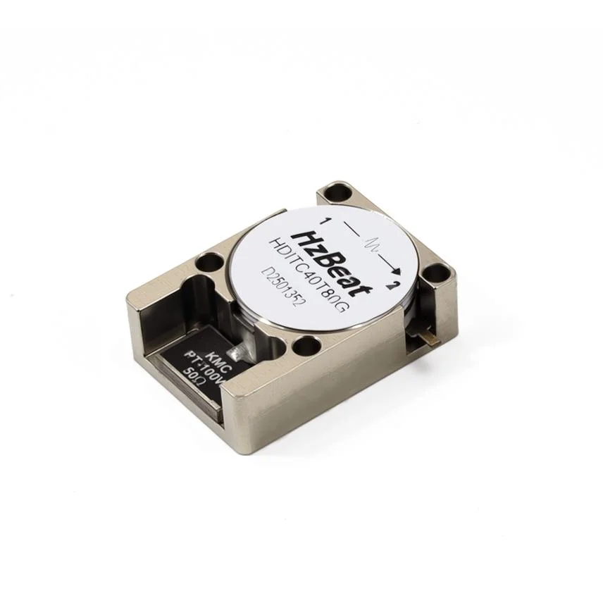
High Power Drop-in Isolator
Custom design.
- High Power Drop-in Isolator is a crucial component in RF and microwave systems, specifically designed to handle high power levels while providing efficient signal isolation and protection against unwanted reflections.
Key Features & Advantages
- High Power Handling: Supports high average (hundreds of W to kW) and peak power (up to tens of kW).
- Low Passive Intermodulation (PIM): Utilizes special materials and processes to ensure low PIM performance in carrier aggregation and high-power multi-carrier scenarios, preventing interference with communication signals.
- Excellent Thermal Design: Metal-ceramic structures with air or liquid cooling for efficient heat dissipation.
- High Isolation and Stability: Maintains excellent isolation and stable insertion loss even under high power and varying temperature conditions.
- Robust Construction: Designed to withstand vibrations and shocks in harsh environments (e.g., cellular tower tops, airborne platforms).
Typical Applications
- Macro & Small Cell Mobile Communication Base Stations
- Broadcast Transmission Systems
- Defense Radar & Electronic Warfare Systems
- Industrial Heating & Scientific Research Equipment
- Medical Equipment
Electrical Performance Table and Product Appearance
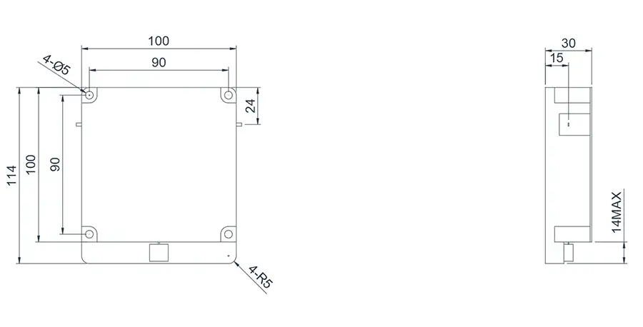
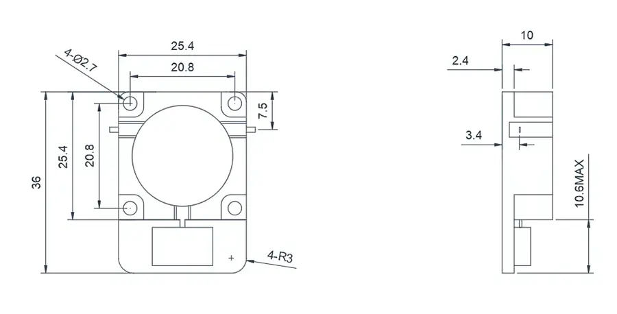
0.05~0.2GHz High Power Drop-in Isolator
Product Overview
The following products are case examples of VHF band High Power Drop-in Isolators. Product dimensions and port configurations can be customized based on high-power requirements and high reflected power.
Model
Frequency(GHz)
BW Max
Insertion loss(dB) Max
Isolation(dB)Min
VSWR Max
operating temperature(℃ )
PK/CW/RP(Watt)
Direction
HDITC50T200M-H⬇
0.05~0.2
10%
0.4
20
1.20
-55~+85℃
5000/500
Clockwise
HDITD50T200M-H⬇
0.05~0.2
10%
0.4
20
1.20
-55~+85℃
5000/500
Counter Clockwise
0.1~0.3GHz High Power Drop-in Isolator
Product Overview
Here are commonly used products of Drop-in Circulator. This product covers the VHF~UHF band range with a relative bandwidth of up to 10~20%. Dimensions and frequency bands can be customized based on your requirements.
Model
Frequency(GHz)
BW Max
Insertion loss(dB) Max
Isolation(dB)Min
VSWR Max
operating temperature(℃ )
PK/CW/RP(Watt)
Direction
HDITC01T03G-H⬇
0.1~0.3
10%
0.4
20
1.20
-55~+85℃
5000/500
Clockwise
HDITD01T03G-H⬇
0.1~0.3
10%
0.4
20
1.20
-55~+85℃
5000/500
Counter Clockwise
0.25~0.6GHz High Power Drop-in Isolator
Product Overview
The following products are case examples of VHF to UHF band High Power Drop-in Isolators. Product dimensions and port configurations can be customized based on high-power requirements and high reflected power.
Model
Frequency(GHz)
BW Max
Insertion loss(dB) Max
Isolation(dB)Min
VSWR Max
operating temperature(℃ )
PK/CW/RP(Watt)
Direction
HDITC01T03G-H⬇
0.25~0.6
10%
0.4
20
1.20
-55~+85℃
5000/500
Clockwise
HDITD01T03G-H⬇
0.25~0.6
10%
0.4
20
1.20
-55~+85℃
5000/500
Counter Clockwise
0.5~1.0GHz High Power Drop-in Isolator
Product Overview
The following products are case examples of UHF band High Power Drop-in Isolators. Product dimensions and port configurations can be customized based on high-power requirements and high reflected power.
Model
Frequency(GHz)
BW Max
Insertion loss(dB) Max
Isolation(dB)Min
VSWR Max
operating temperature(℃ )
PK/CW/RP(Watt)
Direction
HDITC05T10G-H⬇
0.5~1.0
10%
0.4
20
1.20
-55~+85℃
2000/200
Clockwise
HDITD05T10G-H⬇
0.5~1.0
10%
0.4
20
1.20
-55~+85℃
2000/200
Counter Clockwise
1.0~6.0GHz High Power Drop-in Isolator
Product Overview
Model
Frequency(GHz)
BW Max
Insertion loss(dB) Max
Isolation(dB)Min
VSWR Max
operating temperature(℃ )
PK/CW/RP(Watt)
Direction
HDITC10T60G-H⬇
1.0~6.0
10%
0.4
20
1.20
-40~+70℃
2000/200
Clockwise
HDITD10T60G-H⬇
1.0~6.0
10%
0.4
20
1.20
-40~+70℃
2000/200
Counter Clockwise
1.0~6.0GHz High Power Drop-in Isolator
Product Overview
Model
Frequency(GHz)
BW Max
Insertion loss(dB) Max
Isolation(dB)Min
VSWR Max
operating temperature(℃ )
PK/CW/RP(Watt)
Direction
HDITC10T60G-H⬇
1.0~6.0
10%
0.4
20
1.20
-40~+70℃
1000/100/100
Clockwise
HDITD10T60G-H⬇
1.0~6.0
10%
0.4
20
1.20
-40~+70℃
1000/100/100
Counter Clockwise
1.6~3.4GHz High Power Drop-in Isolator
Product Overview
Model
Frequency(GHz)
BW Max
Insertion loss(dB) Max
Isolation(dB)Min
VSWR Max
operating temperature(℃ )
PK/CW/RP(Watt)
Direction
HDITC40T60G-H⬇
1.6~3.4
10%
0.4
20
1.20
-40~+70℃
1000/100
Clockwise
HDITD40T60G-H⬇
1.6~3.4
10%
0.4
20
1.20
-40~+70℃
1000/100
Counter Clockwise
4.0~6.0GHz High Power Drop-in Isolator
Product Overview
Model
Frequency(GHz)
BW Max
Insertion loss(dB) Max
Isolation(dB)Min
VSWR Max
operating temperature(℃ )
PK/CW/RP(Watt)
Direction
HDITC40T60G-H⬇
4.0~6.0
10%
0.4
20
1.2
-40~+70℃
500/80
Clockwise
HDITD40T60G-H⬇
4.0~6.0
10%
0.4
20
1.2
-40~+70℃
500/80
Counter Clockwise
5.0~12.0GHz High Power Drop-in Isolator
Product Overview
Model
Frequency(GHz)
BW Max
Insertion loss(dB) Max
Isolation(dB)Min
VSWR Max
operating temperature(℃ )
PK/CW/RP(Watt)
Direction
HDITC40T60G-H⬇
4.0~6.0
10%
0.4
20
1.2
-40~+70℃
500/80
Clockwise
HDITC40T60G-H⬇
4.0~6.0
10%
0.4
20
1.2
-40~+70℃
500/80
Counter Clockwise
About HzBeat
HzBeat is a leading RF component manufacturer specializing in RF circulators and isolators, as a global supplier of RF circulators and isolators (20MHz–200GHz), we providing microstrip, drop-in, coaxial, and waveguide solutions for communication systems, radar, satellite, and medical imaging.
For detailed technical documentation, sample requests, or customization needs, please do not hesitate to contact us. — we respond within 24 hours to ensure you get precise solutions for your design.
Customization & Selection Guide
- Operating Band:Ensure it covers all frequencies required by your system.
- Power Handling Capacity:Select based on your system's transmit power (average and peak), allowing a certain margin.
- Performance Requirements:Define specific requirements for Insertion Loss, Isolation, and VSWR/Return Loss.
- Environmental Conditions:Consider operating temperature range, vibration, humidity, etc.
- Cost & Delivery:Balance cost and project timeline while meeting performance requirements.
Why Choose Our Product
- Profound Technical Expertise:We have over 18 years of R&D experience in ferrite materials and microwave magnetics.
- Fully Automated Production Lines:Ensure consistent excellence and reliability in every unit.
- Professional Application Support:Our engineering team provides timely technical selection, customization, and failure analysis services.
- Competitive Pricing & Lead Times:Economies of scale from mass production enable us to respond quickly to your orders.
Related Products
Questions? Feel Free to Reach Out Via Message.
Tell us frequency band, target IL/Isolation/VSWR, power level and timeline — we’ll match the best topology and deliver S-parameters.We will contact you within 24 hours.
Product Overview
The following products are case examples of VHF band High Power Drop-in Isolators. Product dimensions and port configurations can be customized based on high-power requirements and high reflected power.
| Model | Frequency(GHz) | BW Max | Insertion loss(dB) Max | Isolation(dB)Min | VSWR Max | operating temperature(℃ ) | PK/CW/RP(Watt) | Direction |
|---|---|---|---|---|---|---|---|---|
| HDITC50T200M-H⬇ | 0.05~0.2 | 10% | 0.4 | 20 | 1.20 | -55~+85℃ | 5000/500 | Clockwise |
| HDITD50T200M-H⬇ | 0.05~0.2 | 10% | 0.4 | 20 | 1.20 | -55~+85℃ | 5000/500 | Counter Clockwise |
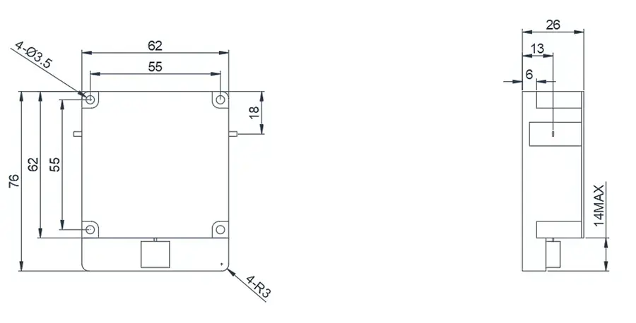
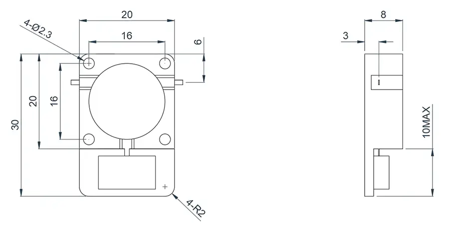
0.1~0.3GHz High Power Drop-in Isolator
Product Overview
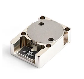
Here are commonly used products of Drop-in Circulator. This product covers the VHF~UHF band range with a relative bandwidth of up to 10~20%. Dimensions and frequency bands can be customized based on your requirements.
Model
Frequency(GHz)
BW Max
Insertion loss(dB) Max
Isolation(dB)Min
VSWR Max
operating temperature(℃ )
PK/CW/RP(Watt)
Direction
HDITC01T03G-H⬇
0.1~0.3
10%
0.4
20
1.20
-55~+85℃
5000/500
Clockwise
HDITD01T03G-H⬇
0.1~0.3
10%
0.4
20
1.20
-55~+85℃
5000/500
Counter Clockwise
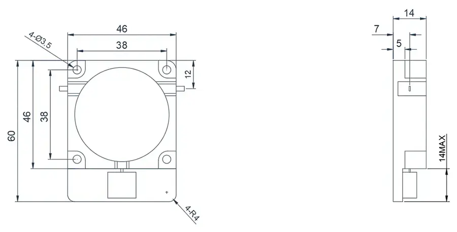
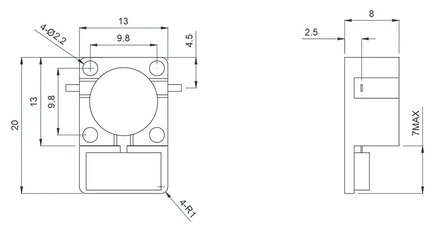
0.25~0.6GHz High Power Drop-in Isolator
Product Overview
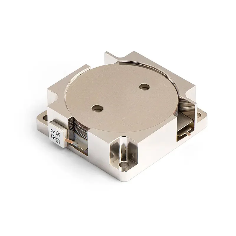
The following products are case examples of VHF to UHF band High Power Drop-in Isolators. Product dimensions and port configurations can be customized based on high-power requirements and high reflected power.
Model
Frequency(GHz)
BW Max
Insertion loss(dB) Max
Isolation(dB)Min
VSWR Max
operating temperature(℃ )
PK/CW/RP(Watt)
Direction
HDITC01T03G-H⬇
0.25~0.6
10%
0.4
20
1.20
-55~+85℃
5000/500
Clockwise
HDITD01T03G-H⬇
0.25~0.6
10%
0.4
20
1.20
-55~+85℃
5000/500
Counter Clockwise
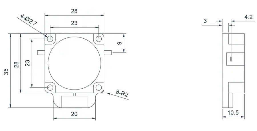
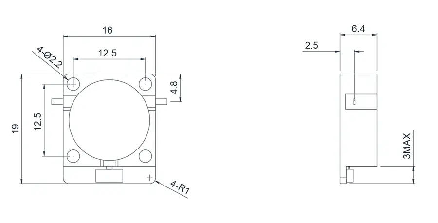
0.5~1.0GHz High Power Drop-in Isolator
Product Overview
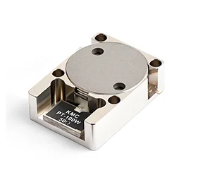
The following products are case examples of UHF band High Power Drop-in Isolators. Product dimensions and port configurations can be customized based on high-power requirements and high reflected power.
Model
Frequency(GHz)
BW Max
Insertion loss(dB) Max
Isolation(dB)Min
VSWR Max
operating temperature(℃ )
PK/CW/RP(Watt)
Direction
HDITC05T10G-H⬇
0.5~1.0
10%
0.4
20
1.20
-55~+85℃
2000/200
Clockwise
HDITD05T10G-H⬇
0.5~1.0
10%
0.4
20
1.20
-55~+85℃
2000/200
Counter Clockwise
1.0~6.0GHz High Power Drop-in Isolator
Product Overview
Model
Frequency(GHz)
BW Max
Insertion loss(dB) Max
Isolation(dB)Min
VSWR Max
operating temperature(℃ )
PK/CW/RP(Watt)
Direction
HDITC10T60G-H⬇
1.0~6.0
10%
0.4
20
1.20
-40~+70℃
2000/200
Clockwise
HDITD10T60G-H⬇
1.0~6.0
10%
0.4
20
1.20
-40~+70℃
2000/200
Counter Clockwise
1.0~6.0GHz High Power Drop-in Isolator
Product Overview
Model
Frequency(GHz)
BW Max
Insertion loss(dB) Max
Isolation(dB)Min
VSWR Max
operating temperature(℃ )
PK/CW/RP(Watt)
Direction
HDITC10T60G-H⬇
1.0~6.0
10%
0.4
20
1.20
-40~+70℃
1000/100/100
Clockwise
HDITD10T60G-H⬇
1.0~6.0
10%
0.4
20
1.20
-40~+70℃
1000/100/100
Counter Clockwise
1.6~3.4GHz High Power Drop-in Isolator
Product Overview
Model
Frequency(GHz)
BW Max
Insertion loss(dB) Max
Isolation(dB)Min
VSWR Max
operating temperature(℃ )
PK/CW/RP(Watt)
Direction
HDITC40T60G-H⬇
1.6~3.4
10%
0.4
20
1.20
-40~+70℃
1000/100
Clockwise
HDITD40T60G-H⬇
1.6~3.4
10%
0.4
20
1.20
-40~+70℃
1000/100
Counter Clockwise
4.0~6.0GHz High Power Drop-in Isolator
Product Overview
Model
Frequency(GHz)
BW Max
Insertion loss(dB) Max
Isolation(dB)Min
VSWR Max
operating temperature(℃ )
PK/CW/RP(Watt)
Direction
HDITC40T60G-H⬇
4.0~6.0
10%
0.4
20
1.2
-40~+70℃
500/80
Clockwise
HDITD40T60G-H⬇
4.0~6.0
10%
0.4
20
1.2
-40~+70℃
500/80
Counter Clockwise
5.0~12.0GHz High Power Drop-in Isolator
Product Overview
Model
Frequency(GHz)
BW Max
Insertion loss(dB) Max
Isolation(dB)Min
VSWR Max
operating temperature(℃ )
PK/CW/RP(Watt)
Direction
HDITC40T60G-H⬇
4.0~6.0
10%
0.4
20
1.2
-40~+70℃
500/80
Clockwise
HDITC40T60G-H⬇
4.0~6.0
10%
0.4
20
1.2
-40~+70℃
500/80
Counter Clockwise
About HzBeat
HzBeat is a leading RF component manufacturer specializing in RF circulators and isolators, as a global supplier of RF circulators and isolators (20MHz–200GHz), we providing microstrip, drop-in, coaxial, and waveguide solutions for communication systems, radar, satellite, and medical imaging.
For detailed technical documentation, sample requests, or customization needs, please do not hesitate to contact us. — we respond within 24 hours to ensure you get precise solutions for your design.
Customization & Selection Guide
- Operating Band:Ensure it covers all frequencies required by your system.
- Power Handling Capacity:Select based on your system's transmit power (average and peak), allowing a certain margin.
- Performance Requirements:Define specific requirements for Insertion Loss, Isolation, and VSWR/Return Loss.
- Environmental Conditions:Consider operating temperature range, vibration, humidity, etc.
- Cost & Delivery:Balance cost and project timeline while meeting performance requirements.
Why Choose Our Product
- Profound Technical Expertise:We have over 18 years of R&D experience in ferrite materials and microwave magnetics.
- Fully Automated Production Lines:Ensure consistent excellence and reliability in every unit.
- Professional Application Support:Our engineering team provides timely technical selection, customization, and failure analysis services.
- Competitive Pricing & Lead Times:Economies of scale from mass production enable us to respond quickly to your orders.
Related Products
Questions? Feel Free to Reach Out Via Message.
Tell us frequency band, target IL/Isolation/VSWR, power level and timeline — we’ll match the best topology and deliver S-parameters.We will contact you within 24 hours.
Product Overview
Here are commonly used products of Drop-in Circulator. This product covers the VHF~UHF band range with a relative bandwidth of up to 10~20%. Dimensions and frequency bands can be customized based on your requirements.
| Model | Frequency(GHz) | BW Max | Insertion loss(dB) Max | Isolation(dB)Min | VSWR Max | operating temperature(℃ ) | PK/CW/RP(Watt) | Direction |
|---|---|---|---|---|---|---|---|---|
| HDITC01T03G-H⬇ | 0.1~0.3 | 10% | 0.4 | 20 | 1.20 | -55~+85℃ | 5000/500 | Clockwise |
| HDITD01T03G-H⬇ | 0.1~0.3 | 10% | 0.4 | 20 | 1.20 | -55~+85℃ | 5000/500 | Counter Clockwise |
0.25~0.6GHz High Power Drop-in Isolator
Product Overview
The following products are case examples of VHF to UHF band High Power Drop-in Isolators. Product dimensions and port configurations can be customized based on high-power requirements and high reflected power.
Model
Frequency(GHz)
BW Max
Insertion loss(dB) Max
Isolation(dB)Min
VSWR Max
operating temperature(℃ )
PK/CW/RP(Watt)
Direction
HDITC01T03G-H⬇
0.25~0.6
10%
0.4
20
1.20
-55~+85℃
5000/500
Clockwise
HDITD01T03G-H⬇
0.25~0.6
10%
0.4
20
1.20
-55~+85℃
5000/500
Counter Clockwise
0.5~1.0GHz High Power Drop-in Isolator
Product Overview
The following products are case examples of UHF band High Power Drop-in Isolators. Product dimensions and port configurations can be customized based on high-power requirements and high reflected power.
Model
Frequency(GHz)
BW Max
Insertion loss(dB) Max
Isolation(dB)Min
VSWR Max
operating temperature(℃ )
PK/CW/RP(Watt)
Direction
HDITC05T10G-H⬇
0.5~1.0
10%
0.4
20
1.20
-55~+85℃
2000/200
Clockwise
HDITD05T10G-H⬇
0.5~1.0
10%
0.4
20
1.20
-55~+85℃
2000/200
Counter Clockwise
1.0~6.0GHz High Power Drop-in Isolator
Product Overview
Model
Frequency(GHz)
BW Max
Insertion loss(dB) Max
Isolation(dB)Min
VSWR Max
operating temperature(℃ )
PK/CW/RP(Watt)
Direction
HDITC10T60G-H⬇
1.0~6.0
10%
0.4
20
1.20
-40~+70℃
2000/200
Clockwise
HDITD10T60G-H⬇
1.0~6.0
10%
0.4
20
1.20
-40~+70℃
2000/200
Counter Clockwise
1.0~6.0GHz High Power Drop-in Isolator
Product Overview
Model
Frequency(GHz)
BW Max
Insertion loss(dB) Max
Isolation(dB)Min
VSWR Max
operating temperature(℃ )
PK/CW/RP(Watt)
Direction
HDITC10T60G-H⬇
1.0~6.0
10%
0.4
20
1.20
-40~+70℃
1000/100/100
Clockwise
HDITD10T60G-H⬇
1.0~6.0
10%
0.4
20
1.20
-40~+70℃
1000/100/100
Counter Clockwise
1.6~3.4GHz High Power Drop-in Isolator
Product Overview
Model
Frequency(GHz)
BW Max
Insertion loss(dB) Max
Isolation(dB)Min
VSWR Max
operating temperature(℃ )
PK/CW/RP(Watt)
Direction
HDITC40T60G-H⬇
1.6~3.4
10%
0.4
20
1.20
-40~+70℃
1000/100
Clockwise
HDITD40T60G-H⬇
1.6~3.4
10%
0.4
20
1.20
-40~+70℃
1000/100
Counter Clockwise
4.0~6.0GHz High Power Drop-in Isolator
Product Overview
Model
Frequency(GHz)
BW Max
Insertion loss(dB) Max
Isolation(dB)Min
VSWR Max
operating temperature(℃ )
PK/CW/RP(Watt)
Direction
HDITC40T60G-H⬇
4.0~6.0
10%
0.4
20
1.2
-40~+70℃
500/80
Clockwise
HDITD40T60G-H⬇
4.0~6.0
10%
0.4
20
1.2
-40~+70℃
500/80
Counter Clockwise
5.0~12.0GHz High Power Drop-in Isolator
Product Overview
Model
Frequency(GHz)
BW Max
Insertion loss(dB) Max
Isolation(dB)Min
VSWR Max
operating temperature(℃ )
PK/CW/RP(Watt)
Direction
HDITC40T60G-H⬇
4.0~6.0
10%
0.4
20
1.2
-40~+70℃
500/80
Clockwise
HDITC40T60G-H⬇
4.0~6.0
10%
0.4
20
1.2
-40~+70℃
500/80
Counter Clockwise
About HzBeat
HzBeat is a leading RF component manufacturer specializing in RF circulators and isolators, as a global supplier of RF circulators and isolators (20MHz–200GHz), we providing microstrip, drop-in, coaxial, and waveguide solutions for communication systems, radar, satellite, and medical imaging.
For detailed technical documentation, sample requests, or customization needs, please do not hesitate to contact us. — we respond within 24 hours to ensure you get precise solutions for your design.
Customization & Selection Guide
- Operating Band:Ensure it covers all frequencies required by your system.
- Power Handling Capacity:Select based on your system's transmit power (average and peak), allowing a certain margin.
- Performance Requirements:Define specific requirements for Insertion Loss, Isolation, and VSWR/Return Loss.
- Environmental Conditions:Consider operating temperature range, vibration, humidity, etc.
- Cost & Delivery:Balance cost and project timeline while meeting performance requirements.
Why Choose Our Product
- Profound Technical Expertise:We have over 18 years of R&D experience in ferrite materials and microwave magnetics.
- Fully Automated Production Lines:Ensure consistent excellence and reliability in every unit.
- Professional Application Support:Our engineering team provides timely technical selection, customization, and failure analysis services.
- Competitive Pricing & Lead Times:Economies of scale from mass production enable us to respond quickly to your orders.
Related Products
Questions? Feel Free to Reach Out Via Message.
Tell us frequency band, target IL/Isolation/VSWR, power level and timeline — we’ll match the best topology and deliver S-parameters.We will contact you within 24 hours.
Product Overview
The following products are case examples of VHF to UHF band High Power Drop-in Isolators. Product dimensions and port configurations can be customized based on high-power requirements and high reflected power.
| Model | Frequency(GHz) | BW Max | Insertion loss(dB) Max | Isolation(dB)Min | VSWR Max | operating temperature(℃ ) | PK/CW/RP(Watt) | Direction |
|---|---|---|---|---|---|---|---|---|
| HDITC01T03G-H⬇ | 0.25~0.6 | 10% | 0.4 | 20 | 1.20 | -55~+85℃ | 5000/500 | Clockwise |
| HDITD01T03G-H⬇ | 0.25~0.6 | 10% | 0.4 | 20 | 1.20 | -55~+85℃ | 5000/500 | Counter Clockwise |
0.5~1.0GHz High Power Drop-in Isolator
Product Overview
The following products are case examples of UHF band High Power Drop-in Isolators. Product dimensions and port configurations can be customized based on high-power requirements and high reflected power.
Model
Frequency(GHz)
BW Max
Insertion loss(dB) Max
Isolation(dB)Min
VSWR Max
operating temperature(℃ )
PK/CW/RP(Watt)
Direction
HDITC05T10G-H⬇
0.5~1.0
10%
0.4
20
1.20
-55~+85℃
2000/200
Clockwise
HDITD05T10G-H⬇
0.5~1.0
10%
0.4
20
1.20
-55~+85℃
2000/200
Counter Clockwise
1.0~6.0GHz High Power Drop-in Isolator
Product Overview
Model
Frequency(GHz)
BW Max
Insertion loss(dB) Max
Isolation(dB)Min
VSWR Max
operating temperature(℃ )
PK/CW/RP(Watt)
Direction
HDITC10T60G-H⬇
1.0~6.0
10%
0.4
20
1.20
-40~+70℃
2000/200
Clockwise
HDITD10T60G-H⬇
1.0~6.0
10%
0.4
20
1.20
-40~+70℃
2000/200
Counter Clockwise
1.0~6.0GHz High Power Drop-in Isolator
Product Overview
Model
Frequency(GHz)
BW Max
Insertion loss(dB) Max
Isolation(dB)Min
VSWR Max
operating temperature(℃ )
PK/CW/RP(Watt)
Direction
HDITC10T60G-H⬇
1.0~6.0
10%
0.4
20
1.20
-40~+70℃
1000/100/100
Clockwise
HDITD10T60G-H⬇
1.0~6.0
10%
0.4
20
1.20
-40~+70℃
1000/100/100
Counter Clockwise
1.6~3.4GHz High Power Drop-in Isolator
Product Overview
Model
Frequency(GHz)
BW Max
Insertion loss(dB) Max
Isolation(dB)Min
VSWR Max
operating temperature(℃ )
PK/CW/RP(Watt)
Direction
HDITC40T60G-H⬇
1.6~3.4
10%
0.4
20
1.20
-40~+70℃
1000/100
Clockwise
HDITD40T60G-H⬇
1.6~3.4
10%
0.4
20
1.20
-40~+70℃
1000/100
Counter Clockwise
4.0~6.0GHz High Power Drop-in Isolator
Product Overview
Model
Frequency(GHz)
BW Max
Insertion loss(dB) Max
Isolation(dB)Min
VSWR Max
operating temperature(℃ )
PK/CW/RP(Watt)
Direction
HDITC40T60G-H⬇
4.0~6.0
10%
0.4
20
1.2
-40~+70℃
500/80
Clockwise
HDITD40T60G-H⬇
4.0~6.0
10%
0.4
20
1.2
-40~+70℃
500/80
Counter Clockwise
5.0~12.0GHz High Power Drop-in Isolator
Product Overview
Model
Frequency(GHz)
BW Max
Insertion loss(dB) Max
Isolation(dB)Min
VSWR Max
operating temperature(℃ )
PK/CW/RP(Watt)
Direction
HDITC40T60G-H⬇
4.0~6.0
10%
0.4
20
1.2
-40~+70℃
500/80
Clockwise
HDITC40T60G-H⬇
4.0~6.0
10%
0.4
20
1.2
-40~+70℃
500/80
Counter Clockwise
About HzBeat
HzBeat is a leading RF component manufacturer specializing in RF circulators and isolators, as a global supplier of RF circulators and isolators (20MHz–200GHz), we providing microstrip, drop-in, coaxial, and waveguide solutions for communication systems, radar, satellite, and medical imaging.
For detailed technical documentation, sample requests, or customization needs, please do not hesitate to contact us. — we respond within 24 hours to ensure you get precise solutions for your design.
Customization & Selection Guide
- Operating Band:Ensure it covers all frequencies required by your system.
- Power Handling Capacity:Select based on your system's transmit power (average and peak), allowing a certain margin.
- Performance Requirements:Define specific requirements for Insertion Loss, Isolation, and VSWR/Return Loss.
- Environmental Conditions:Consider operating temperature range, vibration, humidity, etc.
- Cost & Delivery:Balance cost and project timeline while meeting performance requirements.
Why Choose Our Product
- Profound Technical Expertise:We have over 18 years of R&D experience in ferrite materials and microwave magnetics.
- Fully Automated Production Lines:Ensure consistent excellence and reliability in every unit.
- Professional Application Support:Our engineering team provides timely technical selection, customization, and failure analysis services.
- Competitive Pricing & Lead Times:Economies of scale from mass production enable us to respond quickly to your orders.
Related Products
Questions? Feel Free to Reach Out Via Message.
Tell us frequency band, target IL/Isolation/VSWR, power level and timeline — we’ll match the best topology and deliver S-parameters.We will contact you within 24 hours.
Product Overview
The following products are case examples of UHF band High Power Drop-in Isolators. Product dimensions and port configurations can be customized based on high-power requirements and high reflected power.
| Model | Frequency(GHz) | BW Max | Insertion loss(dB) Max | Isolation(dB)Min | VSWR Max | operating temperature(℃ ) | PK/CW/RP(Watt) | Direction |
|---|---|---|---|---|---|---|---|---|
| HDITC05T10G-H⬇ | 0.5~1.0 | 10% | 0.4 | 20 | 1.20 | -55~+85℃ | 2000/200 | Clockwise |
| HDITD05T10G-H⬇ | 0.5~1.0 | 10% | 0.4 | 20 | 1.20 | -55~+85℃ | 2000/200 | Counter Clockwise |
1.0~6.0GHz High Power Drop-in Isolator
Product Overview
Model
Frequency(GHz)
BW Max
Insertion loss(dB) Max
Isolation(dB)Min
VSWR Max
operating temperature(℃ )
PK/CW/RP(Watt)
Direction
HDITC10T60G-H⬇
1.0~6.0
10%
0.4
20
1.20
-40~+70℃
2000/200
Clockwise
HDITD10T60G-H⬇
1.0~6.0
10%
0.4
20
1.20
-40~+70℃
2000/200
Counter Clockwise
1.0~6.0GHz High Power Drop-in Isolator
Product Overview
Model
Frequency(GHz)
BW Max
Insertion loss(dB) Max
Isolation(dB)Min
VSWR Max
operating temperature(℃ )
PK/CW/RP(Watt)
Direction
HDITC10T60G-H⬇
1.0~6.0
10%
0.4
20
1.20
-40~+70℃
1000/100/100
Clockwise
HDITD10T60G-H⬇
1.0~6.0
10%
0.4
20
1.20
-40~+70℃
1000/100/100
Counter Clockwise
1.6~3.4GHz High Power Drop-in Isolator
Product Overview
Model
Frequency(GHz)
BW Max
Insertion loss(dB) Max
Isolation(dB)Min
VSWR Max
operating temperature(℃ )
PK/CW/RP(Watt)
Direction
HDITC40T60G-H⬇
1.6~3.4
10%
0.4
20
1.20
-40~+70℃
1000/100
Clockwise
HDITD40T60G-H⬇
1.6~3.4
10%
0.4
20
1.20
-40~+70℃
1000/100
Counter Clockwise
4.0~6.0GHz High Power Drop-in Isolator
Product Overview
Model
Frequency(GHz)
BW Max
Insertion loss(dB) Max
Isolation(dB)Min
VSWR Max
operating temperature(℃ )
PK/CW/RP(Watt)
Direction
HDITC40T60G-H⬇
4.0~6.0
10%
0.4
20
1.2
-40~+70℃
500/80
Clockwise
HDITD40T60G-H⬇
4.0~6.0
10%
0.4
20
1.2
-40~+70℃
500/80
Counter Clockwise
5.0~12.0GHz High Power Drop-in Isolator
Product Overview
Model
Frequency(GHz)
BW Max
Insertion loss(dB) Max
Isolation(dB)Min
VSWR Max
operating temperature(℃ )
PK/CW/RP(Watt)
Direction
HDITC40T60G-H⬇
4.0~6.0
10%
0.4
20
1.2
-40~+70℃
500/80
Clockwise
HDITC40T60G-H⬇
4.0~6.0
10%
0.4
20
1.2
-40~+70℃
500/80
Counter Clockwise
About HzBeat
HzBeat is a leading RF component manufacturer specializing in RF circulators and isolators, as a global supplier of RF circulators and isolators (20MHz–200GHz), we providing microstrip, drop-in, coaxial, and waveguide solutions for communication systems, radar, satellite, and medical imaging.
For detailed technical documentation, sample requests, or customization needs, please do not hesitate to contact us. — we respond within 24 hours to ensure you get precise solutions for your design.
Customization & Selection Guide
- Operating Band:Ensure it covers all frequencies required by your system.
- Power Handling Capacity:Select based on your system's transmit power (average and peak), allowing a certain margin.
- Performance Requirements:Define specific requirements for Insertion Loss, Isolation, and VSWR/Return Loss.
- Environmental Conditions:Consider operating temperature range, vibration, humidity, etc.
- Cost & Delivery:Balance cost and project timeline while meeting performance requirements.
Why Choose Our Product
- Profound Technical Expertise:We have over 18 years of R&D experience in ferrite materials and microwave magnetics.
- Fully Automated Production Lines:Ensure consistent excellence and reliability in every unit.
- Professional Application Support:Our engineering team provides timely technical selection, customization, and failure analysis services.
- Competitive Pricing & Lead Times:Economies of scale from mass production enable us to respond quickly to your orders.
Related Products
Questions? Feel Free to Reach Out Via Message.
Tell us frequency band, target IL/Isolation/VSWR, power level and timeline — we’ll match the best topology and deliver S-parameters.We will contact you within 24 hours.
Product Overview
| Model | Frequency(GHz) | BW Max | Insertion loss(dB) Max | Isolation(dB)Min | VSWR Max | operating temperature(℃ ) | PK/CW/RP(Watt) | Direction |
|---|---|---|---|---|---|---|---|---|
| HDITC10T60G-H⬇ | 1.0~6.0 | 10% | 0.4 | 20 | 1.20 | -40~+70℃ | 2000/200 | Clockwise |
| HDITD10T60G-H⬇ | 1.0~6.0 | 10% | 0.4 | 20 | 1.20 | -40~+70℃ | 2000/200 | Counter Clockwise |
1.0~6.0GHz High Power Drop-in Isolator
Product Overview
Model
Frequency(GHz)
BW Max
Insertion loss(dB) Max
Isolation(dB)Min
VSWR Max
operating temperature(℃ )
PK/CW/RP(Watt)
Direction
HDITC10T60G-H⬇
1.0~6.0
10%
0.4
20
1.20
-40~+70℃
1000/100/100
Clockwise
HDITD10T60G-H⬇
1.0~6.0
10%
0.4
20
1.20
-40~+70℃
1000/100/100
Counter Clockwise
1.6~3.4GHz High Power Drop-in Isolator
Product Overview
Model
Frequency(GHz)
BW Max
Insertion loss(dB) Max
Isolation(dB)Min
VSWR Max
operating temperature(℃ )
PK/CW/RP(Watt)
Direction
HDITC40T60G-H⬇
1.6~3.4
10%
0.4
20
1.20
-40~+70℃
1000/100
Clockwise
HDITD40T60G-H⬇
1.6~3.4
10%
0.4
20
1.20
-40~+70℃
1000/100
Counter Clockwise
4.0~6.0GHz High Power Drop-in Isolator
Product Overview
Model
Frequency(GHz)
BW Max
Insertion loss(dB) Max
Isolation(dB)Min
VSWR Max
operating temperature(℃ )
PK/CW/RP(Watt)
Direction
HDITC40T60G-H⬇
4.0~6.0
10%
0.4
20
1.2
-40~+70℃
500/80
Clockwise
HDITD40T60G-H⬇
4.0~6.0
10%
0.4
20
1.2
-40~+70℃
500/80
Counter Clockwise
5.0~12.0GHz High Power Drop-in Isolator
Product Overview
Model
Frequency(GHz)
BW Max
Insertion loss(dB) Max
Isolation(dB)Min
VSWR Max
operating temperature(℃ )
PK/CW/RP(Watt)
Direction
HDITC40T60G-H⬇
4.0~6.0
10%
0.4
20
1.2
-40~+70℃
500/80
Clockwise
HDITC40T60G-H⬇
4.0~6.0
10%
0.4
20
1.2
-40~+70℃
500/80
Counter Clockwise
About HzBeat
HzBeat is a leading RF component manufacturer specializing in RF circulators and isolators, as a global supplier of RF circulators and isolators (20MHz–200GHz), we providing microstrip, drop-in, coaxial, and waveguide solutions for communication systems, radar, satellite, and medical imaging.
For detailed technical documentation, sample requests, or customization needs, please do not hesitate to contact us. — we respond within 24 hours to ensure you get precise solutions for your design.
Customization & Selection Guide
- Operating Band:Ensure it covers all frequencies required by your system.
- Power Handling Capacity:Select based on your system's transmit power (average and peak), allowing a certain margin.
- Performance Requirements:Define specific requirements for Insertion Loss, Isolation, and VSWR/Return Loss.
- Environmental Conditions:Consider operating temperature range, vibration, humidity, etc.
- Cost & Delivery:Balance cost and project timeline while meeting performance requirements.
Why Choose Our Product
- Profound Technical Expertise:We have over 18 years of R&D experience in ferrite materials and microwave magnetics.
- Fully Automated Production Lines:Ensure consistent excellence and reliability in every unit.
- Professional Application Support:Our engineering team provides timely technical selection, customization, and failure analysis services.
- Competitive Pricing & Lead Times:Economies of scale from mass production enable us to respond quickly to your orders.
Related Products
Questions? Feel Free to Reach Out Via Message.
Tell us frequency band, target IL/Isolation/VSWR, power level and timeline — we’ll match the best topology and deliver S-parameters.We will contact you within 24 hours.
Product Overview
| Model | Frequency(GHz) | BW Max | Insertion loss(dB) Max | Isolation(dB)Min | VSWR Max | operating temperature(℃ ) | PK/CW/RP(Watt) | Direction |
|---|---|---|---|---|---|---|---|---|
| HDITC10T60G-H⬇ | 1.0~6.0 | 10% | 0.4 | 20 | 1.20 | -40~+70℃ | 1000/100/100 | Clockwise |
| HDITD10T60G-H⬇ | 1.0~6.0 | 10% | 0.4 | 20 | 1.20 | -40~+70℃ | 1000/100/100 | Counter Clockwise |
1.6~3.4GHz High Power Drop-in Isolator
Product Overview
Model
Frequency(GHz)
BW Max
Insertion loss(dB) Max
Isolation(dB)Min
VSWR Max
operating temperature(℃ )
PK/CW/RP(Watt)
Direction
HDITC40T60G-H⬇
1.6~3.4
10%
0.4
20
1.20
-40~+70℃
1000/100
Clockwise
HDITD40T60G-H⬇
1.6~3.4
10%
0.4
20
1.20
-40~+70℃
1000/100
Counter Clockwise
4.0~6.0GHz High Power Drop-in Isolator
Product Overview
Model
Frequency(GHz)
BW Max
Insertion loss(dB) Max
Isolation(dB)Min
VSWR Max
operating temperature(℃ )
PK/CW/RP(Watt)
Direction
HDITC40T60G-H⬇
4.0~6.0
10%
0.4
20
1.2
-40~+70℃
500/80
Clockwise
HDITD40T60G-H⬇
4.0~6.0
10%
0.4
20
1.2
-40~+70℃
500/80
Counter Clockwise
5.0~12.0GHz High Power Drop-in Isolator
Product Overview
Model
Frequency(GHz)
BW Max
Insertion loss(dB) Max
Isolation(dB)Min
VSWR Max
operating temperature(℃ )
PK/CW/RP(Watt)
Direction
HDITC40T60G-H⬇
4.0~6.0
10%
0.4
20
1.2
-40~+70℃
500/80
Clockwise
HDITC40T60G-H⬇
4.0~6.0
10%
0.4
20
1.2
-40~+70℃
500/80
Counter Clockwise
About HzBeat
HzBeat is a leading RF component manufacturer specializing in RF circulators and isolators, as a global supplier of RF circulators and isolators (20MHz–200GHz), we providing microstrip, drop-in, coaxial, and waveguide solutions for communication systems, radar, satellite, and medical imaging.
For detailed technical documentation, sample requests, or customization needs, please do not hesitate to contact us. — we respond within 24 hours to ensure you get precise solutions for your design.
Customization & Selection Guide
- Operating Band:Ensure it covers all frequencies required by your system.
- Power Handling Capacity:Select based on your system's transmit power (average and peak), allowing a certain margin.
- Performance Requirements:Define specific requirements for Insertion Loss, Isolation, and VSWR/Return Loss.
- Environmental Conditions:Consider operating temperature range, vibration, humidity, etc.
- Cost & Delivery:Balance cost and project timeline while meeting performance requirements.
Why Choose Our Product
- Profound Technical Expertise:We have over 18 years of R&D experience in ferrite materials and microwave magnetics.
- Fully Automated Production Lines:Ensure consistent excellence and reliability in every unit.
- Professional Application Support:Our engineering team provides timely technical selection, customization, and failure analysis services.
- Competitive Pricing & Lead Times:Economies of scale from mass production enable us to respond quickly to your orders.
Related Products
Questions? Feel Free to Reach Out Via Message.
Tell us frequency band, target IL/Isolation/VSWR, power level and timeline — we’ll match the best topology and deliver S-parameters.We will contact you within 24 hours.
Product Overview
| Model | Frequency(GHz) | BW Max | Insertion loss(dB) Max | Isolation(dB)Min | VSWR Max | operating temperature(℃ ) | PK/CW/RP(Watt) | Direction |
|---|---|---|---|---|---|---|---|---|
| HDITC40T60G-H⬇ | 1.6~3.4 | 10% | 0.4 | 20 | 1.20 | -40~+70℃ | 1000/100 | Clockwise |
| HDITD40T60G-H⬇ | 1.6~3.4 | 10% | 0.4 | 20 | 1.20 | -40~+70℃ | 1000/100 | Counter Clockwise |
4.0~6.0GHz High Power Drop-in Isolator
Product Overview
Model
Frequency(GHz)
BW Max
Insertion loss(dB) Max
Isolation(dB)Min
VSWR Max
operating temperature(℃ )
PK/CW/RP(Watt)
Direction
HDITC40T60G-H⬇
4.0~6.0
10%
0.4
20
1.2
-40~+70℃
500/80
Clockwise
HDITD40T60G-H⬇
4.0~6.0
10%
0.4
20
1.2
-40~+70℃
500/80
Counter Clockwise
5.0~12.0GHz High Power Drop-in Isolator
Product Overview
Model
Frequency(GHz)
BW Max
Insertion loss(dB) Max
Isolation(dB)Min
VSWR Max
operating temperature(℃ )
PK/CW/RP(Watt)
Direction
HDITC40T60G-H⬇
4.0~6.0
10%
0.4
20
1.2
-40~+70℃
500/80
Clockwise
HDITC40T60G-H⬇
4.0~6.0
10%
0.4
20
1.2
-40~+70℃
500/80
Counter Clockwise
About HzBeat
HzBeat is a leading RF component manufacturer specializing in RF circulators and isolators, as a global supplier of RF circulators and isolators (20MHz–200GHz), we providing microstrip, drop-in, coaxial, and waveguide solutions for communication systems, radar, satellite, and medical imaging.
For detailed technical documentation, sample requests, or customization needs, please do not hesitate to contact us. — we respond within 24 hours to ensure you get precise solutions for your design.
Customization & Selection Guide
- Operating Band:Ensure it covers all frequencies required by your system.
- Power Handling Capacity:Select based on your system's transmit power (average and peak), allowing a certain margin.
- Performance Requirements:Define specific requirements for Insertion Loss, Isolation, and VSWR/Return Loss.
- Environmental Conditions:Consider operating temperature range, vibration, humidity, etc.
- Cost & Delivery:Balance cost and project timeline while meeting performance requirements.
Why Choose Our Product
- Profound Technical Expertise:We have over 18 years of R&D experience in ferrite materials and microwave magnetics.
- Fully Automated Production Lines:Ensure consistent excellence and reliability in every unit.
- Professional Application Support:Our engineering team provides timely technical selection, customization, and failure analysis services.
- Competitive Pricing & Lead Times:Economies of scale from mass production enable us to respond quickly to your orders.
Related Products
Questions? Feel Free to Reach Out Via Message.
Tell us frequency band, target IL/Isolation/VSWR, power level and timeline — we’ll match the best topology and deliver S-parameters.We will contact you within 24 hours.
Product Overview
| Model | Frequency(GHz) | BW Max | Insertion loss(dB) Max | Isolation(dB)Min | VSWR Max | operating temperature(℃ ) | PK/CW/RP(Watt) | Direction |
|---|---|---|---|---|---|---|---|---|
| HDITC40T60G-H⬇ | 4.0~6.0 | 10% | 0.4 | 20 | 1.2 | -40~+70℃ | 500/80 | Clockwise |
| HDITD40T60G-H⬇ | 4.0~6.0 | 10% | 0.4 | 20 | 1.2 | -40~+70℃ | 500/80 | Counter Clockwise |
5.0~12.0GHz High Power Drop-in Isolator
Product Overview
Model
Frequency(GHz)
BW Max
Insertion loss(dB) Max
Isolation(dB)Min
VSWR Max
operating temperature(℃ )
PK/CW/RP(Watt)
Direction
HDITC40T60G-H⬇
4.0~6.0
10%
0.4
20
1.2
-40~+70℃
500/80
Clockwise
HDITC40T60G-H⬇
4.0~6.0
10%
0.4
20
1.2
-40~+70℃
500/80
Counter Clockwise
About HzBeat
HzBeat is a leading RF component manufacturer specializing in RF circulators and isolators, as a global supplier of RF circulators and isolators (20MHz–200GHz), we providing microstrip, drop-in, coaxial, and waveguide solutions for communication systems, radar, satellite, and medical imaging.
For detailed technical documentation, sample requests, or customization needs, please do not hesitate to contact us. — we respond within 24 hours to ensure you get precise solutions for your design.
Customization & Selection Guide
- Operating Band:Ensure it covers all frequencies required by your system.
- Power Handling Capacity:Select based on your system's transmit power (average and peak), allowing a certain margin.
- Performance Requirements:Define specific requirements for Insertion Loss, Isolation, and VSWR/Return Loss.
- Environmental Conditions:Consider operating temperature range, vibration, humidity, etc.
- Cost & Delivery:Balance cost and project timeline while meeting performance requirements.
Why Choose Our Product
- Profound Technical Expertise:We have over 18 years of R&D experience in ferrite materials and microwave magnetics.
- Fully Automated Production Lines:Ensure consistent excellence and reliability in every unit.
- Professional Application Support:Our engineering team provides timely technical selection, customization, and failure analysis services.
- Competitive Pricing & Lead Times:Economies of scale from mass production enable us to respond quickly to your orders.
Related Products
Questions? Feel Free to Reach Out Via Message.
Tell us frequency band, target IL/Isolation/VSWR, power level and timeline — we’ll match the best topology and deliver S-parameters.We will contact you within 24 hours.
Product Overview
| Model | Frequency(GHz) | BW Max | Insertion loss(dB) Max | Isolation(dB)Min | VSWR Max | operating temperature(℃ ) | PK/CW/RP(Watt) | Direction |
|---|---|---|---|---|---|---|---|---|
| HDITC40T60G-H⬇ | 4.0~6.0 | 10% | 0.4 | 20 | 1.2 | -40~+70℃ | 500/80 | Clockwise |
| HDITC40T60G-H⬇ | 4.0~6.0 | 10% | 0.4 | 20 | 1.2 | -40~+70℃ | 500/80 | Counter Clockwise |
About HzBeat
HzBeat is a leading RF component manufacturer specializing in RF circulators and isolators, as a global supplier of RF circulators and isolators (20MHz–200GHz), we providing microstrip, drop-in, coaxial, and waveguide solutions for communication systems, radar, satellite, and medical imaging.
For detailed technical documentation, sample requests, or customization needs, please do not hesitate to contact us. — we respond within 24 hours to ensure you get precise solutions for your design.
Customization & Selection Guide
- Operating Band:Ensure it covers all frequencies required by your system.
- Power Handling Capacity:Select based on your system's transmit power (average and peak), allowing a certain margin.
- Performance Requirements:Define specific requirements for Insertion Loss, Isolation, and VSWR/Return Loss.
- Environmental Conditions:Consider operating temperature range, vibration, humidity, etc.
- Cost & Delivery:Balance cost and project timeline while meeting performance requirements.
Why Choose Our Product
- Profound Technical Expertise:We have over 18 years of R&D experience in ferrite materials and microwave magnetics.
- Fully Automated Production Lines:Ensure consistent excellence and reliability in every unit.
- Professional Application Support:Our engineering team provides timely technical selection, customization, and failure analysis services.
- Competitive Pricing & Lead Times:Economies of scale from mass production enable us to respond quickly to your orders.