Home/ Coaxial Isolator/ Typical Coaxial Isolator
Typical Coaxial Isolator
L Band ,S Band, C Band, X Band, Ku Band, K Band, Ka Band
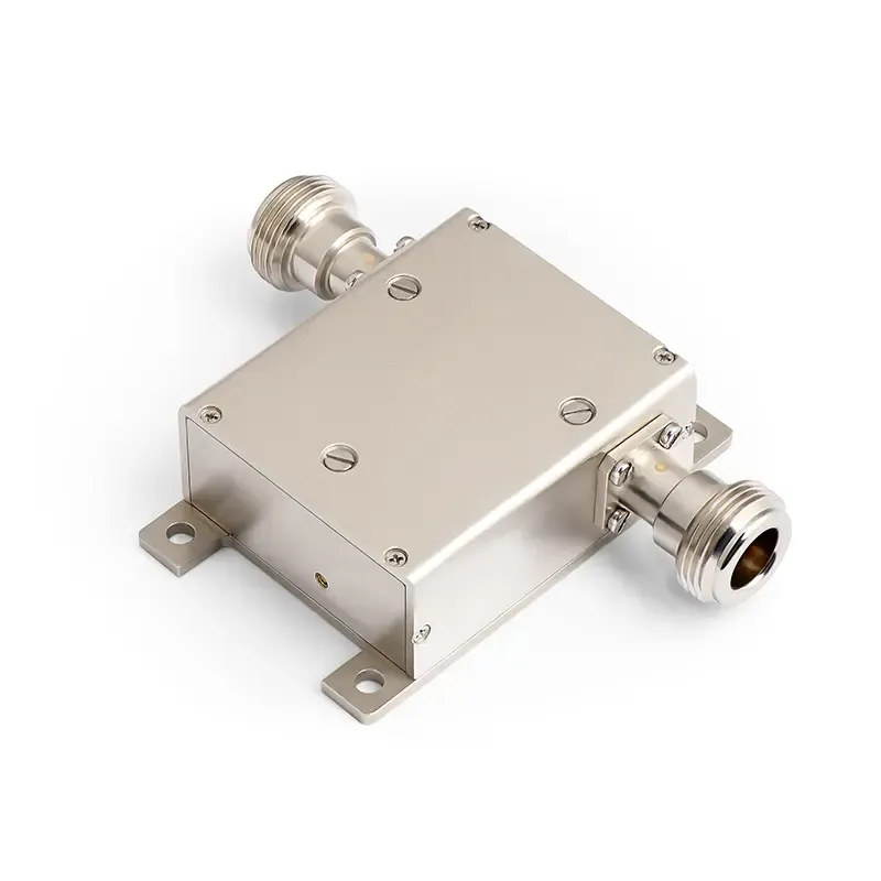
- Typical Coaxial Isolator is a fundamental component in RF and microwave systems, designed to provide efficient signal isolation and protection within a coaxial transmission line.
Key Features & Advantages
- Protects Equipment: Acts like a "shield" to prevent reflected signals from damaging expensive and sensitive transmission components (like power amplifiers).
- Stabilizes the System: Eliminates fluctuations and interference caused by reflected signals, making the system (e.g., base stations, radar) operate more stably.
- Low Loss: When the signal passes through in the forward direction, the energy loss is minimal.
- Compact & Easy to Integrate: Features a compact structure and standard interfaces, making it easy to embed into various circuits and modules.
Typical Applications
- Communication Systems: Cellular Base Stations (4G/5G), Microwave Relay/Backhaul Links, Satellite Communication
- Test & Measurement: Signal Source/Spectrum Analyzer Protection, Improved Measurement Accuracy
- Radar Systems
- RF Energy Applications: Medical Equipment, Industrial Heating/Plasma Generation
- General Electronic Systems: Frequency Source Modules, CATV Amplifiers
Electrical Performance Table and Product Appearance
0.1~0.4GHz Typical Coaxial Isolator
Product Overview
Here are commonly used products of Coaxial Isolators. This product covers the VHF to UHF band range
with a relative bandwidth of up to 10%. Dimensions, ports, and frequency bands can be customized based
on your requirements.
Model
Frequency(GHz)
BW Max
Insertion loss(dB) Max
Isolation(dB)Min
VSWR Max
Connector
operating temperature(℃)
PK/CW/RP(Watt)
Direction
HCITA01T04G⬇
0.1~0.4
10%
0.4
20
1.2
SMA
-55~+85℃
500/50/15
Clockwise
HCITB01T04G⬇
0.1~0.4
10%
0.4
20
1.2
SMA
-55~+85℃
500/50/15
Counter Clockwise
0.2~0.6GHz Typical Coaxial Isolator
Product Overview
Here are commonly used products of Coaxial Isolators. This product covers the VHF to UHF band range
with a relative bandwidth of up to 10%. Dimensions, ports, and frequency bands can be customized based
on your requirements.
Model
Frequency(GHz)
BW Max
Insertion loss(dB) Max
Isolation(dB)Min
VSWR Max
Connector
operating temperature(℃)
PK/CW/RP(Watt)
Direction
HCITA02T06G⬇
0.2~0.6
10%
0.4
20
1.2
SMA
-55~+85℃
500/50/15
Clockwise
HCITB02T06G⬇
0.2~0.6
10%
0.4
20
1.2
SMA
-55~+85℃
500/50/15
Counter Clockwise
0.4~1.0GHz Typical Coaxial Isolator
Product Overview
Here are commonly used products of Coaxial Isolators. This product covers the UHF band range with a
relative bandwidth of up to 10%. Dimensions, ports, and frequency bands can be customized based on your
requirements.
Model
Frequency(GHz)
BW Max
Insertion loss(dB) Max
Isolation(dB)Min
VSWR Max
Connector
operating temperature(℃)
PK/CW/RP(Watt)
Direction
HCITA04T10G⬇
0.4~1.0
10%
0.4
20
1.2
SMA
-55~+85℃
500/50/15
Clockwise
HCITB04T10G⬇
0.4~1.0
10%
0.4
20
1.2
SMA
-55~+85℃
500/50/15
Counter Clockwise
0.8~2.5GHz Typical Coaxial Isolator
Product Overview
Here are commonly used products of Coaxial Isolators. This product covers the UHF band range with a
relative bandwidth of up to 10%. Dimensions, ports, and frequency bands can be customized based on your
requirements.
Model
Frequency(GHz)
BW Max
Insertion loss(dB) Max
Isolation(dB)Min
VSWR Max
Connector
operating temperature(℃)
PK/CW/RP(Watt)
Direction
HCITA08T25G⬇
0.8~2.5
10%
0.4
20
1.2
SMA
-55~+85℃
500/50/15
Clockwise
HCITB08T25G⬇
0.8~2.5
10%
0.4
20
1.2
SMA
-55~+85℃
500/50/15
Counter Clockwise
1.5~3.5GHz Typical Coaxial Isolator
Product Overview
Here are commonly used products of Coaxial Isolators. This product covers the L~S band range with a
relative bandwidth of up to 10%. Dimensions, ports, and frequency bands can be customized based on your
requirements.
Model
Frequency(GHz)
BW Max
Insertion loss(dB) Max
Isolation(dB)Min
VSWR Max
Connector
operating temperature(℃)
PK/CW/RP(Watt)
Direction
HCITA15T35G⬇
1.5~3.5
10%
0.4
20
1.2
SMA
-55~+85℃
500/50/15
Clockwise
HCITB15T35G⬇
1.5~3.5
10%
0.4
20
1.2
SMA
-55~+85℃
500/50/15
Counter Clockwise
3.0~5.0GHz Typical Coaxial Isolator
Product Overview
Here are commonly used products of Coaxial Isolators. This product covers the S~C band range with a
relative bandwidth of up to 10%. Dimensions, ports, and frequency bands can be customized based on your
requirements.
Model
Frequency(GHz)
BW Max
Insertion loss(dB) Max
Isolation(dB)Min
VSWR Max
Connector
operating temperature(℃)
PK/CW/RP(Watt)
Direction
HCITA30T50G⬇
3.0~5.0
10%
0.4
20
1.2
SMA
-55~+85℃
200/40/15
Clockwise
HCITB30T50G⬇
3.0~5.0
10%
0.4
20
1.2
SMA
-55~+85℃
200/40/15
Counter Clockwise
4.0~8.0GHz Typical Coaxial Isolator
Product Overview
Here are commonly used products of Coaxial Isolators. This product covers the C- band range with a
relative bandwidth of up to 10%. Dimensions, ports, and frequency bands can be customized based on your
requirements.
Model
Frequency(GHz)
BW Max
Insertion loss(dB) Max
Isolation(dB)Min
VSWR Max
Connector
operating temperature(℃)
PK/CW/RP(Watt)
Direction
HCITA40T80G⬇
4.0~8.0
10%
0.4
20
1.2
SMA
-55~+85℃
400/40/15
Clockwise
HCITB40T80G⬇
4.0~8.0
10%
0.4
20
1.2
SMA
-55~+85℃
400/40/15
Counter Clockwise
8.0~19.0GHz Typical Coaxial Isolator
Product Overview
Here are commonly used products of Coaxial Isolators. This product covers the X Ku K- band range with a
relative bandwidth of up to 10%. Dimensions, ports, and frequency bands can be customized based on your
requirements.
Model
Frequency(GHz)
BW Max
Insertion loss(dB) Max
Isolation(dB)Min
VSWR Max
Connector
operating temperature(℃)
PK/CW/RP(Watt)
Direction
HCITA80T190G⬇
8.0~19.0
10%
0.4
20
1.25
SMA
-55~+85℃
200/40/15
Clockwise
HCITB80T190G⬇
8.0~19.0
10%
0.4
20
1.25
SMA
-55~+85℃
200/40/15
Counter Clockwise
20.0~25.0GHz Typical Coaxial Isolator
Product Overview
Here are commonly used products of Coaxial Isolators. This product covers the K- band range with a
relative bandwidth of up to 22.22%. Dimensions, ports, and frequency bands can be customized based on
your requirements.
Model
Frequency(GHz)
BW Max
Insertion loss(dB) Max
Isolation(dB)Min
VSWR Max
Connector
operating temperature(℃)
PK/CW/RP(Watt)
Direction
HCITA200T250G⬇
20.0~25.0
FULL
1.1
23
1.25
SMA
-55~+85℃
-/10/-
Clockwise
HCITB200T250G⬇
20.0~25.0
FULL
1.1
23
1.25
SMA
-55~+85℃
-/10/-
Counter Clockwise
18.0~40.0GHz Typical Coaxial Isolator
Product Overview
Here are commonly used products of Coaxial Isolators. This product covers the Ku K- band range with a
relative bandwidth of up to 10%. Dimensions, ports, and frequency bands can be customized based on your
requirements.
Model
Frequency(GHz)
BW Max
Insertion loss(dB) Max
Isolation(dB)Min
VSWR Max
Connector
operating temperature(℃)
PK/CW/RP(Watt)
Direction
HCITA180T400G⬇
18.0~40.0
10%
0.6
18
1.35
2.92
-55~+85℃
20/5/1
Clockwise
HCITB180T400G⬇
18.0~40.0
10%
0.6
18
1.35
2.92
-55~+85℃
20/5/1
Counter Clockwise
About HzBeat
HzBeat is a leading RF component manufacturer specializing in RF circulators and isolators, as a global supplier of RF circulators and isolators (20MHz–200GHz), we providing microstrip, drop-in, coaxial, and waveguide solutions for communication systems, radar, satellite, and medical imaging.
For detailed technical documentation, sample requests, or customization needs, please do not hesitate to contact us. — we respond within 24 hours to ensure you get precise solutions for your design.
Customization & Selection Guide
- Operating Band:Ensure it covers all frequencies required by your system.
- Power Handling Capacity:Select based on your system's transmit power (average and peak), allowing a certain margin.
- Performance Requirements:Define specific requirements for Insertion Loss, Isolation, and VSWR/Return Loss.
- Environmental Conditions:Consider operating temperature range, vibration, humidity, etc.
- Cost & Delivery:Balance cost and project timeline while meeting performance requirements.
Why Choose Our Product
- Profound Technical Expertise:We have over 18 years of R&D experience in ferrite materials and microwave magnetics.
- Fully Automated Production Lines:Ensure consistent excellence and reliability in every unit.
- Professional Application Support:Our engineering team provides timely technical selection, customization, and failure analysis services.
- Competitive Pricing & Lead Times:Economies of scale from mass production enable us to respond quickly to your orders.
Related Products
Questions? Feel Free to Reach Out Via Message.
Tell us frequency band, target IL/Isolation/VSWR, power level and timeline — we’ll match the best topology and deliver S-parameters.We will contact you within 24 hours.
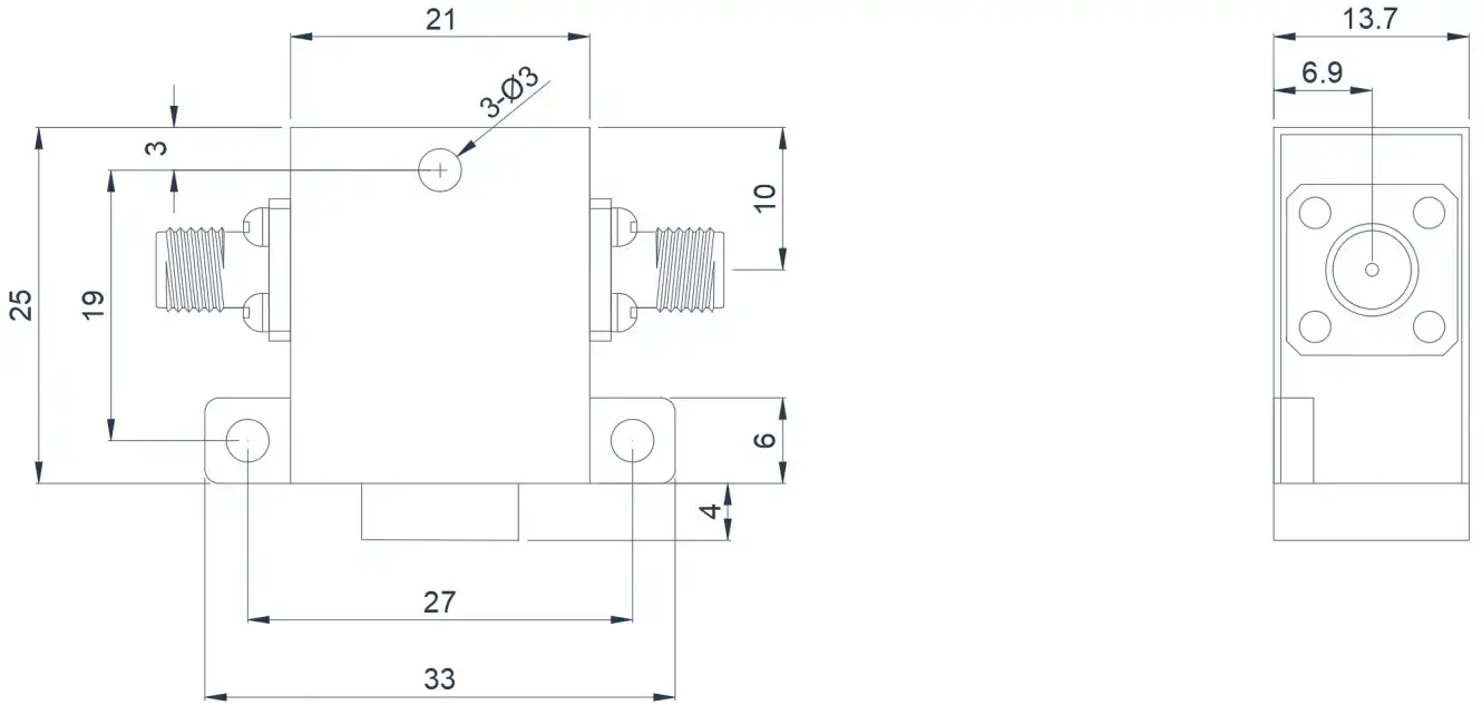
Product Overview
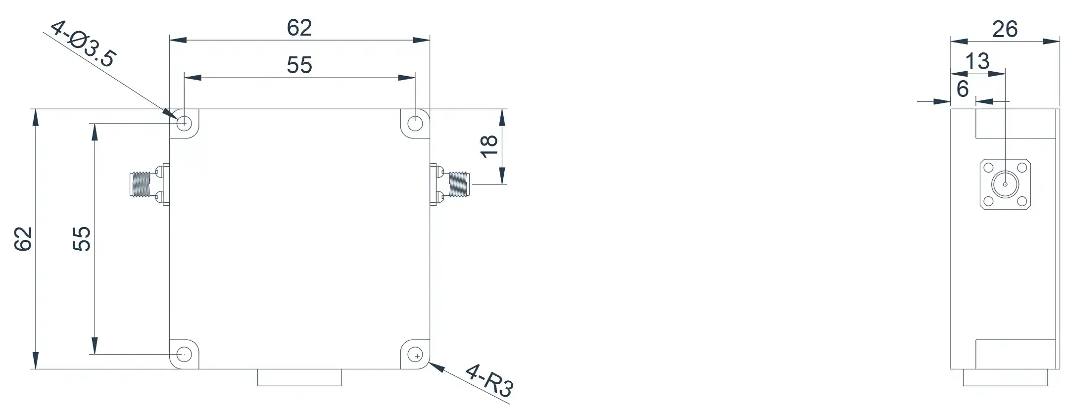
Here are commonly used products of Coaxial Isolators. This product covers the VHF to UHF band range with a relative bandwidth of up to 10%. Dimensions, ports, and frequency bands can be customized based on your requirements.
| Model | Frequency(GHz) | BW Max | Insertion loss(dB) Max | Isolation(dB)Min | VSWR Max | Connector | operating temperature(℃) | PK/CW/RP(Watt) | Direction |
|---|---|---|---|---|---|---|---|---|---|
| HCITA01T04G⬇ | 0.1~0.4 | 10% | 0.4 | 20 | 1.2 | SMA | -55~+85℃ | 500/50/15 | Clockwise |
| HCITB01T04G⬇ | 0.1~0.4 | 10% | 0.4 | 20 | 1.2 | SMA | -55~+85℃ | 500/50/15 | Counter Clockwise |
0.2~0.6GHz Typical Coaxial Isolator
Product Overview
Here are commonly used products of Coaxial Isolators. This product covers the VHF to UHF band range
with a relative bandwidth of up to 10%. Dimensions, ports, and frequency bands can be customized based
on your requirements.
Model
Frequency(GHz)
BW Max
Insertion loss(dB) Max
Isolation(dB)Min
VSWR Max
Connector
operating temperature(℃)
PK/CW/RP(Watt)
Direction
HCITA02T06G⬇
0.2~0.6
10%
0.4
20
1.2
SMA
-55~+85℃
500/50/15
Clockwise
HCITB02T06G⬇
0.2~0.6
10%
0.4
20
1.2
SMA
-55~+85℃
500/50/15
Counter Clockwise
0.4~1.0GHz Typical Coaxial Isolator
Product Overview
Here are commonly used products of Coaxial Isolators. This product covers the UHF band range with a
relative bandwidth of up to 10%. Dimensions, ports, and frequency bands can be customized based on your
requirements.
Model
Frequency(GHz)
BW Max
Insertion loss(dB) Max
Isolation(dB)Min
VSWR Max
Connector
operating temperature(℃)
PK/CW/RP(Watt)
Direction
HCITA04T10G⬇
0.4~1.0
10%
0.4
20
1.2
SMA
-55~+85℃
500/50/15
Clockwise
HCITB04T10G⬇
0.4~1.0
10%
0.4
20
1.2
SMA
-55~+85℃
500/50/15
Counter Clockwise
0.8~2.5GHz Typical Coaxial Isolator
Product Overview
Here are commonly used products of Coaxial Isolators. This product covers the UHF band range with a
relative bandwidth of up to 10%. Dimensions, ports, and frequency bands can be customized based on your
requirements.
Model
Frequency(GHz)
BW Max
Insertion loss(dB) Max
Isolation(dB)Min
VSWR Max
Connector
operating temperature(℃)
PK/CW/RP(Watt)
Direction
HCITA08T25G⬇
0.8~2.5
10%
0.4
20
1.2
SMA
-55~+85℃
500/50/15
Clockwise
HCITB08T25G⬇
0.8~2.5
10%
0.4
20
1.2
SMA
-55~+85℃
500/50/15
Counter Clockwise
1.5~3.5GHz Typical Coaxial Isolator
Product Overview
Here are commonly used products of Coaxial Isolators. This product covers the L~S band range with a
relative bandwidth of up to 10%. Dimensions, ports, and frequency bands can be customized based on your
requirements.
Model
Frequency(GHz)
BW Max
Insertion loss(dB) Max
Isolation(dB)Min
VSWR Max
Connector
operating temperature(℃)
PK/CW/RP(Watt)
Direction
HCITA15T35G⬇
1.5~3.5
10%
0.4
20
1.2
SMA
-55~+85℃
500/50/15
Clockwise
HCITB15T35G⬇
1.5~3.5
10%
0.4
20
1.2
SMA
-55~+85℃
500/50/15
Counter Clockwise
3.0~5.0GHz Typical Coaxial Isolator
Product Overview
Here are commonly used products of Coaxial Isolators. This product covers the S~C band range with a
relative bandwidth of up to 10%. Dimensions, ports, and frequency bands can be customized based on your
requirements.
Model
Frequency(GHz)
BW Max
Insertion loss(dB) Max
Isolation(dB)Min
VSWR Max
Connector
operating temperature(℃)
PK/CW/RP(Watt)
Direction
HCITA30T50G⬇
3.0~5.0
10%
0.4
20
1.2
SMA
-55~+85℃
200/40/15
Clockwise
HCITB30T50G⬇
3.0~5.0
10%
0.4
20
1.2
SMA
-55~+85℃
200/40/15
Counter Clockwise
4.0~8.0GHz Typical Coaxial Isolator
Product Overview
Here are commonly used products of Coaxial Isolators. This product covers the C- band range with a
relative bandwidth of up to 10%. Dimensions, ports, and frequency bands can be customized based on your
requirements.
Model
Frequency(GHz)
BW Max
Insertion loss(dB) Max
Isolation(dB)Min
VSWR Max
Connector
operating temperature(℃)
PK/CW/RP(Watt)
Direction
HCITA40T80G⬇
4.0~8.0
10%
0.4
20
1.2
SMA
-55~+85℃
400/40/15
Clockwise
HCITB40T80G⬇
4.0~8.0
10%
0.4
20
1.2
SMA
-55~+85℃
400/40/15
Counter Clockwise
8.0~19.0GHz Typical Coaxial Isolator
Product Overview
Here are commonly used products of Coaxial Isolators. This product covers the X Ku K- band range with a
relative bandwidth of up to 10%. Dimensions, ports, and frequency bands can be customized based on your
requirements.
Model
Frequency(GHz)
BW Max
Insertion loss(dB) Max
Isolation(dB)Min
VSWR Max
Connector
operating temperature(℃)
PK/CW/RP(Watt)
Direction
HCITA80T190G⬇
8.0~19.0
10%
0.4
20
1.25
SMA
-55~+85℃
200/40/15
Clockwise
HCITB80T190G⬇
8.0~19.0
10%
0.4
20
1.25
SMA
-55~+85℃
200/40/15
Counter Clockwise
20.0~25.0GHz Typical Coaxial Isolator
Product Overview
Here are commonly used products of Coaxial Isolators. This product covers the K- band range with a
relative bandwidth of up to 22.22%. Dimensions, ports, and frequency bands can be customized based on
your requirements.
Model
Frequency(GHz)
BW Max
Insertion loss(dB) Max
Isolation(dB)Min
VSWR Max
Connector
operating temperature(℃)
PK/CW/RP(Watt)
Direction
HCITA200T250G⬇
20.0~25.0
FULL
1.1
23
1.25
SMA
-55~+85℃
-/10/-
Clockwise
HCITB200T250G⬇
20.0~25.0
FULL
1.1
23
1.25
SMA
-55~+85℃
-/10/-
Counter Clockwise
18.0~40.0GHz Typical Coaxial Isolator
Product Overview
Here are commonly used products of Coaxial Isolators. This product covers the Ku K- band range with a
relative bandwidth of up to 10%. Dimensions, ports, and frequency bands can be customized based on your
requirements.
Model
Frequency(GHz)
BW Max
Insertion loss(dB) Max
Isolation(dB)Min
VSWR Max
Connector
operating temperature(℃)
PK/CW/RP(Watt)
Direction
HCITA180T400G⬇
18.0~40.0
10%
0.6
18
1.35
2.92
-55~+85℃
20/5/1
Clockwise
HCITB180T400G⬇
18.0~40.0
10%
0.6
18
1.35
2.92
-55~+85℃
20/5/1
Counter Clockwise
About HzBeat
HzBeat is a leading RF component manufacturer specializing in RF circulators and isolators, as a global supplier of RF circulators and isolators (20MHz–200GHz), we providing microstrip, drop-in, coaxial, and waveguide solutions for communication systems, radar, satellite, and medical imaging.
For detailed technical documentation, sample requests, or customization needs, please do not hesitate to contact us. — we respond within 24 hours to ensure you get precise solutions for your design.
Customization & Selection Guide
- Operating Band:Ensure it covers all frequencies required by your system.
- Power Handling Capacity:Select based on your system's transmit power (average and peak), allowing a certain margin.
- Performance Requirements:Define specific requirements for Insertion Loss, Isolation, and VSWR/Return Loss.
- Environmental Conditions:Consider operating temperature range, vibration, humidity, etc.
- Cost & Delivery:Balance cost and project timeline while meeting performance requirements.
Why Choose Our Product
- Profound Technical Expertise:We have over 18 years of R&D experience in ferrite materials and microwave magnetics.
- Fully Automated Production Lines:Ensure consistent excellence and reliability in every unit.
- Professional Application Support:Our engineering team provides timely technical selection, customization, and failure analysis services.
- Competitive Pricing & Lead Times:Economies of scale from mass production enable us to respond quickly to your orders.
Related Products
Questions? Feel Free to Reach Out Via Message.
Tell us frequency band, target IL/Isolation/VSWR, power level and timeline — we’ll match the best topology and deliver S-parameters.We will contact you within 24 hours.
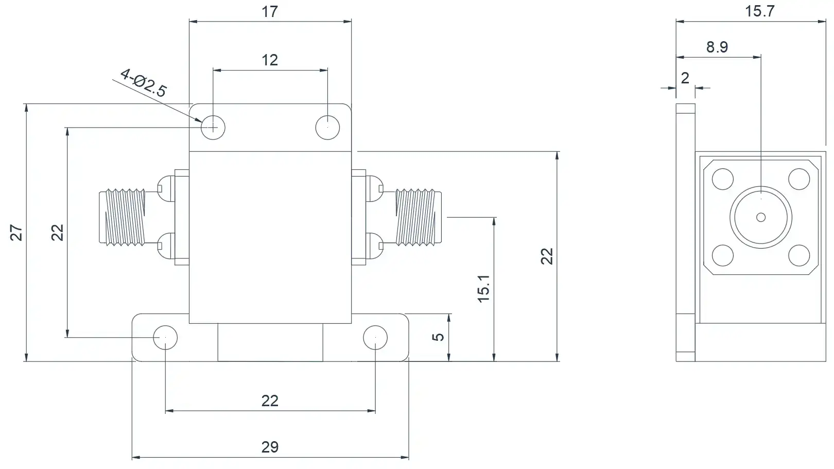
Product Overview
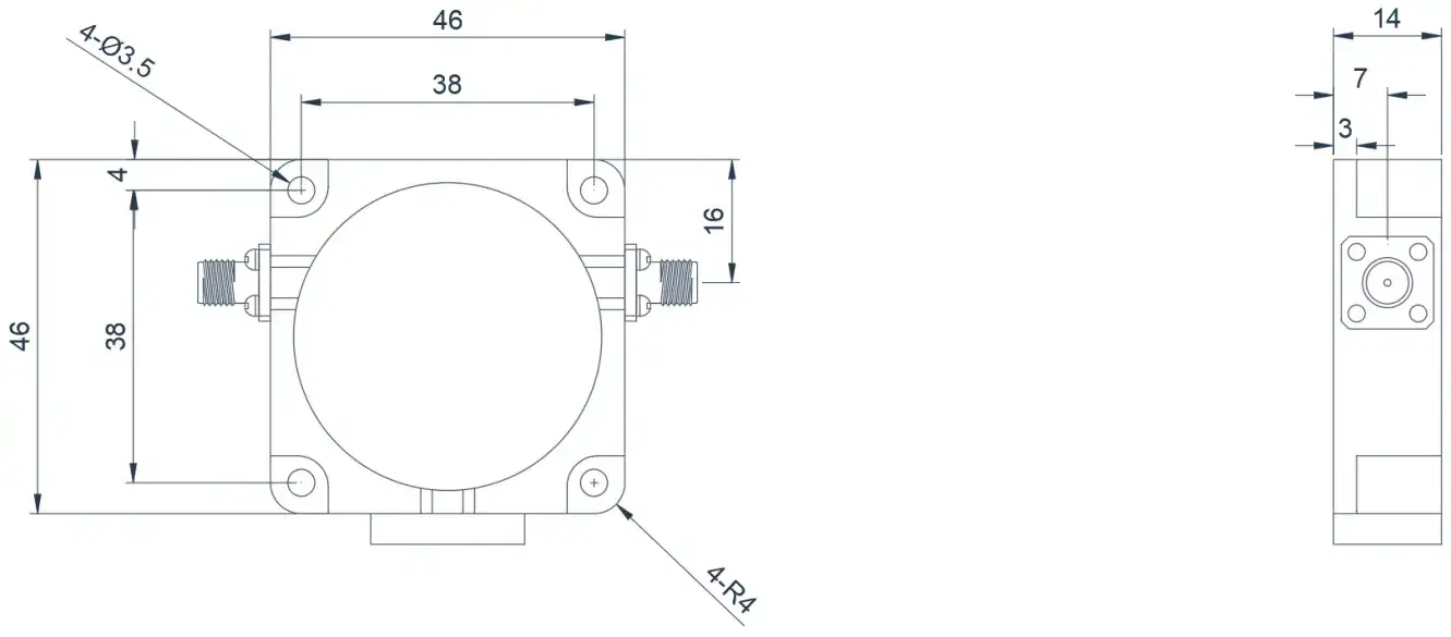
Here are commonly used products of Coaxial Isolators. This product covers the VHF to UHF band range with a relative bandwidth of up to 10%. Dimensions, ports, and frequency bands can be customized based on your requirements.
| Model | Frequency(GHz) | BW Max | Insertion loss(dB) Max | Isolation(dB)Min | VSWR Max | Connector | operating temperature(℃) | PK/CW/RP(Watt) | Direction |
|---|---|---|---|---|---|---|---|---|---|
| HCITA02T06G⬇ | 0.2~0.6 | 10% | 0.4 | 20 | 1.2 | SMA | -55~+85℃ | 500/50/15 | Clockwise |
| HCITB02T06G⬇ | 0.2~0.6 | 10% | 0.4 | 20 | 1.2 | SMA | -55~+85℃ | 500/50/15 | Counter Clockwise |
0.4~1.0GHz Typical Coaxial Isolator
Product Overview
Here are commonly used products of Coaxial Isolators. This product covers the UHF band range with a
relative bandwidth of up to 10%. Dimensions, ports, and frequency bands can be customized based on your
requirements.
Model
Frequency(GHz)
BW Max
Insertion loss(dB) Max
Isolation(dB)Min
VSWR Max
Connector
operating temperature(℃)
PK/CW/RP(Watt)
Direction
HCITA04T10G⬇
0.4~1.0
10%
0.4
20
1.2
SMA
-55~+85℃
500/50/15
Clockwise
HCITB04T10G⬇
0.4~1.0
10%
0.4
20
1.2
SMA
-55~+85℃
500/50/15
Counter Clockwise
0.8~2.5GHz Typical Coaxial Isolator
Product Overview
Here are commonly used products of Coaxial Isolators. This product covers the UHF band range with a
relative bandwidth of up to 10%. Dimensions, ports, and frequency bands can be customized based on your
requirements.
Model
Frequency(GHz)
BW Max
Insertion loss(dB) Max
Isolation(dB)Min
VSWR Max
Connector
operating temperature(℃)
PK/CW/RP(Watt)
Direction
HCITA08T25G⬇
0.8~2.5
10%
0.4
20
1.2
SMA
-55~+85℃
500/50/15
Clockwise
HCITB08T25G⬇
0.8~2.5
10%
0.4
20
1.2
SMA
-55~+85℃
500/50/15
Counter Clockwise
1.5~3.5GHz Typical Coaxial Isolator
Product Overview
Here are commonly used products of Coaxial Isolators. This product covers the L~S band range with a
relative bandwidth of up to 10%. Dimensions, ports, and frequency bands can be customized based on your
requirements.
Model
Frequency(GHz)
BW Max
Insertion loss(dB) Max
Isolation(dB)Min
VSWR Max
Connector
operating temperature(℃)
PK/CW/RP(Watt)
Direction
HCITA15T35G⬇
1.5~3.5
10%
0.4
20
1.2
SMA
-55~+85℃
500/50/15
Clockwise
HCITB15T35G⬇
1.5~3.5
10%
0.4
20
1.2
SMA
-55~+85℃
500/50/15
Counter Clockwise
3.0~5.0GHz Typical Coaxial Isolator
Product Overview
Here are commonly used products of Coaxial Isolators. This product covers the S~C band range with a
relative bandwidth of up to 10%. Dimensions, ports, and frequency bands can be customized based on your
requirements.
Model
Frequency(GHz)
BW Max
Insertion loss(dB) Max
Isolation(dB)Min
VSWR Max
Connector
operating temperature(℃)
PK/CW/RP(Watt)
Direction
HCITA30T50G⬇
3.0~5.0
10%
0.4
20
1.2
SMA
-55~+85℃
200/40/15
Clockwise
HCITB30T50G⬇
3.0~5.0
10%
0.4
20
1.2
SMA
-55~+85℃
200/40/15
Counter Clockwise
4.0~8.0GHz Typical Coaxial Isolator
Product Overview
Here are commonly used products of Coaxial Isolators. This product covers the C- band range with a
relative bandwidth of up to 10%. Dimensions, ports, and frequency bands can be customized based on your
requirements.
Model
Frequency(GHz)
BW Max
Insertion loss(dB) Max
Isolation(dB)Min
VSWR Max
Connector
operating temperature(℃)
PK/CW/RP(Watt)
Direction
HCITA40T80G⬇
4.0~8.0
10%
0.4
20
1.2
SMA
-55~+85℃
400/40/15
Clockwise
HCITB40T80G⬇
4.0~8.0
10%
0.4
20
1.2
SMA
-55~+85℃
400/40/15
Counter Clockwise
8.0~19.0GHz Typical Coaxial Isolator
Product Overview
Here are commonly used products of Coaxial Isolators. This product covers the X Ku K- band range with a
relative bandwidth of up to 10%. Dimensions, ports, and frequency bands can be customized based on your
requirements.
Model
Frequency(GHz)
BW Max
Insertion loss(dB) Max
Isolation(dB)Min
VSWR Max
Connector
operating temperature(℃)
PK/CW/RP(Watt)
Direction
HCITA80T190G⬇
8.0~19.0
10%
0.4
20
1.25
SMA
-55~+85℃
200/40/15
Clockwise
HCITB80T190G⬇
8.0~19.0
10%
0.4
20
1.25
SMA
-55~+85℃
200/40/15
Counter Clockwise
20.0~25.0GHz Typical Coaxial Isolator
Product Overview
Here are commonly used products of Coaxial Isolators. This product covers the K- band range with a
relative bandwidth of up to 22.22%. Dimensions, ports, and frequency bands can be customized based on
your requirements.
Model
Frequency(GHz)
BW Max
Insertion loss(dB) Max
Isolation(dB)Min
VSWR Max
Connector
operating temperature(℃)
PK/CW/RP(Watt)
Direction
HCITA200T250G⬇
20.0~25.0
FULL
1.1
23
1.25
SMA
-55~+85℃
-/10/-
Clockwise
HCITB200T250G⬇
20.0~25.0
FULL
1.1
23
1.25
SMA
-55~+85℃
-/10/-
Counter Clockwise
18.0~40.0GHz Typical Coaxial Isolator
Product Overview
Here are commonly used products of Coaxial Isolators. This product covers the Ku K- band range with a
relative bandwidth of up to 10%. Dimensions, ports, and frequency bands can be customized based on your
requirements.
Model
Frequency(GHz)
BW Max
Insertion loss(dB) Max
Isolation(dB)Min
VSWR Max
Connector
operating temperature(℃)
PK/CW/RP(Watt)
Direction
HCITA180T400G⬇
18.0~40.0
10%
0.6
18
1.35
2.92
-55~+85℃
20/5/1
Clockwise
HCITB180T400G⬇
18.0~40.0
10%
0.6
18
1.35
2.92
-55~+85℃
20/5/1
Counter Clockwise
About HzBeat
HzBeat is a leading RF component manufacturer specializing in RF circulators and isolators, as a global supplier of RF circulators and isolators (20MHz–200GHz), we providing microstrip, drop-in, coaxial, and waveguide solutions for communication systems, radar, satellite, and medical imaging.
For detailed technical documentation, sample requests, or customization needs, please do not hesitate to contact us. — we respond within 24 hours to ensure you get precise solutions for your design.
Customization & Selection Guide
- Operating Band:Ensure it covers all frequencies required by your system.
- Power Handling Capacity:Select based on your system's transmit power (average and peak), allowing a certain margin.
- Performance Requirements:Define specific requirements for Insertion Loss, Isolation, and VSWR/Return Loss.
- Environmental Conditions:Consider operating temperature range, vibration, humidity, etc.
- Cost & Delivery:Balance cost and project timeline while meeting performance requirements.
Why Choose Our Product
- Profound Technical Expertise:We have over 18 years of R&D experience in ferrite materials and microwave magnetics.
- Fully Automated Production Lines:Ensure consistent excellence and reliability in every unit.
- Professional Application Support:Our engineering team provides timely technical selection, customization, and failure analysis services.
- Competitive Pricing & Lead Times:Economies of scale from mass production enable us to respond quickly to your orders.
Related Products
Questions? Feel Free to Reach Out Via Message.
Tell us frequency band, target IL/Isolation/VSWR, power level and timeline — we’ll match the best topology and deliver S-parameters.We will contact you within 24 hours.
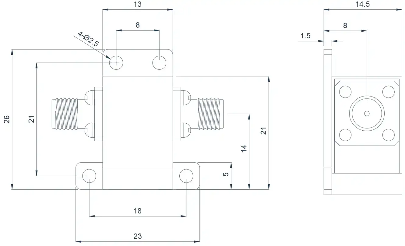
Product Overview
Here are commonly used products of Coaxial Isolators. This product covers the UHF band range with a relative bandwidth of up to 10%. Dimensions, ports, and frequency bands can be customized based on your requirements.
| Model | Frequency(GHz) | BW Max | Insertion loss(dB) Max | Isolation(dB)Min | VSWR Max | Connector | operating temperature(℃) | PK/CW/RP(Watt) | Direction |
|---|---|---|---|---|---|---|---|---|---|
| HCITA04T10G⬇ | 0.4~1.0 | 10% | 0.4 | 20 | 1.2 | SMA | -55~+85℃ | 500/50/15 | Clockwise |
| HCITB04T10G⬇ | 0.4~1.0 | 10% | 0.4 | 20 | 1.2 | SMA | -55~+85℃ | 500/50/15 | Counter Clockwise |
0.8~2.5GHz Typical Coaxial Isolator
Product Overview
Here are commonly used products of Coaxial Isolators. This product covers the UHF band range with a
relative bandwidth of up to 10%. Dimensions, ports, and frequency bands can be customized based on your
requirements.
Model
Frequency(GHz)
BW Max
Insertion loss(dB) Max
Isolation(dB)Min
VSWR Max
Connector
operating temperature(℃)
PK/CW/RP(Watt)
Direction
HCITA08T25G⬇
0.8~2.5
10%
0.4
20
1.2
SMA
-55~+85℃
500/50/15
Clockwise
HCITB08T25G⬇
0.8~2.5
10%
0.4
20
1.2
SMA
-55~+85℃
500/50/15
Counter Clockwise
1.5~3.5GHz Typical Coaxial Isolator
Product Overview
Here are commonly used products of Coaxial Isolators. This product covers the L~S band range with a
relative bandwidth of up to 10%. Dimensions, ports, and frequency bands can be customized based on your
requirements.
Model
Frequency(GHz)
BW Max
Insertion loss(dB) Max
Isolation(dB)Min
VSWR Max
Connector
operating temperature(℃)
PK/CW/RP(Watt)
Direction
HCITA15T35G⬇
1.5~3.5
10%
0.4
20
1.2
SMA
-55~+85℃
500/50/15
Clockwise
HCITB15T35G⬇
1.5~3.5
10%
0.4
20
1.2
SMA
-55~+85℃
500/50/15
Counter Clockwise
3.0~5.0GHz Typical Coaxial Isolator
Product Overview
Here are commonly used products of Coaxial Isolators. This product covers the S~C band range with a
relative bandwidth of up to 10%. Dimensions, ports, and frequency bands can be customized based on your
requirements.
Model
Frequency(GHz)
BW Max
Insertion loss(dB) Max
Isolation(dB)Min
VSWR Max
Connector
operating temperature(℃)
PK/CW/RP(Watt)
Direction
HCITA30T50G⬇
3.0~5.0
10%
0.4
20
1.2
SMA
-55~+85℃
200/40/15
Clockwise
HCITB30T50G⬇
3.0~5.0
10%
0.4
20
1.2
SMA
-55~+85℃
200/40/15
Counter Clockwise
4.0~8.0GHz Typical Coaxial Isolator
Product Overview
Here are commonly used products of Coaxial Isolators. This product covers the C- band range with a
relative bandwidth of up to 10%. Dimensions, ports, and frequency bands can be customized based on your
requirements.
Model
Frequency(GHz)
BW Max
Insertion loss(dB) Max
Isolation(dB)Min
VSWR Max
Connector
operating temperature(℃)
PK/CW/RP(Watt)
Direction
HCITA40T80G⬇
4.0~8.0
10%
0.4
20
1.2
SMA
-55~+85℃
400/40/15
Clockwise
HCITB40T80G⬇
4.0~8.0
10%
0.4
20
1.2
SMA
-55~+85℃
400/40/15
Counter Clockwise
8.0~19.0GHz Typical Coaxial Isolator
Product Overview
Here are commonly used products of Coaxial Isolators. This product covers the X Ku K- band range with a
relative bandwidth of up to 10%. Dimensions, ports, and frequency bands can be customized based on your
requirements.
Model
Frequency(GHz)
BW Max
Insertion loss(dB) Max
Isolation(dB)Min
VSWR Max
Connector
operating temperature(℃)
PK/CW/RP(Watt)
Direction
HCITA80T190G⬇
8.0~19.0
10%
0.4
20
1.25
SMA
-55~+85℃
200/40/15
Clockwise
HCITB80T190G⬇
8.0~19.0
10%
0.4
20
1.25
SMA
-55~+85℃
200/40/15
Counter Clockwise
20.0~25.0GHz Typical Coaxial Isolator
Product Overview
Here are commonly used products of Coaxial Isolators. This product covers the K- band range with a
relative bandwidth of up to 22.22%. Dimensions, ports, and frequency bands can be customized based on
your requirements.
Model
Frequency(GHz)
BW Max
Insertion loss(dB) Max
Isolation(dB)Min
VSWR Max
Connector
operating temperature(℃)
PK/CW/RP(Watt)
Direction
HCITA200T250G⬇
20.0~25.0
FULL
1.1
23
1.25
SMA
-55~+85℃
-/10/-
Clockwise
HCITB200T250G⬇
20.0~25.0
FULL
1.1
23
1.25
SMA
-55~+85℃
-/10/-
Counter Clockwise
18.0~40.0GHz Typical Coaxial Isolator
Product Overview
Here are commonly used products of Coaxial Isolators. This product covers the Ku K- band range with a
relative bandwidth of up to 10%. Dimensions, ports, and frequency bands can be customized based on your
requirements.
Model
Frequency(GHz)
BW Max
Insertion loss(dB) Max
Isolation(dB)Min
VSWR Max
Connector
operating temperature(℃)
PK/CW/RP(Watt)
Direction
HCITA180T400G⬇
18.0~40.0
10%
0.6
18
1.35
2.92
-55~+85℃
20/5/1
Clockwise
HCITB180T400G⬇
18.0~40.0
10%
0.6
18
1.35
2.92
-55~+85℃
20/5/1
Counter Clockwise
About HzBeat
HzBeat is a leading RF component manufacturer specializing in RF circulators and isolators, as a global supplier of RF circulators and isolators (20MHz–200GHz), we providing microstrip, drop-in, coaxial, and waveguide solutions for communication systems, radar, satellite, and medical imaging.
For detailed technical documentation, sample requests, or customization needs, please do not hesitate to contact us. — we respond within 24 hours to ensure you get precise solutions for your design.
Customization & Selection Guide
- Operating Band:Ensure it covers all frequencies required by your system.
- Power Handling Capacity:Select based on your system's transmit power (average and peak), allowing a certain margin.
- Performance Requirements:Define specific requirements for Insertion Loss, Isolation, and VSWR/Return Loss.
- Environmental Conditions:Consider operating temperature range, vibration, humidity, etc.
- Cost & Delivery:Balance cost and project timeline while meeting performance requirements.
Why Choose Our Product
- Profound Technical Expertise:We have over 18 years of R&D experience in ferrite materials and microwave magnetics.
- Fully Automated Production Lines:Ensure consistent excellence and reliability in every unit.
- Professional Application Support:Our engineering team provides timely technical selection, customization, and failure analysis services.
- Competitive Pricing & Lead Times:Economies of scale from mass production enable us to respond quickly to your orders.
Related Products
Questions? Feel Free to Reach Out Via Message.
Tell us frequency band, target IL/Isolation/VSWR, power level and timeline — we’ll match the best topology and deliver S-parameters.We will contact you within 24 hours.
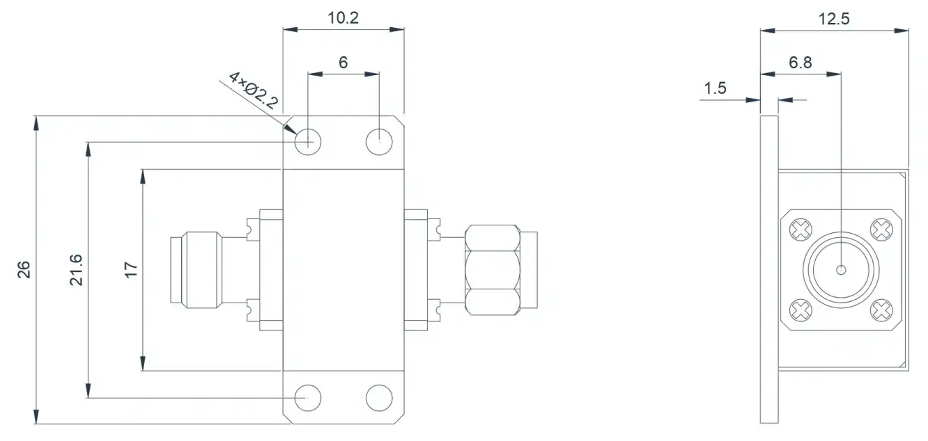
Product Overview
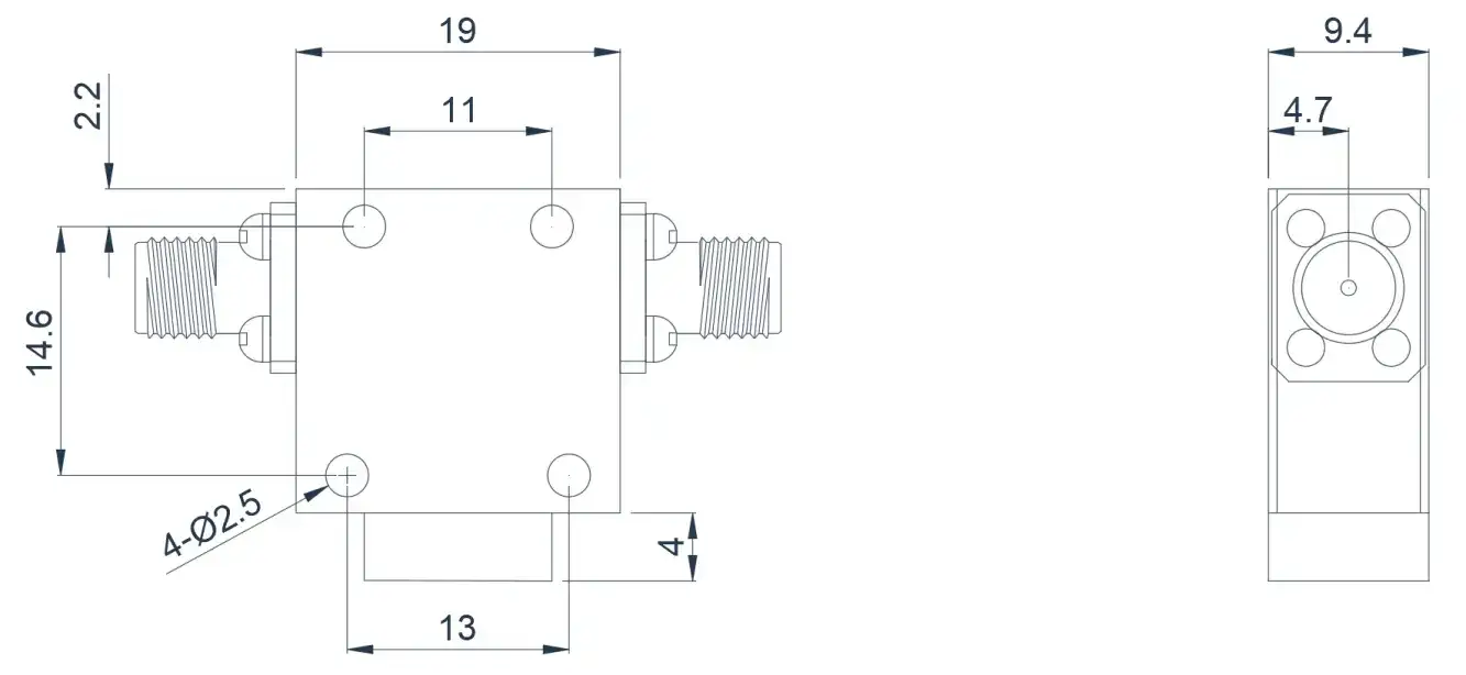
Here are commonly used products of Coaxial Isolators. This product covers the UHF band range with a relative bandwidth of up to 10%. Dimensions, ports, and frequency bands can be customized based on your requirements.
| Model | Frequency(GHz) | BW Max | Insertion loss(dB) Max | Isolation(dB)Min | VSWR Max | Connector | operating temperature(℃) | PK/CW/RP(Watt) | Direction |
|---|---|---|---|---|---|---|---|---|---|
| HCITA08T25G⬇ | 0.8~2.5 | 10% | 0.4 | 20 | 1.2 | SMA | -55~+85℃ | 500/50/15 | Clockwise |
| HCITB08T25G⬇ | 0.8~2.5 | 10% | 0.4 | 20 | 1.2 | SMA | -55~+85℃ | 500/50/15 | Counter Clockwise |
1.5~3.5GHz Typical Coaxial Isolator
Product Overview
Here are commonly used products of Coaxial Isolators. This product covers the L~S band range with a
relative bandwidth of up to 10%. Dimensions, ports, and frequency bands can be customized based on your
requirements.
Model
Frequency(GHz)
BW Max
Insertion loss(dB) Max
Isolation(dB)Min
VSWR Max
Connector
operating temperature(℃)
PK/CW/RP(Watt)
Direction
HCITA15T35G⬇
1.5~3.5
10%
0.4
20
1.2
SMA
-55~+85℃
500/50/15
Clockwise
HCITB15T35G⬇
1.5~3.5
10%
0.4
20
1.2
SMA
-55~+85℃
500/50/15
Counter Clockwise
3.0~5.0GHz Typical Coaxial Isolator
Product Overview
Here are commonly used products of Coaxial Isolators. This product covers the S~C band range with a
relative bandwidth of up to 10%. Dimensions, ports, and frequency bands can be customized based on your
requirements.
Model
Frequency(GHz)
BW Max
Insertion loss(dB) Max
Isolation(dB)Min
VSWR Max
Connector
operating temperature(℃)
PK/CW/RP(Watt)
Direction
HCITA30T50G⬇
3.0~5.0
10%
0.4
20
1.2
SMA
-55~+85℃
200/40/15
Clockwise
HCITB30T50G⬇
3.0~5.0
10%
0.4
20
1.2
SMA
-55~+85℃
200/40/15
Counter Clockwise
4.0~8.0GHz Typical Coaxial Isolator
Product Overview
Here are commonly used products of Coaxial Isolators. This product covers the C- band range with a
relative bandwidth of up to 10%. Dimensions, ports, and frequency bands can be customized based on your
requirements.
Model
Frequency(GHz)
BW Max
Insertion loss(dB) Max
Isolation(dB)Min
VSWR Max
Connector
operating temperature(℃)
PK/CW/RP(Watt)
Direction
HCITA40T80G⬇
4.0~8.0
10%
0.4
20
1.2
SMA
-55~+85℃
400/40/15
Clockwise
HCITB40T80G⬇
4.0~8.0
10%
0.4
20
1.2
SMA
-55~+85℃
400/40/15
Counter Clockwise
8.0~19.0GHz Typical Coaxial Isolator
Product Overview
Here are commonly used products of Coaxial Isolators. This product covers the X Ku K- band range with a
relative bandwidth of up to 10%. Dimensions, ports, and frequency bands can be customized based on your
requirements.
Model
Frequency(GHz)
BW Max
Insertion loss(dB) Max
Isolation(dB)Min
VSWR Max
Connector
operating temperature(℃)
PK/CW/RP(Watt)
Direction
HCITA80T190G⬇
8.0~19.0
10%
0.4
20
1.25
SMA
-55~+85℃
200/40/15
Clockwise
HCITB80T190G⬇
8.0~19.0
10%
0.4
20
1.25
SMA
-55~+85℃
200/40/15
Counter Clockwise
20.0~25.0GHz Typical Coaxial Isolator
Product Overview
Here are commonly used products of Coaxial Isolators. This product covers the K- band range with a
relative bandwidth of up to 22.22%. Dimensions, ports, and frequency bands can be customized based on
your requirements.
Model
Frequency(GHz)
BW Max
Insertion loss(dB) Max
Isolation(dB)Min
VSWR Max
Connector
operating temperature(℃)
PK/CW/RP(Watt)
Direction
HCITA200T250G⬇
20.0~25.0
FULL
1.1
23
1.25
SMA
-55~+85℃
-/10/-
Clockwise
HCITB200T250G⬇
20.0~25.0
FULL
1.1
23
1.25
SMA
-55~+85℃
-/10/-
Counter Clockwise
18.0~40.0GHz Typical Coaxial Isolator
Product Overview
Here are commonly used products of Coaxial Isolators. This product covers the Ku K- band range with a
relative bandwidth of up to 10%. Dimensions, ports, and frequency bands can be customized based on your
requirements.
Model
Frequency(GHz)
BW Max
Insertion loss(dB) Max
Isolation(dB)Min
VSWR Max
Connector
operating temperature(℃)
PK/CW/RP(Watt)
Direction
HCITA180T400G⬇
18.0~40.0
10%
0.6
18
1.35
2.92
-55~+85℃
20/5/1
Clockwise
HCITB180T400G⬇
18.0~40.0
10%
0.6
18
1.35
2.92
-55~+85℃
20/5/1
Counter Clockwise
About HzBeat
HzBeat is a leading RF component manufacturer specializing in RF circulators and isolators, as a global supplier of RF circulators and isolators (20MHz–200GHz), we providing microstrip, drop-in, coaxial, and waveguide solutions for communication systems, radar, satellite, and medical imaging.
For detailed technical documentation, sample requests, or customization needs, please do not hesitate to contact us. — we respond within 24 hours to ensure you get precise solutions for your design.
Customization & Selection Guide
- Operating Band:Ensure it covers all frequencies required by your system.
- Power Handling Capacity:Select based on your system's transmit power (average and peak), allowing a certain margin.
- Performance Requirements:Define specific requirements for Insertion Loss, Isolation, and VSWR/Return Loss.
- Environmental Conditions:Consider operating temperature range, vibration, humidity, etc.
- Cost & Delivery:Balance cost and project timeline while meeting performance requirements.
Why Choose Our Product
- Profound Technical Expertise:We have over 18 years of R&D experience in ferrite materials and microwave magnetics.
- Fully Automated Production Lines:Ensure consistent excellence and reliability in every unit.
- Professional Application Support:Our engineering team provides timely technical selection, customization, and failure analysis services.
- Competitive Pricing & Lead Times:Economies of scale from mass production enable us to respond quickly to your orders.
Related Products
Questions? Feel Free to Reach Out Via Message.
Tell us frequency band, target IL/Isolation/VSWR, power level and timeline — we’ll match the best topology and deliver S-parameters.We will contact you within 24 hours.
Product Overview
Here are commonly used products of Coaxial Isolators. This product covers the L~S band range with a relative bandwidth of up to 10%. Dimensions, ports, and frequency bands can be customized based on your requirements.
| Model | Frequency(GHz) | BW Max | Insertion loss(dB) Max | Isolation(dB)Min | VSWR Max | Connector | operating temperature(℃) | PK/CW/RP(Watt) | Direction |
|---|---|---|---|---|---|---|---|---|---|
| HCITA15T35G⬇ | 1.5~3.5 | 10% | 0.4 | 20 | 1.2 | SMA | -55~+85℃ | 500/50/15 | Clockwise |
| HCITB15T35G⬇ | 1.5~3.5 | 10% | 0.4 | 20 | 1.2 | SMA | -55~+85℃ | 500/50/15 | Counter Clockwise |
3.0~5.0GHz Typical Coaxial Isolator
Product Overview
Here are commonly used products of Coaxial Isolators. This product covers the S~C band range with a
relative bandwidth of up to 10%. Dimensions, ports, and frequency bands can be customized based on your
requirements.
Model
Frequency(GHz)
BW Max
Insertion loss(dB) Max
Isolation(dB)Min
VSWR Max
Connector
operating temperature(℃)
PK/CW/RP(Watt)
Direction
HCITA30T50G⬇
3.0~5.0
10%
0.4
20
1.2
SMA
-55~+85℃
200/40/15
Clockwise
HCITB30T50G⬇
3.0~5.0
10%
0.4
20
1.2
SMA
-55~+85℃
200/40/15
Counter Clockwise
4.0~8.0GHz Typical Coaxial Isolator
Product Overview
Here are commonly used products of Coaxial Isolators. This product covers the C- band range with a
relative bandwidth of up to 10%. Dimensions, ports, and frequency bands can be customized based on your
requirements.
Model
Frequency(GHz)
BW Max
Insertion loss(dB) Max
Isolation(dB)Min
VSWR Max
Connector
operating temperature(℃)
PK/CW/RP(Watt)
Direction
HCITA40T80G⬇
4.0~8.0
10%
0.4
20
1.2
SMA
-55~+85℃
400/40/15
Clockwise
HCITB40T80G⬇
4.0~8.0
10%
0.4
20
1.2
SMA
-55~+85℃
400/40/15
Counter Clockwise
8.0~19.0GHz Typical Coaxial Isolator
Product Overview
Here are commonly used products of Coaxial Isolators. This product covers the X Ku K- band range with a
relative bandwidth of up to 10%. Dimensions, ports, and frequency bands can be customized based on your
requirements.
Model
Frequency(GHz)
BW Max
Insertion loss(dB) Max
Isolation(dB)Min
VSWR Max
Connector
operating temperature(℃)
PK/CW/RP(Watt)
Direction
HCITA80T190G⬇
8.0~19.0
10%
0.4
20
1.25
SMA
-55~+85℃
200/40/15
Clockwise
HCITB80T190G⬇
8.0~19.0
10%
0.4
20
1.25
SMA
-55~+85℃
200/40/15
Counter Clockwise
20.0~25.0GHz Typical Coaxial Isolator
Product Overview
Here are commonly used products of Coaxial Isolators. This product covers the K- band range with a
relative bandwidth of up to 22.22%. Dimensions, ports, and frequency bands can be customized based on
your requirements.
Model
Frequency(GHz)
BW Max
Insertion loss(dB) Max
Isolation(dB)Min
VSWR Max
Connector
operating temperature(℃)
PK/CW/RP(Watt)
Direction
HCITA200T250G⬇
20.0~25.0
FULL
1.1
23
1.25
SMA
-55~+85℃
-/10/-
Clockwise
HCITB200T250G⬇
20.0~25.0
FULL
1.1
23
1.25
SMA
-55~+85℃
-/10/-
Counter Clockwise
18.0~40.0GHz Typical Coaxial Isolator
Product Overview
Here are commonly used products of Coaxial Isolators. This product covers the Ku K- band range with a
relative bandwidth of up to 10%. Dimensions, ports, and frequency bands can be customized based on your
requirements.
Model
Frequency(GHz)
BW Max
Insertion loss(dB) Max
Isolation(dB)Min
VSWR Max
Connector
operating temperature(℃)
PK/CW/RP(Watt)
Direction
HCITA180T400G⬇
18.0~40.0
10%
0.6
18
1.35
2.92
-55~+85℃
20/5/1
Clockwise
HCITB180T400G⬇
18.0~40.0
10%
0.6
18
1.35
2.92
-55~+85℃
20/5/1
Counter Clockwise
About HzBeat
HzBeat is a leading RF component manufacturer specializing in RF circulators and isolators, as a global supplier of RF circulators and isolators (20MHz–200GHz), we providing microstrip, drop-in, coaxial, and waveguide solutions for communication systems, radar, satellite, and medical imaging.
For detailed technical documentation, sample requests, or customization needs, please do not hesitate to contact us. — we respond within 24 hours to ensure you get precise solutions for your design.
Customization & Selection Guide
- Operating Band:Ensure it covers all frequencies required by your system.
- Power Handling Capacity:Select based on your system's transmit power (average and peak), allowing a certain margin.
- Performance Requirements:Define specific requirements for Insertion Loss, Isolation, and VSWR/Return Loss.
- Environmental Conditions:Consider operating temperature range, vibration, humidity, etc.
- Cost & Delivery:Balance cost and project timeline while meeting performance requirements.
Why Choose Our Product
- Profound Technical Expertise:We have over 18 years of R&D experience in ferrite materials and microwave magnetics.
- Fully Automated Production Lines:Ensure consistent excellence and reliability in every unit.
- Professional Application Support:Our engineering team provides timely technical selection, customization, and failure analysis services.
- Competitive Pricing & Lead Times:Economies of scale from mass production enable us to respond quickly to your orders.
Related Products
Questions? Feel Free to Reach Out Via Message.
Tell us frequency band, target IL/Isolation/VSWR, power level and timeline — we’ll match the best topology and deliver S-parameters.We will contact you within 24 hours.
Product Overview
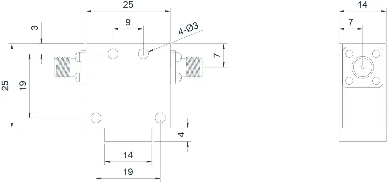
Here are commonly used products of Coaxial Isolators. This product covers the S~C band range with a relative bandwidth of up to 10%. Dimensions, ports, and frequency bands can be customized based on your requirements.
| Model | Frequency(GHz) | BW Max | Insertion loss(dB) Max | Isolation(dB)Min | VSWR Max | Connector | operating temperature(℃) | PK/CW/RP(Watt) | Direction |
|---|---|---|---|---|---|---|---|---|---|
| HCITA30T50G⬇ | 3.0~5.0 | 10% | 0.4 | 20 | 1.2 | SMA | -55~+85℃ | 200/40/15 | Clockwise |
| HCITB30T50G⬇ | 3.0~5.0 | 10% | 0.4 | 20 | 1.2 | SMA | -55~+85℃ | 200/40/15 | Counter Clockwise |
4.0~8.0GHz Typical Coaxial Isolator
Product Overview
Here are commonly used products of Coaxial Isolators. This product covers the C- band range with a
relative bandwidth of up to 10%. Dimensions, ports, and frequency bands can be customized based on your
requirements.
Model
Frequency(GHz)
BW Max
Insertion loss(dB) Max
Isolation(dB)Min
VSWR Max
Connector
operating temperature(℃)
PK/CW/RP(Watt)
Direction
HCITA40T80G⬇
4.0~8.0
10%
0.4
20
1.2
SMA
-55~+85℃
400/40/15
Clockwise
HCITB40T80G⬇
4.0~8.0
10%
0.4
20
1.2
SMA
-55~+85℃
400/40/15
Counter Clockwise
8.0~19.0GHz Typical Coaxial Isolator
Product Overview
Here are commonly used products of Coaxial Isolators. This product covers the X Ku K- band range with a
relative bandwidth of up to 10%. Dimensions, ports, and frequency bands can be customized based on your
requirements.
Model
Frequency(GHz)
BW Max
Insertion loss(dB) Max
Isolation(dB)Min
VSWR Max
Connector
operating temperature(℃)
PK/CW/RP(Watt)
Direction
HCITA80T190G⬇
8.0~19.0
10%
0.4
20
1.25
SMA
-55~+85℃
200/40/15
Clockwise
HCITB80T190G⬇
8.0~19.0
10%
0.4
20
1.25
SMA
-55~+85℃
200/40/15
Counter Clockwise
20.0~25.0GHz Typical Coaxial Isolator
Product Overview
Here are commonly used products of Coaxial Isolators. This product covers the K- band range with a
relative bandwidth of up to 22.22%. Dimensions, ports, and frequency bands can be customized based on
your requirements.
Model
Frequency(GHz)
BW Max
Insertion loss(dB) Max
Isolation(dB)Min
VSWR Max
Connector
operating temperature(℃)
PK/CW/RP(Watt)
Direction
HCITA200T250G⬇
20.0~25.0
FULL
1.1
23
1.25
SMA
-55~+85℃
-/10/-
Clockwise
HCITB200T250G⬇
20.0~25.0
FULL
1.1
23
1.25
SMA
-55~+85℃
-/10/-
Counter Clockwise
18.0~40.0GHz Typical Coaxial Isolator
Product Overview
Here are commonly used products of Coaxial Isolators. This product covers the Ku K- band range with a
relative bandwidth of up to 10%. Dimensions, ports, and frequency bands can be customized based on your
requirements.
Model
Frequency(GHz)
BW Max
Insertion loss(dB) Max
Isolation(dB)Min
VSWR Max
Connector
operating temperature(℃)
PK/CW/RP(Watt)
Direction
HCITA180T400G⬇
18.0~40.0
10%
0.6
18
1.35
2.92
-55~+85℃
20/5/1
Clockwise
HCITB180T400G⬇
18.0~40.0
10%
0.6
18
1.35
2.92
-55~+85℃
20/5/1
Counter Clockwise
About HzBeat
HzBeat is a leading RF component manufacturer specializing in RF circulators and isolators, as a global supplier of RF circulators and isolators (20MHz–200GHz), we providing microstrip, drop-in, coaxial, and waveguide solutions for communication systems, radar, satellite, and medical imaging.
For detailed technical documentation, sample requests, or customization needs, please do not hesitate to contact us. — we respond within 24 hours to ensure you get precise solutions for your design.
Customization & Selection Guide
- Operating Band:Ensure it covers all frequencies required by your system.
- Power Handling Capacity:Select based on your system's transmit power (average and peak), allowing a certain margin.
- Performance Requirements:Define specific requirements for Insertion Loss, Isolation, and VSWR/Return Loss.
- Environmental Conditions:Consider operating temperature range, vibration, humidity, etc.
- Cost & Delivery:Balance cost and project timeline while meeting performance requirements.
Why Choose Our Product
- Profound Technical Expertise:We have over 18 years of R&D experience in ferrite materials and microwave magnetics.
- Fully Automated Production Lines:Ensure consistent excellence and reliability in every unit.
- Professional Application Support:Our engineering team provides timely technical selection, customization, and failure analysis services.
- Competitive Pricing & Lead Times:Economies of scale from mass production enable us to respond quickly to your orders.
Related Products
Questions? Feel Free to Reach Out Via Message.
Tell us frequency band, target IL/Isolation/VSWR, power level and timeline — we’ll match the best topology and deliver S-parameters.We will contact you within 24 hours.
Product Overview
Here are commonly used products of Coaxial Isolators. This product covers the C- band range with a relative bandwidth of up to 10%. Dimensions, ports, and frequency bands can be customized based on your requirements.
| Model | Frequency(GHz) | BW Max | Insertion loss(dB) Max | Isolation(dB)Min | VSWR Max | Connector | operating temperature(℃) | PK/CW/RP(Watt) | Direction |
|---|---|---|---|---|---|---|---|---|---|
| HCITA40T80G⬇ | 4.0~8.0 | 10% | 0.4 | 20 | 1.2 | SMA | -55~+85℃ | 400/40/15 | Clockwise |
| HCITB40T80G⬇ | 4.0~8.0 | 10% | 0.4 | 20 | 1.2 | SMA | -55~+85℃ | 400/40/15 | Counter Clockwise |
8.0~19.0GHz Typical Coaxial Isolator
Product Overview
Here are commonly used products of Coaxial Isolators. This product covers the X Ku K- band range with a
relative bandwidth of up to 10%. Dimensions, ports, and frequency bands can be customized based on your
requirements.
Model
Frequency(GHz)
BW Max
Insertion loss(dB) Max
Isolation(dB)Min
VSWR Max
Connector
operating temperature(℃)
PK/CW/RP(Watt)
Direction
HCITA80T190G⬇
8.0~19.0
10%
0.4
20
1.25
SMA
-55~+85℃
200/40/15
Clockwise
HCITB80T190G⬇
8.0~19.0
10%
0.4
20
1.25
SMA
-55~+85℃
200/40/15
Counter Clockwise
20.0~25.0GHz Typical Coaxial Isolator
Product Overview
Here are commonly used products of Coaxial Isolators. This product covers the K- band range with a
relative bandwidth of up to 22.22%. Dimensions, ports, and frequency bands can be customized based on
your requirements.
Model
Frequency(GHz)
BW Max
Insertion loss(dB) Max
Isolation(dB)Min
VSWR Max
Connector
operating temperature(℃)
PK/CW/RP(Watt)
Direction
HCITA200T250G⬇
20.0~25.0
FULL
1.1
23
1.25
SMA
-55~+85℃
-/10/-
Clockwise
HCITB200T250G⬇
20.0~25.0
FULL
1.1
23
1.25
SMA
-55~+85℃
-/10/-
Counter Clockwise
18.0~40.0GHz Typical Coaxial Isolator
Product Overview
Here are commonly used products of Coaxial Isolators. This product covers the Ku K- band range with a
relative bandwidth of up to 10%. Dimensions, ports, and frequency bands can be customized based on your
requirements.
Model
Frequency(GHz)
BW Max
Insertion loss(dB) Max
Isolation(dB)Min
VSWR Max
Connector
operating temperature(℃)
PK/CW/RP(Watt)
Direction
HCITA180T400G⬇
18.0~40.0
10%
0.6
18
1.35
2.92
-55~+85℃
20/5/1
Clockwise
HCITB180T400G⬇
18.0~40.0
10%
0.6
18
1.35
2.92
-55~+85℃
20/5/1
Counter Clockwise
About HzBeat
HzBeat is a leading RF component manufacturer specializing in RF circulators and isolators, as a global supplier of RF circulators and isolators (20MHz–200GHz), we providing microstrip, drop-in, coaxial, and waveguide solutions for communication systems, radar, satellite, and medical imaging.
For detailed technical documentation, sample requests, or customization needs, please do not hesitate to contact us. — we respond within 24 hours to ensure you get precise solutions for your design.
Customization & Selection Guide
- Operating Band:Ensure it covers all frequencies required by your system.
- Power Handling Capacity:Select based on your system's transmit power (average and peak), allowing a certain margin.
- Performance Requirements:Define specific requirements for Insertion Loss, Isolation, and VSWR/Return Loss.
- Environmental Conditions:Consider operating temperature range, vibration, humidity, etc.
- Cost & Delivery:Balance cost and project timeline while meeting performance requirements.
Why Choose Our Product
- Profound Technical Expertise:We have over 18 years of R&D experience in ferrite materials and microwave magnetics.
- Fully Automated Production Lines:Ensure consistent excellence and reliability in every unit.
- Professional Application Support:Our engineering team provides timely technical selection, customization, and failure analysis services.
- Competitive Pricing & Lead Times:Economies of scale from mass production enable us to respond quickly to your orders.
Related Products
Questions? Feel Free to Reach Out Via Message.
Tell us frequency band, target IL/Isolation/VSWR, power level and timeline — we’ll match the best topology and deliver S-parameters.We will contact you within 24 hours.
Product Overview
Here are commonly used products of Coaxial Isolators. This product covers the X Ku K- band range with a relative bandwidth of up to 10%. Dimensions, ports, and frequency bands can be customized based on your requirements.
| Model | Frequency(GHz) | BW Max | Insertion loss(dB) Max | Isolation(dB)Min | VSWR Max | Connector | operating temperature(℃) | PK/CW/RP(Watt) | Direction |
|---|---|---|---|---|---|---|---|---|---|
| HCITA80T190G⬇ | 8.0~19.0 | 10% | 0.4 | 20 | 1.25 | SMA | -55~+85℃ | 200/40/15 | Clockwise |
| HCITB80T190G⬇ | 8.0~19.0 | 10% | 0.4 | 20 | 1.25 | SMA | -55~+85℃ | 200/40/15 | Counter Clockwise |
20.0~25.0GHz Typical Coaxial Isolator
Product Overview
Here are commonly used products of Coaxial Isolators. This product covers the K- band range with a
relative bandwidth of up to 22.22%. Dimensions, ports, and frequency bands can be customized based on
your requirements.
Model
Frequency(GHz)
BW Max
Insertion loss(dB) Max
Isolation(dB)Min
VSWR Max
Connector
operating temperature(℃)
PK/CW/RP(Watt)
Direction
HCITA200T250G⬇
20.0~25.0
FULL
1.1
23
1.25
SMA
-55~+85℃
-/10/-
Clockwise
HCITB200T250G⬇
20.0~25.0
FULL
1.1
23
1.25
SMA
-55~+85℃
-/10/-
Counter Clockwise
18.0~40.0GHz Typical Coaxial Isolator
Product Overview
Here are commonly used products of Coaxial Isolators. This product covers the Ku K- band range with a
relative bandwidth of up to 10%. Dimensions, ports, and frequency bands can be customized based on your
requirements.
Model
Frequency(GHz)
BW Max
Insertion loss(dB) Max
Isolation(dB)Min
VSWR Max
Connector
operating temperature(℃)
PK/CW/RP(Watt)
Direction
HCITA180T400G⬇
18.0~40.0
10%
0.6
18
1.35
2.92
-55~+85℃
20/5/1
Clockwise
HCITB180T400G⬇
18.0~40.0
10%
0.6
18
1.35
2.92
-55~+85℃
20/5/1
Counter Clockwise
About HzBeat
HzBeat is a leading RF component manufacturer specializing in RF circulators and isolators, as a global supplier of RF circulators and isolators (20MHz–200GHz), we providing microstrip, drop-in, coaxial, and waveguide solutions for communication systems, radar, satellite, and medical imaging.
For detailed technical documentation, sample requests, or customization needs, please do not hesitate to contact us. — we respond within 24 hours to ensure you get precise solutions for your design.
Customization & Selection Guide
- Operating Band:Ensure it covers all frequencies required by your system.
- Power Handling Capacity:Select based on your system's transmit power (average and peak), allowing a certain margin.
- Performance Requirements:Define specific requirements for Insertion Loss, Isolation, and VSWR/Return Loss.
- Environmental Conditions:Consider operating temperature range, vibration, humidity, etc.
- Cost & Delivery:Balance cost and project timeline while meeting performance requirements.
Why Choose Our Product
- Profound Technical Expertise:We have over 18 years of R&D experience in ferrite materials and microwave magnetics.
- Fully Automated Production Lines:Ensure consistent excellence and reliability in every unit.
- Professional Application Support:Our engineering team provides timely technical selection, customization, and failure analysis services.
- Competitive Pricing & Lead Times:Economies of scale from mass production enable us to respond quickly to your orders.
Related Products
Questions? Feel Free to Reach Out Via Message.
Tell us frequency band, target IL/Isolation/VSWR, power level and timeline — we’ll match the best topology and deliver S-parameters.We will contact you within 24 hours.
Product Overview
Here are commonly used products of Coaxial Isolators. This product covers the K- band range with a relative bandwidth of up to 22.22%. Dimensions, ports, and frequency bands can be customized based on your requirements.
| Model | Frequency(GHz) | BW Max | Insertion loss(dB) Max | Isolation(dB)Min | VSWR Max | Connector | operating temperature(℃) | PK/CW/RP(Watt) | Direction |
|---|---|---|---|---|---|---|---|---|---|
| HCITA200T250G⬇ | 20.0~25.0 | FULL | 1.1 | 23 | 1.25 | SMA | -55~+85℃ | -/10/- | Clockwise |
| HCITB200T250G⬇ | 20.0~25.0 | FULL | 1.1 | 23 | 1.25 | SMA | -55~+85℃ | -/10/- | Counter Clockwise |
18.0~40.0GHz Typical Coaxial Isolator
Product Overview
Here are commonly used products of Coaxial Isolators. This product covers the Ku K- band range with a
relative bandwidth of up to 10%. Dimensions, ports, and frequency bands can be customized based on your
requirements.
Model
Frequency(GHz)
BW Max
Insertion loss(dB) Max
Isolation(dB)Min
VSWR Max
Connector
operating temperature(℃)
PK/CW/RP(Watt)
Direction
HCITA180T400G⬇
18.0~40.0
10%
0.6
18
1.35
2.92
-55~+85℃
20/5/1
Clockwise
HCITB180T400G⬇
18.0~40.0
10%
0.6
18
1.35
2.92
-55~+85℃
20/5/1
Counter Clockwise
About HzBeat
HzBeat is a leading RF component manufacturer specializing in RF circulators and isolators, as a global supplier of RF circulators and isolators (20MHz–200GHz), we providing microstrip, drop-in, coaxial, and waveguide solutions for communication systems, radar, satellite, and medical imaging.
For detailed technical documentation, sample requests, or customization needs, please do not hesitate to contact us. — we respond within 24 hours to ensure you get precise solutions for your design.
Customization & Selection Guide
- Operating Band:Ensure it covers all frequencies required by your system.
- Power Handling Capacity:Select based on your system's transmit power (average and peak), allowing a certain margin.
- Performance Requirements:Define specific requirements for Insertion Loss, Isolation, and VSWR/Return Loss.
- Environmental Conditions:Consider operating temperature range, vibration, humidity, etc.
- Cost & Delivery:Balance cost and project timeline while meeting performance requirements.
Why Choose Our Product
- Profound Technical Expertise:We have over 18 years of R&D experience in ferrite materials and microwave magnetics.
- Fully Automated Production Lines:Ensure consistent excellence and reliability in every unit.
- Professional Application Support:Our engineering team provides timely technical selection, customization, and failure analysis services.
- Competitive Pricing & Lead Times:Economies of scale from mass production enable us to respond quickly to your orders.
Related Products
Questions? Feel Free to Reach Out Via Message.
Tell us frequency band, target IL/Isolation/VSWR, power level and timeline — we’ll match the best topology and deliver S-parameters.We will contact you within 24 hours.
Product Overview
Here are commonly used products of Coaxial Isolators. This product covers the Ku K- band range with a relative bandwidth of up to 10%. Dimensions, ports, and frequency bands can be customized based on your requirements.
| Model | Frequency(GHz) | BW Max | Insertion loss(dB) Max | Isolation(dB)Min | VSWR Max | Connector | operating temperature(℃) | PK/CW/RP(Watt) | Direction |
|---|---|---|---|---|---|---|---|---|---|
| HCITA180T400G⬇ | 18.0~40.0 | 10% | 0.6 | 18 | 1.35 | 2.92 | -55~+85℃ | 20/5/1 | Clockwise |
| HCITB180T400G⬇ | 18.0~40.0 | 10% | 0.6 | 18 | 1.35 | 2.92 | -55~+85℃ | 20/5/1 | Counter Clockwise |
About HzBeat
HzBeat is a leading RF component manufacturer specializing in RF circulators and isolators, as a global supplier of RF circulators and isolators (20MHz–200GHz), we providing microstrip, drop-in, coaxial, and waveguide solutions for communication systems, radar, satellite, and medical imaging.
For detailed technical documentation, sample requests, or customization needs, please do not hesitate to contact us. — we respond within 24 hours to ensure you get precise solutions for your design.
Customization & Selection Guide
- Operating Band:Ensure it covers all frequencies required by your system.
- Power Handling Capacity:Select based on your system's transmit power (average and peak), allowing a certain margin.
- Performance Requirements:Define specific requirements for Insertion Loss, Isolation, and VSWR/Return Loss.
- Environmental Conditions:Consider operating temperature range, vibration, humidity, etc.
- Cost & Delivery:Balance cost and project timeline while meeting performance requirements.
Why Choose Our Product
- Profound Technical Expertise:We have over 18 years of R&D experience in ferrite materials and microwave magnetics.
- Fully Automated Production Lines:Ensure consistent excellence and reliability in every unit.
- Professional Application Support:Our engineering team provides timely technical selection, customization, and failure analysis services.
- Competitive Pricing & Lead Times:Economies of scale from mass production enable us to respond quickly to your orders.