Home/ Dual-Junction Microstrip Circulator/ Typical Dual-Junction Microstrip Circulator
Typical Dual-Junction Microstrip Circulator
- The following products are broadband Microstrip Isolators designed with a compact form factor, covering the frequency range from the S-band to the K-band, with a maximum relative bandwidth of up to 100%.
Electrical Performance Table and Product Appearance
5.0~6.0GHz Typical Dual-Junction Microstrip Circulator
Product Overview
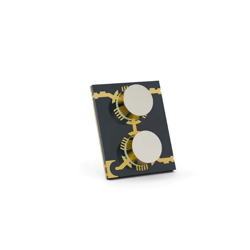
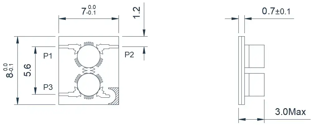
This is a C-band Microstrip Dual-Junction Circulator. As shown in the diagram, the circuit is arranged
diagonally to narrow the signal transmission channel width. However, it results in longer signal
transmission distances and some sacrifices in terms of loss. This kind of solution can be customized
based on your requirements to achieve a narrower signal transmission channel width.
Model
Frequency(GHz)
BW Max
Insertion loss(dB) Max
Isolation(dB)Min
VSWR Max
operating temperature(℃ )
PK/CW/RP(Watt)
Direction
HMDHA50T60G⬇
5.0~6.0
FULL
0.5(P1-P2)
0.9(P2-P3)
18.0(P2-P1)
30.0(P3-P2)
1.35
-55~+85
30/15/5
Clockwise
HMDHB50T60G⬇
5.0~6.0
FULL
0.5(P1-P2)
0.9(P2-P3)
18.0(P2-P1)
30.0(P3-P2)
1.35
-55~+85
30/15/5
Clockwise
5.0~6.0GHz Typical Dual-Junction Microstrip Circulator
Product Overview
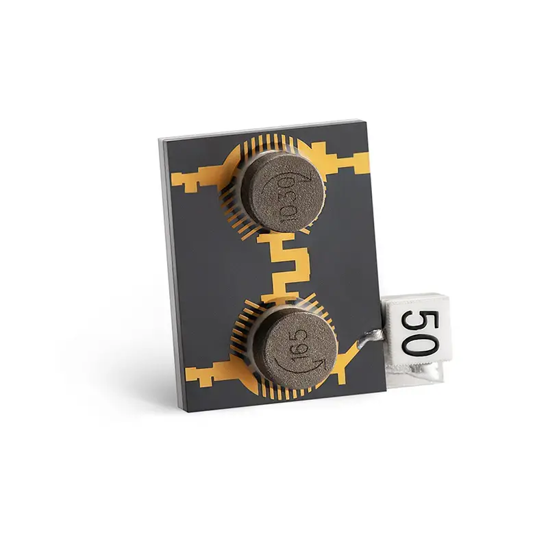
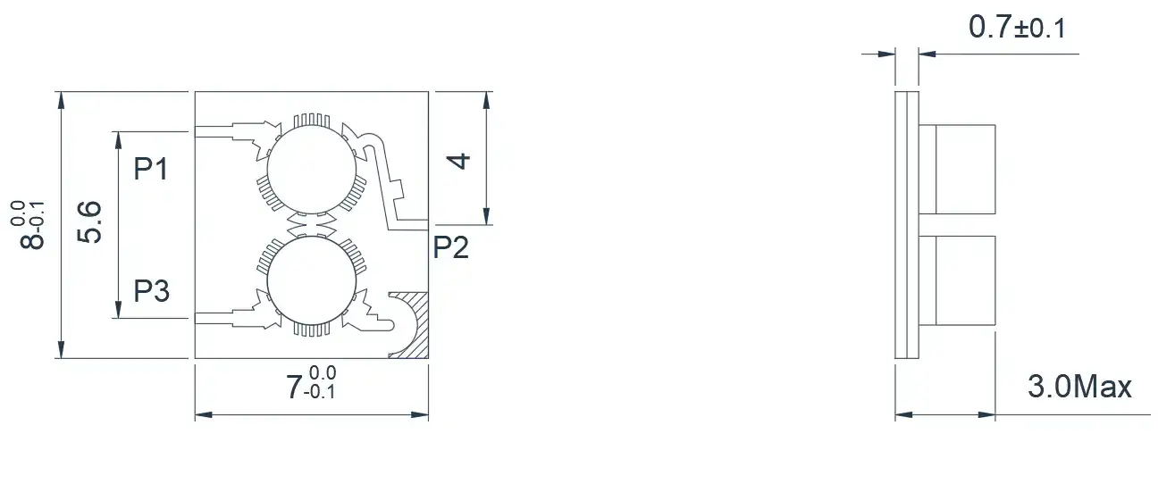
This is a C-band Microstrip Dual-Junction Circulator. As shown in the diagram, the load port has been
transformed into an external load, significantly increasing the reflected power tolerance and providing
better protection for the transmitting end. It can be customized based on frequency bands, power, and
size requirements.
Model
Frequency(GHz)
BW Max
Insertion loss(dB) Max
Isolation(dB)Min
VSWR Max
operating temperature(℃ )
PK/CW/RP(Watt)
Direction
HMDHA50T60G-R⬇
5.0~6.0
FULL
0.5(P1-P2)
0.9(P2-P3)
20.0(P2-P1)
30.0(P3-P2)
1.25
-55~+85
30/15/5
Clockwise
HMDHB50T60G-R⬇
5.0~6.0
FULL
0.5(P1-P2)
0.9(P2-P3)
20.0(P2-P1)
30.0(P3-P2)
1.35
-55~+85
30/15/5
Counter Clockwise
8.0~12.0GHz Typical Dual-Junction Microstrip Circulator
Product Overview
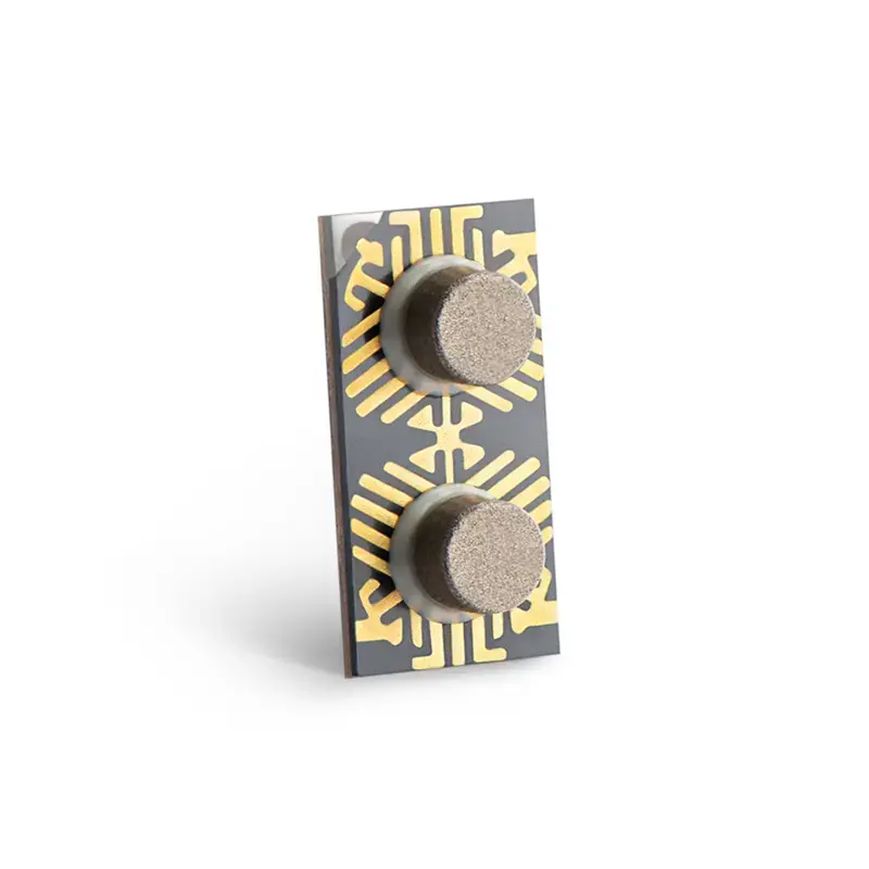
This is a standard X-band Microstrip Dual-Junction Circulator. It can be customized based on frequency
bands, power, and size requirements.
Model
Frequency(GHz)
BW Max
Insertion loss(dB) Max
Isolation(dB)Min
VSWR Max
operating temperature(℃ )
PK/CW/RP(Watt)
Direction
HMDHA80T120G⬇
8.0~12.0
FULL
0.6(P1-P2)
1.2(P2-P3)
16.0(P2-P1)
28.0(P3-P2)
1.35
-55~+85
20/10/3
Clockwise
HMDHB80T120G⬇
8.0~12.0
FULL
0.6(P1-P2)
1.2(P2-P3)
16.0(P2-P1)
28.0(P3-P2)
1.35
-55~+85
20/10/3
Counter Clockwise
HMDHA85T105G⬇
8.5~10.5
FULL
0.4(P1-P2)
0.8(P2-P3)
20.0(P2-P1)
30.0(P3-P2)
1.25
-55~+85
20/10/3
Clockwise
HMDHB85T105G⬇
8.5~10.5
FULL
0.4(P1-P2)
0.8(P2-P3)
20.0(P2-P1)
30.0(P3-P2)
1.25
-55~+85
20/10/3
Counter Clockwise
8.0~12.0GHz Typical Dual-Junction Microstrip Circulator
Product Overview
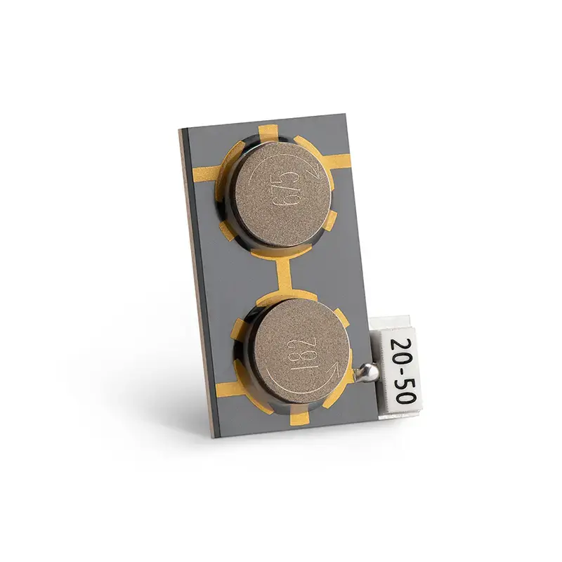
This is an X-band Microstrip Dual-Junction Circulator. As shown in the diagram, the antenna port has
been moved to the center position, making it more convenient for customer engineers to design their
circuits according to the usage scenario. It can be customized based on frequency bands, power, and size
requirements.
Model
Frequency(GHz)
BW Max
Insertion loss(dB) Max
Isolation(dB)Min
VSWR Max
operating temperature(℃ )
PK/CW/RP(Watt)
Direction
HMDYA80T120G⬇
8.0~12.0
FULL
0.65(P1-P2)
1.3(P2-P3)
16.0(P2-P1)
28.0(P3-P2)
1.35
-55~+85
20/10/3
Clockwise
HMDYB80T120G⬇
8.0~12.0
FULL
0.65(P1-P2)
1.3(P2-P3)
16.0(P2-P1)
28.0(P3-P2)
1.35
-55~+85
20/10/3
Counter Clockwise
HMDYA85T105G⬇
8.5~10.5
FULL
0.5(P1-P2)
0.9(P2-P3)
20.0(P2-P1)
30.0(P3-P2)
1.25
-55~+85
20/10/3
Clockwise
HMDYB85T105G⬇
8.5~10.5
FULL
0.5(P1-P2)
0.9(P2-P3)
20.0(P2-P1)
30.0(P3-P2)
1.25
-55~+85
20/10/3
Counter Clockwise
14.0~18.0GHz Typical Dual-Junction Microstrip Circulator
Product Overview
This is a standard Ku-band Microstrip Dual-Junction Circulator. It can be customized based on frequency
bands, power, and size requirements.
Model
Frequency(GHz)
BW Max
Insertion loss(dB) Max
Isolation(dB)Min
VSWR Max
operating temperature(℃ )
PK/CW/RP(Watt)
Direction
HMDHA140T180G⬇
14.0~18.0
FULL
0.5(P1-P2)
0.9(P2-P3)
17.0(P2-P1)
28.0(P3-P2)
1.3
-55~+85
20/10/3
Clockwise
HMDHB140T180G⬇
14.0~18.0
FULL
0.5(P1-P2)
0.9(P2-P3)
17.0(P2-P1)
28.0(P3-P2)
1.3
-55~+85
20/10/3
Counter Clockwise
14.0~18.0GHz Typical Dual-Junction Microstrip Circulator
Product Overview
This is an Ku-band Microstrip Dual-Junction Circulator. As shown in the diagram, the antenna port has
been moved to the center position, making it more convenient for customer engineers to design their
circuits according to the usage scenario. It can be customized based on frequency bands, power, and size
requirements.
Model
Frequency(GHz)
BW Max
Insertion loss(dB) Max
Isolation(dB)Min
VSWR Max
operating temperature(℃ )
PK/CW/RP(Watt)
Direction
HMDYA140T180G⬇
14.0~18.0
FULL
0.6(P1-P2)
1.1(P2-P3)
16.0(P2-P1)
28.0(P3-P2)
1.35
-55~+85
20/10/3
Clockwise
HMDYB140T180G⬇
14.0~18.0
FULL
0.6(P1-P2)
1.1(P2-P3)
16.0(P2-P1)
28.0(P3-P2)
1.35
-55~+85
20/10/3
Counter Clockwise
About HzBeat
HzBeat is a leading RF component manufacturer specializing in RF circulators and isolators, as a global supplier of RF circulators and isolators (20MHz–200GHz), we providing microstrip, drop-in, coaxial, and waveguide solutions for communication systems, radar, satellite, and medical imaging.
For detailed technical documentation, sample requests, or customization needs, please do not hesitate to contact us. — we respond within 24 hours to ensure you get precise solutions for your design.
Customization & Selection Guide
- Operating Band:Ensure it covers all frequencies required by your system.
- Power Handling Capacity:Select based on your system's transmit power (average and peak), allowing a certain margin.
- Performance Requirements:Define specific requirements for Insertion Loss, Isolation, and VSWR/Return Loss.
- Environmental Conditions:Consider operating temperature range, vibration, humidity, etc.
- Cost & Delivery:Balance cost and project timeline while meeting performance requirements.
Why Choose Our Product
- Profound Technical Expertise:We have over 18 years of R&D experience in ferrite materials and microwave magnetics.
- Fully Automated Production Lines:Ensure consistent excellence and reliability in every unit.
- Professional Application Support:Our engineering team provides timely technical selection, customization, and failure analysis services.
- Competitive Pricing & Lead Times:Economies of scale from mass production enable us to respond quickly to your orders.
Related Products
Questions? Feel Free to Reach Out Via Message.
Tell us frequency band, target IL/Isolation/VSWR, power level and timeline — we’ll match the best topology and deliver S-parameters.We will contact you within 24 hours.
Product Overview
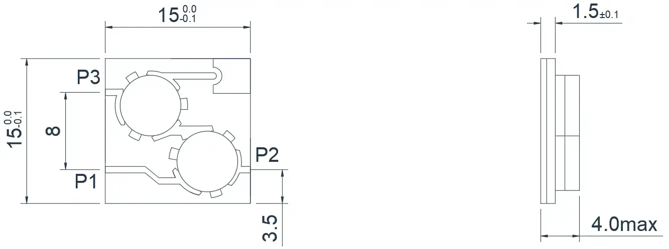
This is a C-band Microstrip Dual-Junction Circulator. As shown in the diagram, the circuit is arranged diagonally to narrow the signal transmission channel width. However, it results in longer signal transmission distances and some sacrifices in terms of loss. This kind of solution can be customized based on your requirements to achieve a narrower signal transmission channel width.
| Model | Frequency(GHz) | BW Max | Insertion loss(dB) Max | Isolation(dB)Min | VSWR Max | operating temperature(℃ ) | PK/CW/RP(Watt) | Direction |
|---|---|---|---|---|---|---|---|---|
| HMDHA50T60G⬇ |
5.0~6.0 |
FULL |
0.5(P1-P2) 0.9(P2-P3) |
18.0(P2-P1) 30.0(P3-P2) |
1.35 | -55~+85 | 30/15/5 | Clockwise |
| HMDHB50T60G⬇ |
5.0~6.0 |
FULL |
0.5(P1-P2) 0.9(P2-P3) |
18.0(P2-P1) 30.0(P3-P2) |
1.35 | -55~+85 | 30/15/5 | Clockwise |
5.0~6.0GHz Typical Dual-Junction Microstrip Circulator
Product Overview
This is a C-band Microstrip Dual-Junction Circulator. As shown in the diagram, the load port has been
transformed into an external load, significantly increasing the reflected power tolerance and providing
better protection for the transmitting end. It can be customized based on frequency bands, power, and
size requirements.
Model
Frequency(GHz)
BW Max
Insertion loss(dB) Max
Isolation(dB)Min
VSWR Max
operating temperature(℃ )
PK/CW/RP(Watt)
Direction
HMDHA50T60G-R⬇
5.0~6.0
FULL
0.5(P1-P2)
0.9(P2-P3)
20.0(P2-P1)
30.0(P3-P2)
1.25
-55~+85
30/15/5
Clockwise
HMDHB50T60G-R⬇
5.0~6.0
FULL
0.5(P1-P2)
0.9(P2-P3)
20.0(P2-P1)
30.0(P3-P2)
1.35
-55~+85
30/15/5
Counter Clockwise
8.0~12.0GHz Typical Dual-Junction Microstrip Circulator
Product Overview
This is a standard X-band Microstrip Dual-Junction Circulator. It can be customized based on frequency
bands, power, and size requirements.
Model
Frequency(GHz)
BW Max
Insertion loss(dB) Max
Isolation(dB)Min
VSWR Max
operating temperature(℃ )
PK/CW/RP(Watt)
Direction
HMDHA80T120G⬇
8.0~12.0
FULL
0.6(P1-P2)
1.2(P2-P3)
16.0(P2-P1)
28.0(P3-P2)
1.35
-55~+85
20/10/3
Clockwise
HMDHB80T120G⬇
8.0~12.0
FULL
0.6(P1-P2)
1.2(P2-P3)
16.0(P2-P1)
28.0(P3-P2)
1.35
-55~+85
20/10/3
Counter Clockwise
HMDHA85T105G⬇
8.5~10.5
FULL
0.4(P1-P2)
0.8(P2-P3)
20.0(P2-P1)
30.0(P3-P2)
1.25
-55~+85
20/10/3
Clockwise
HMDHB85T105G⬇
8.5~10.5
FULL
0.4(P1-P2)
0.8(P2-P3)
20.0(P2-P1)
30.0(P3-P2)
1.25
-55~+85
20/10/3
Counter Clockwise
8.0~12.0GHz Typical Dual-Junction Microstrip Circulator
Product Overview
This is an X-band Microstrip Dual-Junction Circulator. As shown in the diagram, the antenna port has
been moved to the center position, making it more convenient for customer engineers to design their
circuits according to the usage scenario. It can be customized based on frequency bands, power, and size
requirements.
Model
Frequency(GHz)
BW Max
Insertion loss(dB) Max
Isolation(dB)Min
VSWR Max
operating temperature(℃ )
PK/CW/RP(Watt)
Direction
HMDYA80T120G⬇
8.0~12.0
FULL
0.65(P1-P2)
1.3(P2-P3)
16.0(P2-P1)
28.0(P3-P2)
1.35
-55~+85
20/10/3
Clockwise
HMDYB80T120G⬇
8.0~12.0
FULL
0.65(P1-P2)
1.3(P2-P3)
16.0(P2-P1)
28.0(P3-P2)
1.35
-55~+85
20/10/3
Counter Clockwise
HMDYA85T105G⬇
8.5~10.5
FULL
0.5(P1-P2)
0.9(P2-P3)
20.0(P2-P1)
30.0(P3-P2)
1.25
-55~+85
20/10/3
Clockwise
HMDYB85T105G⬇
8.5~10.5
FULL
0.5(P1-P2)
0.9(P2-P3)
20.0(P2-P1)
30.0(P3-P2)
1.25
-55~+85
20/10/3
Counter Clockwise
14.0~18.0GHz Typical Dual-Junction Microstrip Circulator
Product Overview
This is a standard Ku-band Microstrip Dual-Junction Circulator. It can be customized based on frequency
bands, power, and size requirements.
Model
Frequency(GHz)
BW Max
Insertion loss(dB) Max
Isolation(dB)Min
VSWR Max
operating temperature(℃ )
PK/CW/RP(Watt)
Direction
HMDHA140T180G⬇
14.0~18.0
FULL
0.5(P1-P2)
0.9(P2-P3)
17.0(P2-P1)
28.0(P3-P2)
1.3
-55~+85
20/10/3
Clockwise
HMDHB140T180G⬇
14.0~18.0
FULL
0.5(P1-P2)
0.9(P2-P3)
17.0(P2-P1)
28.0(P3-P2)
1.3
-55~+85
20/10/3
Counter Clockwise
14.0~18.0GHz Typical Dual-Junction Microstrip Circulator
Product Overview
This is an Ku-band Microstrip Dual-Junction Circulator. As shown in the diagram, the antenna port has
been moved to the center position, making it more convenient for customer engineers to design their
circuits according to the usage scenario. It can be customized based on frequency bands, power, and size
requirements.
Model
Frequency(GHz)
BW Max
Insertion loss(dB) Max
Isolation(dB)Min
VSWR Max
operating temperature(℃ )
PK/CW/RP(Watt)
Direction
HMDYA140T180G⬇
14.0~18.0
FULL
0.6(P1-P2)
1.1(P2-P3)
16.0(P2-P1)
28.0(P3-P2)
1.35
-55~+85
20/10/3
Clockwise
HMDYB140T180G⬇
14.0~18.0
FULL
0.6(P1-P2)
1.1(P2-P3)
16.0(P2-P1)
28.0(P3-P2)
1.35
-55~+85
20/10/3
Counter Clockwise
About HzBeat
HzBeat is a leading RF component manufacturer specializing in RF circulators and isolators, as a global supplier of RF circulators and isolators (20MHz–200GHz), we providing microstrip, drop-in, coaxial, and waveguide solutions for communication systems, radar, satellite, and medical imaging.
For detailed technical documentation, sample requests, or customization needs, please do not hesitate to contact us. — we respond within 24 hours to ensure you get precise solutions for your design.
Customization & Selection Guide
- Operating Band:Ensure it covers all frequencies required by your system.
- Power Handling Capacity:Select based on your system's transmit power (average and peak), allowing a certain margin.
- Performance Requirements:Define specific requirements for Insertion Loss, Isolation, and VSWR/Return Loss.
- Environmental Conditions:Consider operating temperature range, vibration, humidity, etc.
- Cost & Delivery:Balance cost and project timeline while meeting performance requirements.
Why Choose Our Product
- Profound Technical Expertise:We have over 18 years of R&D experience in ferrite materials and microwave magnetics.
- Fully Automated Production Lines:Ensure consistent excellence and reliability in every unit.
- Professional Application Support:Our engineering team provides timely technical selection, customization, and failure analysis services.
- Competitive Pricing & Lead Times:Economies of scale from mass production enable us to respond quickly to your orders.
Related Products
Questions? Feel Free to Reach Out Via Message.
Tell us frequency band, target IL/Isolation/VSWR, power level and timeline — we’ll match the best topology and deliver S-parameters.We will contact you within 24 hours.
Product Overview
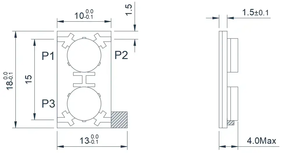
This is a C-band Microstrip Dual-Junction Circulator. As shown in the diagram, the load port has been transformed into an external load, significantly increasing the reflected power tolerance and providing better protection for the transmitting end. It can be customized based on frequency bands, power, and size requirements.
| Model | Frequency(GHz) | BW Max | Insertion loss(dB) Max | Isolation(dB)Min | VSWR Max | operating temperature(℃ ) | PK/CW/RP(Watt) | Direction |
|---|---|---|---|---|---|---|---|---|
| HMDHA50T60G-R⬇ |
5.0~6.0 |
FULL |
0.5(P1-P2) 0.9(P2-P3) |
20.0(P2-P1) 30.0(P3-P2) |
1.25 | -55~+85 | 30/15/5 | Clockwise |
| HMDHB50T60G-R⬇ |
5.0~6.0 |
FULL |
0.5(P1-P2) 0.9(P2-P3) |
20.0(P2-P1) 30.0(P3-P2) |
1.35 | -55~+85 | 30/15/5 | Counter Clockwise |
8.0~12.0GHz Typical Dual-Junction Microstrip Circulator
Product Overview
This is a standard X-band Microstrip Dual-Junction Circulator. It can be customized based on frequency
bands, power, and size requirements.
Model
Frequency(GHz)
BW Max
Insertion loss(dB) Max
Isolation(dB)Min
VSWR Max
operating temperature(℃ )
PK/CW/RP(Watt)
Direction
HMDHA80T120G⬇
8.0~12.0
FULL
0.6(P1-P2)
1.2(P2-P3)
16.0(P2-P1)
28.0(P3-P2)
1.35
-55~+85
20/10/3
Clockwise
HMDHB80T120G⬇
8.0~12.0
FULL
0.6(P1-P2)
1.2(P2-P3)
16.0(P2-P1)
28.0(P3-P2)
1.35
-55~+85
20/10/3
Counter Clockwise
HMDHA85T105G⬇
8.5~10.5
FULL
0.4(P1-P2)
0.8(P2-P3)
20.0(P2-P1)
30.0(P3-P2)
1.25
-55~+85
20/10/3
Clockwise
HMDHB85T105G⬇
8.5~10.5
FULL
0.4(P1-P2)
0.8(P2-P3)
20.0(P2-P1)
30.0(P3-P2)
1.25
-55~+85
20/10/3
Counter Clockwise
8.0~12.0GHz Typical Dual-Junction Microstrip Circulator
Product Overview
This is an X-band Microstrip Dual-Junction Circulator. As shown in the diagram, the antenna port has
been moved to the center position, making it more convenient for customer engineers to design their
circuits according to the usage scenario. It can be customized based on frequency bands, power, and size
requirements.
Model
Frequency(GHz)
BW Max
Insertion loss(dB) Max
Isolation(dB)Min
VSWR Max
operating temperature(℃ )
PK/CW/RP(Watt)
Direction
HMDYA80T120G⬇
8.0~12.0
FULL
0.65(P1-P2)
1.3(P2-P3)
16.0(P2-P1)
28.0(P3-P2)
1.35
-55~+85
20/10/3
Clockwise
HMDYB80T120G⬇
8.0~12.0
FULL
0.65(P1-P2)
1.3(P2-P3)
16.0(P2-P1)
28.0(P3-P2)
1.35
-55~+85
20/10/3
Counter Clockwise
HMDYA85T105G⬇
8.5~10.5
FULL
0.5(P1-P2)
0.9(P2-P3)
20.0(P2-P1)
30.0(P3-P2)
1.25
-55~+85
20/10/3
Clockwise
HMDYB85T105G⬇
8.5~10.5
FULL
0.5(P1-P2)
0.9(P2-P3)
20.0(P2-P1)
30.0(P3-P2)
1.25
-55~+85
20/10/3
Counter Clockwise
14.0~18.0GHz Typical Dual-Junction Microstrip Circulator
Product Overview
This is a standard Ku-band Microstrip Dual-Junction Circulator. It can be customized based on frequency
bands, power, and size requirements.
Model
Frequency(GHz)
BW Max
Insertion loss(dB) Max
Isolation(dB)Min
VSWR Max
operating temperature(℃ )
PK/CW/RP(Watt)
Direction
HMDHA140T180G⬇
14.0~18.0
FULL
0.5(P1-P2)
0.9(P2-P3)
17.0(P2-P1)
28.0(P3-P2)
1.3
-55~+85
20/10/3
Clockwise
HMDHB140T180G⬇
14.0~18.0
FULL
0.5(P1-P2)
0.9(P2-P3)
17.0(P2-P1)
28.0(P3-P2)
1.3
-55~+85
20/10/3
Counter Clockwise
14.0~18.0GHz Typical Dual-Junction Microstrip Circulator
Product Overview
This is an Ku-band Microstrip Dual-Junction Circulator. As shown in the diagram, the antenna port has
been moved to the center position, making it more convenient for customer engineers to design their
circuits according to the usage scenario. It can be customized based on frequency bands, power, and size
requirements.
Model
Frequency(GHz)
BW Max
Insertion loss(dB) Max
Isolation(dB)Min
VSWR Max
operating temperature(℃ )
PK/CW/RP(Watt)
Direction
HMDYA140T180G⬇
14.0~18.0
FULL
0.6(P1-P2)
1.1(P2-P3)
16.0(P2-P1)
28.0(P3-P2)
1.35
-55~+85
20/10/3
Clockwise
HMDYB140T180G⬇
14.0~18.0
FULL
0.6(P1-P2)
1.1(P2-P3)
16.0(P2-P1)
28.0(P3-P2)
1.35
-55~+85
20/10/3
Counter Clockwise
About HzBeat
HzBeat is a leading RF component manufacturer specializing in RF circulators and isolators, as a global supplier of RF circulators and isolators (20MHz–200GHz), we providing microstrip, drop-in, coaxial, and waveguide solutions for communication systems, radar, satellite, and medical imaging.
For detailed technical documentation, sample requests, or customization needs, please do not hesitate to contact us. — we respond within 24 hours to ensure you get precise solutions for your design.
Customization & Selection Guide
- Operating Band:Ensure it covers all frequencies required by your system.
- Power Handling Capacity:Select based on your system's transmit power (average and peak), allowing a certain margin.
- Performance Requirements:Define specific requirements for Insertion Loss, Isolation, and VSWR/Return Loss.
- Environmental Conditions:Consider operating temperature range, vibration, humidity, etc.
- Cost & Delivery:Balance cost and project timeline while meeting performance requirements.
Why Choose Our Product
- Profound Technical Expertise:We have over 18 years of R&D experience in ferrite materials and microwave magnetics.
- Fully Automated Production Lines:Ensure consistent excellence and reliability in every unit.
- Professional Application Support:Our engineering team provides timely technical selection, customization, and failure analysis services.
- Competitive Pricing & Lead Times:Economies of scale from mass production enable us to respond quickly to your orders.
Related Products
Questions? Feel Free to Reach Out Via Message.
Tell us frequency band, target IL/Isolation/VSWR, power level and timeline — we’ll match the best topology and deliver S-parameters.We will contact you within 24 hours.
Product Overview
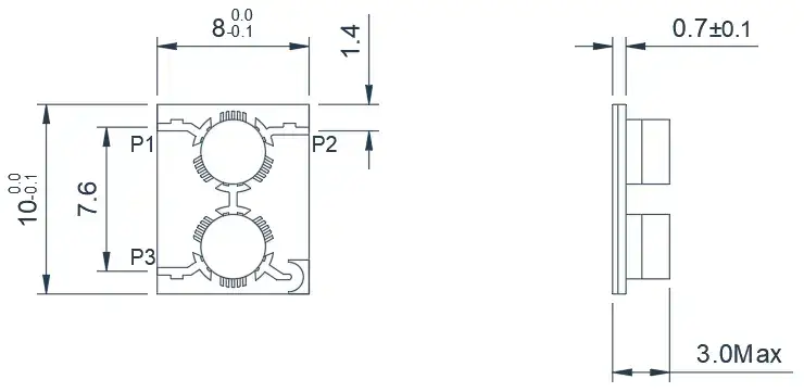
This is a standard X-band Microstrip Dual-Junction Circulator. It can be customized based on frequency bands, power, and size requirements.
| Model | Frequency(GHz) | BW Max | Insertion loss(dB) Max | Isolation(dB)Min | VSWR Max | operating temperature(℃ ) | PK/CW/RP(Watt) | Direction |
|---|---|---|---|---|---|---|---|---|
| HMDHA80T120G⬇ |
8.0~12.0 |
FULL |
0.6(P1-P2) 1.2(P2-P3) |
16.0(P2-P1) 28.0(P3-P2) |
1.35 | -55~+85 | 20/10/3 | Clockwise |
| HMDHB80T120G⬇ |
8.0~12.0 |
FULL |
0.6(P1-P2) 1.2(P2-P3) |
16.0(P2-P1) 28.0(P3-P2) |
1.35 | -55~+85 | 20/10/3 | Counter Clockwise |
| HMDHA85T105G⬇ |
8.5~10.5 |
FULL |
0.4(P1-P2) 0.8(P2-P3) |
20.0(P2-P1) 30.0(P3-P2) |
1.25 | -55~+85 | 20/10/3 | Clockwise |
| HMDHB85T105G⬇ |
8.5~10.5 |
FULL |
0.4(P1-P2) 0.8(P2-P3) |
20.0(P2-P1) 30.0(P3-P2) |
1.25 | -55~+85 | 20/10/3 | Counter Clockwise |
8.0~12.0GHz Typical Dual-Junction Microstrip Circulator
Product Overview
This is an X-band Microstrip Dual-Junction Circulator. As shown in the diagram, the antenna port has
been moved to the center position, making it more convenient for customer engineers to design their
circuits according to the usage scenario. It can be customized based on frequency bands, power, and size
requirements.
Model
Frequency(GHz)
BW Max
Insertion loss(dB) Max
Isolation(dB)Min
VSWR Max
operating temperature(℃ )
PK/CW/RP(Watt)
Direction
HMDYA80T120G⬇
8.0~12.0
FULL
0.65(P1-P2)
1.3(P2-P3)
16.0(P2-P1)
28.0(P3-P2)
1.35
-55~+85
20/10/3
Clockwise
HMDYB80T120G⬇
8.0~12.0
FULL
0.65(P1-P2)
1.3(P2-P3)
16.0(P2-P1)
28.0(P3-P2)
1.35
-55~+85
20/10/3
Counter Clockwise
HMDYA85T105G⬇
8.5~10.5
FULL
0.5(P1-P2)
0.9(P2-P3)
20.0(P2-P1)
30.0(P3-P2)
1.25
-55~+85
20/10/3
Clockwise
HMDYB85T105G⬇
8.5~10.5
FULL
0.5(P1-P2)
0.9(P2-P3)
20.0(P2-P1)
30.0(P3-P2)
1.25
-55~+85
20/10/3
Counter Clockwise
14.0~18.0GHz Typical Dual-Junction Microstrip Circulator
Product Overview
This is a standard Ku-band Microstrip Dual-Junction Circulator. It can be customized based on frequency
bands, power, and size requirements.
Model
Frequency(GHz)
BW Max
Insertion loss(dB) Max
Isolation(dB)Min
VSWR Max
operating temperature(℃ )
PK/CW/RP(Watt)
Direction
HMDHA140T180G⬇
14.0~18.0
FULL
0.5(P1-P2)
0.9(P2-P3)
17.0(P2-P1)
28.0(P3-P2)
1.3
-55~+85
20/10/3
Clockwise
HMDHB140T180G⬇
14.0~18.0
FULL
0.5(P1-P2)
0.9(P2-P3)
17.0(P2-P1)
28.0(P3-P2)
1.3
-55~+85
20/10/3
Counter Clockwise
14.0~18.0GHz Typical Dual-Junction Microstrip Circulator
Product Overview
This is an Ku-band Microstrip Dual-Junction Circulator. As shown in the diagram, the antenna port has
been moved to the center position, making it more convenient for customer engineers to design their
circuits according to the usage scenario. It can be customized based on frequency bands, power, and size
requirements.
Model
Frequency(GHz)
BW Max
Insertion loss(dB) Max
Isolation(dB)Min
VSWR Max
operating temperature(℃ )
PK/CW/RP(Watt)
Direction
HMDYA140T180G⬇
14.0~18.0
FULL
0.6(P1-P2)
1.1(P2-P3)
16.0(P2-P1)
28.0(P3-P2)
1.35
-55~+85
20/10/3
Clockwise
HMDYB140T180G⬇
14.0~18.0
FULL
0.6(P1-P2)
1.1(P2-P3)
16.0(P2-P1)
28.0(P3-P2)
1.35
-55~+85
20/10/3
Counter Clockwise
About HzBeat
HzBeat is a leading RF component manufacturer specializing in RF circulators and isolators, as a global supplier of RF circulators and isolators (20MHz–200GHz), we providing microstrip, drop-in, coaxial, and waveguide solutions for communication systems, radar, satellite, and medical imaging.
For detailed technical documentation, sample requests, or customization needs, please do not hesitate to contact us. — we respond within 24 hours to ensure you get precise solutions for your design.
Customization & Selection Guide
- Operating Band:Ensure it covers all frequencies required by your system.
- Power Handling Capacity:Select based on your system's transmit power (average and peak), allowing a certain margin.
- Performance Requirements:Define specific requirements for Insertion Loss, Isolation, and VSWR/Return Loss.
- Environmental Conditions:Consider operating temperature range, vibration, humidity, etc.
- Cost & Delivery:Balance cost and project timeline while meeting performance requirements.
Why Choose Our Product
- Profound Technical Expertise:We have over 18 years of R&D experience in ferrite materials and microwave magnetics.
- Fully Automated Production Lines:Ensure consistent excellence and reliability in every unit.
- Professional Application Support:Our engineering team provides timely technical selection, customization, and failure analysis services.
- Competitive Pricing & Lead Times:Economies of scale from mass production enable us to respond quickly to your orders.
Related Products
Questions? Feel Free to Reach Out Via Message.
Tell us frequency band, target IL/Isolation/VSWR, power level and timeline — we’ll match the best topology and deliver S-parameters.We will contact you within 24 hours.
Product Overview
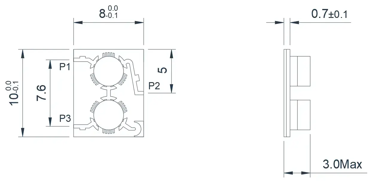
This is an X-band Microstrip Dual-Junction Circulator. As shown in the diagram, the antenna port has been moved to the center position, making it more convenient for customer engineers to design their circuits according to the usage scenario. It can be customized based on frequency bands, power, and size requirements.
| Model | Frequency(GHz) | BW Max | Insertion loss(dB) Max | Isolation(dB)Min | VSWR Max | operating temperature(℃ ) | PK/CW/RP(Watt) | Direction |
|---|---|---|---|---|---|---|---|---|
| HMDYA80T120G⬇ |
8.0~12.0 |
FULL |
0.65(P1-P2) 1.3(P2-P3) |
16.0(P2-P1) 28.0(P3-P2) |
1.35 | -55~+85 | 20/10/3 | Clockwise |
| HMDYB80T120G⬇ |
8.0~12.0 |
FULL |
0.65(P1-P2) 1.3(P2-P3) |
16.0(P2-P1) 28.0(P3-P2) |
1.35 | -55~+85 | 20/10/3 | Counter Clockwise |
| HMDYA85T105G⬇ |
8.5~10.5 |
FULL |
0.5(P1-P2) 0.9(P2-P3) |
20.0(P2-P1) 30.0(P3-P2) |
1.25 | -55~+85 | 20/10/3 | Clockwise |
| HMDYB85T105G⬇ |
8.5~10.5 |
FULL |
0.5(P1-P2) 0.9(P2-P3) |
20.0(P2-P1) 30.0(P3-P2) |
1.25 | -55~+85 | 20/10/3 | Counter Clockwise |
14.0~18.0GHz Typical Dual-Junction Microstrip Circulator
Product Overview
This is a standard Ku-band Microstrip Dual-Junction Circulator. It can be customized based on frequency
bands, power, and size requirements.
Model
Frequency(GHz)
BW Max
Insertion loss(dB) Max
Isolation(dB)Min
VSWR Max
operating temperature(℃ )
PK/CW/RP(Watt)
Direction
HMDHA140T180G⬇
14.0~18.0
FULL
0.5(P1-P2)
0.9(P2-P3)
17.0(P2-P1)
28.0(P3-P2)
1.3
-55~+85
20/10/3
Clockwise
HMDHB140T180G⬇
14.0~18.0
FULL
0.5(P1-P2)
0.9(P2-P3)
17.0(P2-P1)
28.0(P3-P2)
1.3
-55~+85
20/10/3
Counter Clockwise
14.0~18.0GHz Typical Dual-Junction Microstrip Circulator
Product Overview
This is an Ku-band Microstrip Dual-Junction Circulator. As shown in the diagram, the antenna port has
been moved to the center position, making it more convenient for customer engineers to design their
circuits according to the usage scenario. It can be customized based on frequency bands, power, and size
requirements.
Model
Frequency(GHz)
BW Max
Insertion loss(dB) Max
Isolation(dB)Min
VSWR Max
operating temperature(℃ )
PK/CW/RP(Watt)
Direction
HMDYA140T180G⬇
14.0~18.0
FULL
0.6(P1-P2)
1.1(P2-P3)
16.0(P2-P1)
28.0(P3-P2)
1.35
-55~+85
20/10/3
Clockwise
HMDYB140T180G⬇
14.0~18.0
FULL
0.6(P1-P2)
1.1(P2-P3)
16.0(P2-P1)
28.0(P3-P2)
1.35
-55~+85
20/10/3
Counter Clockwise
About HzBeat
HzBeat is a leading RF component manufacturer specializing in RF circulators and isolators, as a global supplier of RF circulators and isolators (20MHz–200GHz), we providing microstrip, drop-in, coaxial, and waveguide solutions for communication systems, radar, satellite, and medical imaging.
For detailed technical documentation, sample requests, or customization needs, please do not hesitate to contact us. — we respond within 24 hours to ensure you get precise solutions for your design.
Customization & Selection Guide
- Operating Band:Ensure it covers all frequencies required by your system.
- Power Handling Capacity:Select based on your system's transmit power (average and peak), allowing a certain margin.
- Performance Requirements:Define specific requirements for Insertion Loss, Isolation, and VSWR/Return Loss.
- Environmental Conditions:Consider operating temperature range, vibration, humidity, etc.
- Cost & Delivery:Balance cost and project timeline while meeting performance requirements.
Why Choose Our Product
- Profound Technical Expertise:We have over 18 years of R&D experience in ferrite materials and microwave magnetics.
- Fully Automated Production Lines:Ensure consistent excellence and reliability in every unit.
- Professional Application Support:Our engineering team provides timely technical selection, customization, and failure analysis services.
- Competitive Pricing & Lead Times:Economies of scale from mass production enable us to respond quickly to your orders.
Related Products
Questions? Feel Free to Reach Out Via Message.
Tell us frequency band, target IL/Isolation/VSWR, power level and timeline — we’ll match the best topology and deliver S-parameters.We will contact you within 24 hours.
Product Overview
This is a standard Ku-band Microstrip Dual-Junction Circulator. It can be customized based on frequency bands, power, and size requirements.
| Model | Frequency(GHz) | BW Max | Insertion loss(dB) Max | Isolation(dB)Min | VSWR Max | operating temperature(℃ ) | PK/CW/RP(Watt) | Direction |
|---|---|---|---|---|---|---|---|---|
| HMDHA140T180G⬇ |
14.0~18.0 |
FULL |
0.5(P1-P2) 0.9(P2-P3) |
17.0(P2-P1) 28.0(P3-P2) |
1.3 | -55~+85 | 20/10/3 | Clockwise |
| HMDHB140T180G⬇ |
14.0~18.0 |
FULL |
0.5(P1-P2) 0.9(P2-P3) |
17.0(P2-P1) 28.0(P3-P2) |
1.3 | -55~+85 | 20/10/3 | Counter Clockwise |
14.0~18.0GHz Typical Dual-Junction Microstrip Circulator
Product Overview
This is an Ku-band Microstrip Dual-Junction Circulator. As shown in the diagram, the antenna port has
been moved to the center position, making it more convenient for customer engineers to design their
circuits according to the usage scenario. It can be customized based on frequency bands, power, and size
requirements.
Model
Frequency(GHz)
BW Max
Insertion loss(dB) Max
Isolation(dB)Min
VSWR Max
operating temperature(℃ )
PK/CW/RP(Watt)
Direction
HMDYA140T180G⬇
14.0~18.0
FULL
0.6(P1-P2)
1.1(P2-P3)
16.0(P2-P1)
28.0(P3-P2)
1.35
-55~+85
20/10/3
Clockwise
HMDYB140T180G⬇
14.0~18.0
FULL
0.6(P1-P2)
1.1(P2-P3)
16.0(P2-P1)
28.0(P3-P2)
1.35
-55~+85
20/10/3
Counter Clockwise
About HzBeat
HzBeat is a leading RF component manufacturer specializing in RF circulators and isolators, as a global supplier of RF circulators and isolators (20MHz–200GHz), we providing microstrip, drop-in, coaxial, and waveguide solutions for communication systems, radar, satellite, and medical imaging.
For detailed technical documentation, sample requests, or customization needs, please do not hesitate to contact us. — we respond within 24 hours to ensure you get precise solutions for your design.
Customization & Selection Guide
- Operating Band:Ensure it covers all frequencies required by your system.
- Power Handling Capacity:Select based on your system's transmit power (average and peak), allowing a certain margin.
- Performance Requirements:Define specific requirements for Insertion Loss, Isolation, and VSWR/Return Loss.
- Environmental Conditions:Consider operating temperature range, vibration, humidity, etc.
- Cost & Delivery:Balance cost and project timeline while meeting performance requirements.
Why Choose Our Product
- Profound Technical Expertise:We have over 18 years of R&D experience in ferrite materials and microwave magnetics.
- Fully Automated Production Lines:Ensure consistent excellence and reliability in every unit.
- Professional Application Support:Our engineering team provides timely technical selection, customization, and failure analysis services.
- Competitive Pricing & Lead Times:Economies of scale from mass production enable us to respond quickly to your orders.
Related Products
Questions? Feel Free to Reach Out Via Message.
Tell us frequency band, target IL/Isolation/VSWR, power level and timeline — we’ll match the best topology and deliver S-parameters.We will contact you within 24 hours.
Product Overview
This is an Ku-band Microstrip Dual-Junction Circulator. As shown in the diagram, the antenna port has been moved to the center position, making it more convenient for customer engineers to design their circuits according to the usage scenario. It can be customized based on frequency bands, power, and size requirements.
| Model | Frequency(GHz) | BW Max | Insertion loss(dB) Max | Isolation(dB)Min | VSWR Max | operating temperature(℃ ) | PK/CW/RP(Watt) | Direction |
|---|---|---|---|---|---|---|---|---|
| HMDYA140T180G⬇ |
14.0~18.0 |
FULL |
0.6(P1-P2) 1.1(P2-P3) |
16.0(P2-P1) 28.0(P3-P2) |
1.35 | -55~+85 | 20/10/3 | Clockwise |
| HMDYB140T180G⬇ |
14.0~18.0 |
FULL |
0.6(P1-P2) 1.1(P2-P3) |
16.0(P2-P1) 28.0(P3-P2) |
1.35 | -55~+85 | 20/10/3 | Counter Clockwise |
About HzBeat
HzBeat is a leading RF component manufacturer specializing in RF circulators and isolators, as a global supplier of RF circulators and isolators (20MHz–200GHz), we providing microstrip, drop-in, coaxial, and waveguide solutions for communication systems, radar, satellite, and medical imaging.
For detailed technical documentation, sample requests, or customization needs, please do not hesitate to contact us. — we respond within 24 hours to ensure you get precise solutions for your design.
Customization & Selection Guide
- Operating Band:Ensure it covers all frequencies required by your system.
- Power Handling Capacity:Select based on your system's transmit power (average and peak), allowing a certain margin.
- Performance Requirements:Define specific requirements for Insertion Loss, Isolation, and VSWR/Return Loss.
- Environmental Conditions:Consider operating temperature range, vibration, humidity, etc.
- Cost & Delivery:Balance cost and project timeline while meeting performance requirements.
Why Choose Our Product
- Profound Technical Expertise:We have over 18 years of R&D experience in ferrite materials and microwave magnetics.
- Fully Automated Production Lines:Ensure consistent excellence and reliability in every unit.
- Professional Application Support:Our engineering team provides timely technical selection, customization, and failure analysis services.
- Competitive Pricing & Lead Times:Economies of scale from mass production enable us to respond quickly to your orders.